CN110901951A - A multifunctional tail rotor test system - Google Patents

A multifunctional tail rotor test system Download PDF

Info

Publication number
CN110901951A
CN110901951A CN201911119255.9A CN201911119255A CN110901951A CN 110901951 A CN110901951 A CN 110901951A CN 201911119255 A CN201911119255 A CN 201911119255A CN 110901951 A CN110901951 A CN 110901951A
Authority
CN
China
Prior art keywords
tail rotor
transmission shaft
conventional structure
test
ducted
Prior art date
Legal status (The legal status is an assumption and is not a legal conclusion. Google has not performed a legal analysis and makes no representation as to the accuracy of the status listed.)
Granted
Application number
CN201911119255.9A
Other languages
Chinese (zh)
Other versions
CN110901951B (en
Inventor
李黎明
莫胜男
王久龙
薛伟松
佟强
肖培军
于国庆
赵聪聪
蔡明程
孙天航
Current Assignee (The listed assignees may be inaccurate. Google has not performed a legal analysis and makes no representation or warranty as to the accuracy of the list.)
Harbin Aircraft Industry Group Co Ltd
Original Assignee
Harbin Aircraft Industry Group Co Ltd
Priority date (The priority date is an assumption and is not a legal conclusion. Google has not performed a legal analysis and makes no representation as to the accuracy of the date listed.)
Filing date
Publication date
Application filed by Harbin Aircraft Industry Group Co Ltd filed Critical Harbin Aircraft Industry Group Co Ltd
Priority to CN201911119255.9A priority Critical patent/CN110901951B/en
Publication of CN110901951A publication Critical patent/CN110901951A/en
Application granted granted Critical
Publication of CN110901951B publication Critical patent/CN110901951B/en
Active legal-status Critical Current
Anticipated expiration legal-status Critical

Links

Images

Classifications

    • BPERFORMING OPERATIONS; TRANSPORTING
    • B64AIRCRAFT; AVIATION; COSMONAUTICS
    • B64FGROUND OR AIRCRAFT-CARRIER-DECK INSTALLATIONS SPECIALLY ADAPTED FOR USE IN CONNECTION WITH AIRCRAFT; DESIGNING, MANUFACTURING, ASSEMBLING, CLEANING, MAINTAINING OR REPAIRING AIRCRAFT, NOT OTHERWISE PROVIDED FOR; HANDLING, TRANSPORTING, TESTING OR INSPECTING AIRCRAFT COMPONENTS, NOT OTHERWISE PROVIDED FOR
    • B64F5/00Designing, manufacturing, assembling, cleaning, maintaining or repairing aircraft, not otherwise provided for; Handling, transporting, testing or inspecting aircraft components, not otherwise provided for
    • B64F5/60Testing or inspecting aircraft components or systems

Landscapes

  • Engineering & Computer Science (AREA)
  • Manufacturing & Machinery (AREA)
  • Transportation (AREA)
  • Aviation & Aerospace Engineering (AREA)
  • Testing Of Devices, Machine Parts, Or Other Structures Thereof (AREA)
  • Force Measurement Appropriate To Specific Purposes (AREA)

Abstract

本发明涉及一种多功能直升机尾桨试验系统,包括:试验台体、三相异步电机、电机转速控制系统、桨距控制系统、变速箱、涵道尾桨传动轴、涵道尾桨、常规结构尾桨传动轴、常规结构尾桨、测力杆系、测力天平、第一扭矩传感器、第二扭矩传感器、声级计、风速风温测量仪和数据采集系统。本发明可满足常规结构尾桨和涵道尾桨等多种结构形式尾桨的试验要求,可进行性能试验、动力学试验、噪声研究、地面载荷测量等多种试验项目,完全模拟真机进行试验,边界条件与尾桨工况一致性高。

Figure 201911119255

The invention relates to a multifunctional helicopter tail rotor test system, comprising: a test bed body, a three-phase asynchronous motor, a motor speed control system, a pitch control system, a gearbox, a ducted tail rotor drive shaft, a ducted tail rotor, a conventional Structural tail rotor drive shaft, conventional structural tail rotor, force measuring rod system, force measuring balance, first torque sensor, second torque sensor, sound level meter, wind speed and temperature measuring instrument and data acquisition system. The invention can meet the test requirements of various structural types of tail rotors such as conventional structure tail rotor and ducted tail rotor, and can carry out various test items such as performance test, dynamic test, noise research, ground load measurement, etc., completely simulating the real machine. In the test, the boundary conditions are highly consistent with the tail rotor operating conditions.

Figure 201911119255

Description

Multifunctional tail rotor test system
Technical Field
The invention relates to the field of helicopter tests, in particular to a multifunctional tail rotor test system.
Background
The tail rotor is an important component of a helicopter lift system, is mainly used for balancing reactive torque during flight and is also a main component of an operation course. The tail rotor is divided into a seesaw type, a universal joint type, a hinge type, a bearingless type, a scissor type, a duct tail rotor and the like from the structural form, and compared with the duct tail rotor, the former five tail rotor forms can be collectively called as the tail rotor with the conventional structure. In the model development process, in order to determine the performance and efficiency of the tail rotor, a series of tests such as performance test, dynamics test, noise research, ground load measurement and the like need to be carried out on the tail rotor, and whether the design of the tail rotor meets the requirements or not is verified according to the test results.
At present, the existing similar test device in China is generally designed specifically only for the tail rotor with one structural form, the function of the test device is single, and only one or a few of the test items can be carried out.
Disclosure of Invention
The purpose of the invention is: the multifunctional tail rotor test system aims to solve the limitation of single function of the existing test device, can meet the test requirements of tail rotors with various structural forms such as conventional tail rotors and ducted tail rotors, and can perform various test items such as performance tests, dynamic tests, noise researches, ground load measurement and the like.
The technical scheme of the invention is as follows:
a multifunctional helicopter tail rotor test system is provided, comprising: the test bed comprises a test bed body 1, a three-phase asynchronous motor 2, a motor rotating speed control system 3, a propeller pitch control system 4, a gearbox 5, a duct tail rotor transmission shaft 6, a duct tail rotor 7, a conventional structure tail rotor transmission shaft 8, a conventional structure tail rotor 9, a force measuring rod system 10, a force measuring balance 11, a first torque sensor 12a, a second torque sensor 12b, a sound level meter 13, a wind speed and wind temperature measuring instrument 14 and a data acquisition system 15; the first torque sensor 12a and the second torque sensor 12b each have a function of measuring a rotational speed;
the three-phase asynchronous motor, the duct tail rotor 7 and the tail rotor 9 with the conventional structure are all fixed on the test bed body 1, and the duct tail rotor transmission shaft 6 and the tail rotor transmission shaft 8 with the conventional structure are both rotatably arranged on the test bed body 1; the output end of the three-phase asynchronous motor is connected with a gearbox, one end of the ducted tail rotor transmission shaft and one end of the tail rotor transmission shaft with the conventional structure are both connected with the gearbox, and the gearbox transmits torque to the ducted tail rotor transmission shaft and the tail rotor transmission shaft with the conventional structure; the other end of the culvert tail rotor transmission shaft is in power connection with the culvert tail rotor and transmits the torque to the culvert tail rotor, and the other end of the tail rotor transmission shaft in the conventional structure is in power connection with the tail rotor in the conventional structure and transmits the torque to the tail rotor in the conventional structure;
the force measuring rod system 10 is used for measuring the tension of the tail rotor;
the force measuring balance 11 is used for measuring the pulling force of the tail rotor with a conventional structure;
the first torque sensor 12a is used for measuring the torque and the rotating speed of the ducted tail rotor transmission shaft;
the second torque sensor 12b is used for measuring the torque and the rotating speed of the tail rotor transmission shaft with the conventional structure;
the ducted tail rotor transmission and the tail rotor of the conventional structure are both provided with a sound level meter 13 and a wind speed and wind temperature measuring instrument 14, and the measured noise level and the measured wind speed and wind temperature of the tail rotor are fed back to a data acquisition system 15;
the motor rotating speed control system 3 is used for controlling the rotating speed of the motor; the pitch control system 4 is used for controlling the pitch of the ducted tail rotor and the tail rotor with a conventional structure.
Further, the test bed body 1 is of a truss structure. Preferably, the truss structure is constructed of steel and concrete.
Further, the gearbox is a speed increasing box.
Furthermore, the duct tail rotor transmission shaft is arranged horizontally, and the tail rotor transmission shaft with the conventional structure is arranged vertically.
Further, the power of the three asynchronous machines 2 is 400 kW.
Further, a first torque sensor 12a is connected in series with the ducted tail rotor drive shaft.
Further, a second torque sensor 12b is connected in series with the conventional configuration of the tailrotor drive shaft.
Further, the force measuring bar system 10 adopts 6 series force sensors.
The invention can drag and control the rotation of the tail rotor, simulate the working state of the tail rotor of the helicopter in the flying process, and measure the parameters of the tail rotor such as the tension, the power, the noise level and the like. The invention can be used for performance tests, dynamic tests, noise researches, ground load measurement and other ground tests of duct tail rotors and tail rotors with conventional structures. The invention can carry out duct tail rotor test and conventional structure tail rotor test, uses real duct structure, front edge cone, upper vertical tail and fairing as test pieces, the tail rotor is installed according to the installation posture, completely simulates a real machine, and the test boundary condition is real.
The invention has the advantages that: the invention can meet the test requirements of tail rotors with various structural forms such as tail rotors with conventional structures, duct tail rotors and the like, can carry out various test items such as performance tests, dynamic tests, noise researches, ground load measurement and the like, completely simulates a real machine to carry out tests, and has high consistency of boundary conditions and tail rotor working conditions.
Drawings
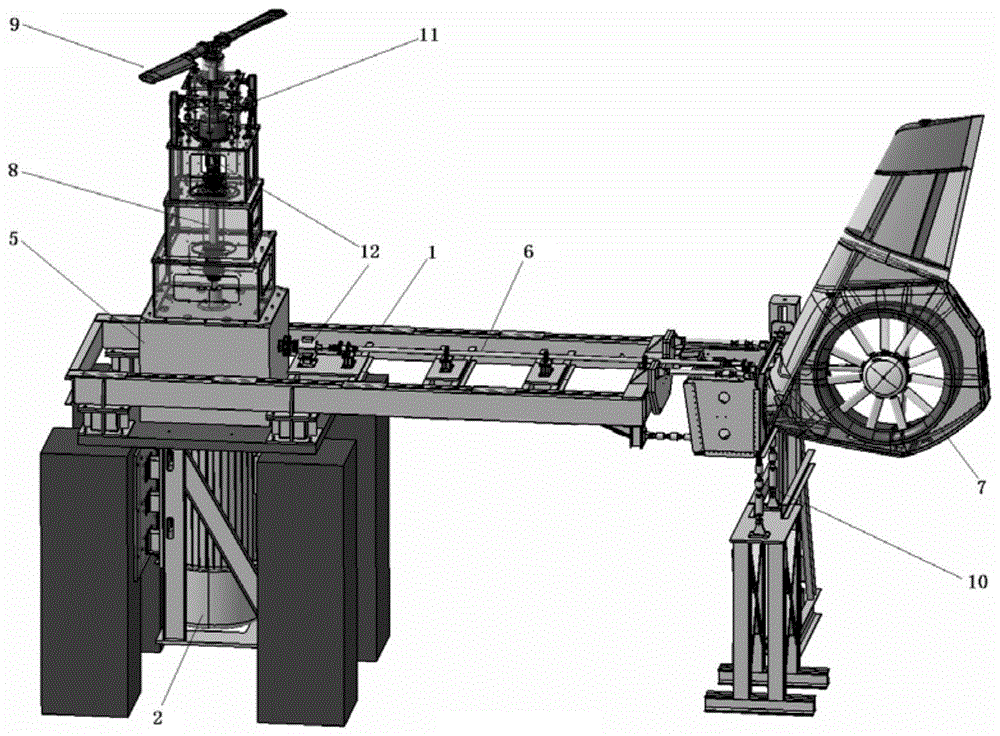
FIG. 1 is a schematic diagram of the system architecture of the present invention;
FIG. 2 is a functional block diagram of the testing system of the present invention;
wherein: the test bed comprises a test bed body 1, three asynchronous motors 2, a gearbox 5, a duct-6 tail rotor transmission shaft 7, a duct-7 tail rotor, a conventional tail rotor transmission shaft 8, a conventional tail rotor with a conventional structure 9, a force measuring bar system 10, a force measuring balance 11, a first torque sensor 12a and a second torque sensor 12 b.
Detailed Description
The present invention is described in further detail below.
Embodiment 1 provides a multi-functional helicopter tail-rotor test system, includes: the test bed comprises a test bed body 1, a three-phase asynchronous motor 2, a motor rotating speed control system 3, a propeller pitch control system 4, a gearbox 5, a duct tail rotor transmission shaft 6, a duct tail rotor 7, a conventional structure tail rotor transmission shaft 8, a conventional structure tail rotor 9, a force measuring rod system 10, a force measuring balance 11, a first torque sensor 12a, a second torque sensor 12b, a sound level meter 13, a wind speed and wind temperature measuring instrument 14 and a data acquisition system 15; the first torque sensor 12a and the second torque sensor 12b each have a function of measuring a rotational speed;
the three-phase asynchronous motor, the duct tail rotor 7 and the tail rotor 9 with the conventional structure are all fixed on the test bed body 1, and the duct tail rotor transmission shaft 6 and the tail rotor transmission shaft 8 with the conventional structure are both rotatably arranged on the test bed body 1; the output end of the three-phase asynchronous motor is connected with a gearbox, one end of the ducted tail rotor transmission shaft and one end of the tail rotor transmission shaft with the conventional structure are both connected with the gearbox, and the gearbox transmits torque to the ducted tail rotor transmission shaft and the tail rotor transmission shaft with the conventional structure; the other end of the culvert tail rotor transmission shaft is in power connection with the culvert tail rotor and transmits the torque to the culvert tail rotor, and the other end of the tail rotor transmission shaft in the conventional structure is in power connection with the tail rotor in the conventional structure and transmits the torque to the tail rotor in the conventional structure;
the force measuring rod system 10 is used for measuring the tension of the tail rotor;
the force measuring balance 11 is used for measuring the pulling force of the tail rotor with a conventional structure;
the first torque sensor 12a is used for measuring the torque and the rotating speed of the ducted tail rotor transmission shaft;
the second torque sensor 12b is used for measuring the torque and the rotating speed of the tail rotor transmission shaft with the conventional structure;
the ducted tail rotor transmission and the tail rotor of the conventional structure are both provided with a sound level meter 13 and a wind speed and wind temperature measuring instrument 14, and the measured noise level and the measured wind speed and wind temperature of the tail rotor are fed back to a data acquisition system 15;
the motor rotating speed control system 3 is used for controlling the rotating speed of the motor; the pitch control system 4 is used for controlling the pitch of the ducted tail rotor and the tail rotor with a conventional structure.
The test bed body 1 is of a truss structure. The gearbox is a speed increasing box.
The duct tail rotor transmission shaft is arranged horizontally, and the tail rotor transmission shaft with a conventional structure is arranged vertically.
Embodiment 2 provides a multi-functional helicopter tail-rotor test system, includes: the test bed comprises a test bed body 1, a three-phase asynchronous motor 2, a motor rotating speed control system 3, a propeller pitch control system 4, a gearbox 5, a duct tail rotor transmission shaft 6, a duct tail rotor 7, a conventional structure tail rotor transmission shaft 8, a conventional structure tail rotor 9, a force measuring rod system 10, a force measuring balance 11, a first torque sensor 12a, a second torque sensor 12b, a sound level meter 13, a wind speed and wind temperature measuring instrument 14 and a data acquisition system 15; the first torque sensor 12a and the second torque sensor 12b each have a function of measuring a rotational speed;
the three-phase asynchronous motor, the duct tail rotor 7 and the tail rotor 9 with the conventional structure are all fixed on the test bed body 1, and the duct tail rotor transmission shaft 6 and the tail rotor transmission shaft 8 with the conventional structure are both rotatably arranged on the test bed body 1; the output end of the three-phase asynchronous motor is connected with a gearbox, one end of the ducted tail rotor transmission shaft and one end of the tail rotor transmission shaft with the conventional structure are both connected with the gearbox, and the gearbox transmits torque to the ducted tail rotor transmission shaft and the tail rotor transmission shaft with the conventional structure; the other end of the culvert tail rotor transmission shaft is in power connection with the culvert tail rotor and transmits the torque to the culvert tail rotor, and the other end of the tail rotor transmission shaft in the conventional structure is in power connection with the tail rotor in the conventional structure and transmits the torque to the tail rotor in the conventional structure;
the force measuring rod system 10 is used for measuring the tension of the tail rotor;
the force measuring balance 11 is used for measuring the pulling force of the tail rotor with a conventional structure;
the first torque sensor 12a is used for measuring the torque and the rotating speed of the ducted tail rotor transmission shaft;
the second torque sensor 12b is used for measuring the torque and the rotating speed of the tail rotor transmission shaft with the conventional structure;
the ducted tail rotor transmission and the tail rotor of the conventional structure are both provided with a sound level meter 13 and a wind speed and wind temperature measuring instrument 14, and the measured noise level and the measured wind speed and wind temperature of the tail rotor are fed back to a data acquisition system 15;
the motor rotating speed control system 3 is used for controlling the rotating speed of the motor; the pitch control system 4 is used for controlling the pitch of the ducted tail rotor and the tail rotor with a conventional structure.
The test bed body 1 is of a truss structure. The truss structure is composed of steel bars and concrete.
The gearbox is a speed increasing box.
The duct tail rotor transmission shaft is arranged horizontally, and the tail rotor transmission shaft with a conventional structure is arranged vertically. The power of the three asynchronous machines 2 is 400 kW.
A first torque sensor 12a is connected in series with the ducted tail rotor drive shaft.
A second torque sensor 12b is connected in series with the conventional configuration of the tail rotor drive shaft.
The load cell line 10 employs 6 series force sensors.

Claims (9)

1. A multi-function helicopter tail rotor test system comprising: the test bed comprises a test bed body, a three-phase asynchronous motor, a motor rotating speed control system, a propeller pitch control system, a gearbox, a ducted tail rotor transmission shaft, a ducted tail rotor, a conventional structure tail rotor transmission shaft, a conventional structure tail rotor, a force measuring rod system 10, a force measuring balance, a first torque sensor, a second torque sensor, a sound level meter, a wind speed and wind temperature measuring instrument 14 and a data acquisition system; the first torque sensor and the second torque sensor have the function of measuring the rotating speed;
the three-phase asynchronous motor, the duct tail rotor and the tail rotor with the conventional structure are all fixed on the test bed body, and the duct tail rotor transmission shaft and the tail rotor transmission shaft with the conventional structure are all rotatably arranged on the test bed body; the output end of the three-phase asynchronous motor is connected with a gearbox, one end of the ducted tail rotor transmission shaft and one end of the tail rotor transmission shaft with the conventional structure are both connected with the gearbox, and the gearbox transmits torque to the ducted tail rotor transmission shaft and the tail rotor transmission shaft with the conventional structure; the other end of the culvert tail rotor transmission shaft is in power connection with the culvert tail rotor and transmits the torque to the culvert tail rotor, and the other end of the tail rotor transmission shaft in the conventional structure is in power connection with the tail rotor in the conventional structure and transmits the torque to the tail rotor in the conventional structure;
the force measuring rod system is used for measuring the tension of the tail rotor;
the force measuring balance is used for measuring the pulling force of the tail rotor with a conventional structure;
the first torque sensor is used for measuring the torque and the rotating speed of the ducted tail rotor transmission shaft;
the second torque sensor is used for measuring the torque and the rotating speed of the tail rotor transmission shaft with the conventional structure;
the ducted tail rotor transmission and the tail rotor with the conventional structure are both provided with a sound level meter and a wind speed and wind temperature measuring instrument, and the measured noise level and the wind speed and wind temperature of the tail rotor are fed back to the data acquisition system;
the motor rotating speed control system is used for controlling the rotating speed of the motor; the propeller pitch control system is used for controlling the propeller pitch of the ducted tail rotor and the tail rotor with the conventional structure.
2. The multifunctional helicopter tail rotor test system of claim 1, further comprising: the force measuring rod adopts 6 series force sensors.
3. The multifunctional helicopter tail rotor test system of claim 1, further comprising: and the second torque sensor is connected with the tail rotor transmission shaft in series in a conventional structure.
4. The multifunctional helicopter tail rotor test system of claim 1, further comprising: the first torque sensor is connected in series with the ducted tail rotor transmission shaft.
5. The multifunctional helicopter tail rotor test system of claim 1, further comprising: the power of the three asynchronous motors is 400 kW.
6. The multifunctional helicopter tail rotor test system of claim 1, further comprising: the duct tail rotor transmission shaft is arranged horizontally, and the tail rotor transmission shaft with a conventional structure is arranged vertically.
7. The multifunctional helicopter tail rotor test system of claim 1, further comprising: the test bed body is of a truss structure.
8. The multifunctional helicopter tail rotor test system of claim 1, further comprising: the gearbox is a speed increasing box.
9. The multifunctional helicopter tail rotor testing system of claim 7, further comprising: the truss structure is composed of steel bars and concrete.
CN201911119255.9A 2019-11-15 2019-11-15 Multifunctional tail rotor test system Active CN110901951B (en)

Priority Applications (1)

Application Number Priority Date Filing Date Title
CN201911119255.9A CN110901951B (en) 2019-11-15 2019-11-15 Multifunctional tail rotor test system

Applications Claiming Priority (1)

Application Number Priority Date Filing Date Title
CN201911119255.9A CN110901951B (en) 2019-11-15 2019-11-15 Multifunctional tail rotor test system

Publications (2)

Publication Number Publication Date
CN110901951A true CN110901951A (en) 2020-03-24
CN110901951B CN110901951B (en) 2023-01-13

Family

ID=69817601

Family Applications (1)

Application Number Title Priority Date Filing Date
CN201911119255.9A Active CN110901951B (en) 2019-11-15 2019-11-15 Multifunctional tail rotor test system

Country Status (1)

Country Link
CN (1) CN110901951B (en)

Cited By (4)

* Cited by examiner, † Cited by third party
Publication number Priority date Publication date Assignee Title
CN111855201A (en) * 2020-09-01 2020-10-30 常州华创航空科技有限公司 Helicopter main reducer test bench
CN111994301A (en) * 2020-08-18 2020-11-27 常州华创航空科技有限公司 Helicopter transmission system test device and system
CN112407324A (en) * 2020-11-03 2021-02-26 中国直升机设计研究所 Helicopter tail rotor load measuring and mounting device
CN114919772A (en) * 2022-06-02 2022-08-19 燕山大学 Rotating mechanical fault simulation experiment table for single-rotor unmanned helicopter with tail rotor

Citations (21)

* Cited by examiner, † Cited by third party
Publication number Priority date Publication date Assignee Title
US4159642A (en) * 1978-03-02 1979-07-03 Avco Corporation Aircraft transmission test set
US4708305A (en) * 1987-01-30 1987-11-24 The United States Of America As Represented By The Administrator Of The National Aeronautics And Space Administration Helicopter anti-torque system using fuselage strakes
RU2028591C1 (en) * 1990-07-02 1995-02-09 Московский вертолетный завод им.М.Л.Миля Stand for member dynamic tests
US5693896A (en) * 1995-03-16 1997-12-02 Eurocopter France Test rig for rotors of gyrocraft
KR20030092603A (en) * 2002-05-30 2003-12-06 주식회사 동서종합기계 a tester for helicopter's trans mission
KR20040051729A (en) * 2002-12-11 2004-06-19 한국항공우주연구원 Helicopter tail-fan performance test bench
KR20090039563A (en) * 2007-10-18 2009-04-22 한국항공우주연구원 Helicopter Tail Rotor Test Device
US20120046141A1 (en) * 2010-08-20 2012-02-23 Redviking Group, Llc Transmission test system
CN102774509A (en) * 2012-06-28 2012-11-14 南京航空航天大学 Performance test bench for reaction torque device of helicopter
US20130184959A1 (en) * 2012-01-12 2013-07-18 Bell Helicopter Textron Inc. System and method of measuring and monitoring torque in a rotorcraft drive system
CN103913291A (en) * 2014-04-04 2014-07-09 郭春雨 Pod propelling system testing device
CN105067263A (en) * 2015-08-18 2015-11-18 鹰领航空高端装备技术秦皇岛有限公司 Endurance tester for combined joint bearing matching with tail rotor of tail rotor type helicopter
CN105547676A (en) * 2015-12-25 2016-05-04 北京航空航天大学 Multifunctional swing-arm type rotor wing test stand
CN105644780A (en) * 2014-11-28 2016-06-08 空客直升机 Tail rotor, method of balancing the tail rotor and rotorcraft
CN106017914A (en) * 2016-05-11 2016-10-12 湖南科技大学 Research and testing platform for vibration noises of helicopter transmission system
CN106525404A (en) * 2016-11-30 2017-03-22 中国直升机设计研究所 Tail rotor stand
CN106706275A (en) * 2015-07-29 2017-05-24 哈尔滨飞机工业集团有限责任公司 Test method for determining service life of helicopter composite material ducted vertical tail
CN206208506U (en) * 2016-10-09 2017-05-31 黄超 Propeller testboard bay
CN107328572A (en) * 2017-07-03 2017-11-07 贵州凯星液力传动机械有限公司 A kind of multifunctional high-power automatic transmission overall test device
CN108593243A (en) * 2018-04-23 2018-09-28 中国空气动力研究与发展中心低速空气动力研究所 A kind of helicopter built-up pattern experimental rig
CN110261057A (en) * 2019-07-03 2019-09-20 中国空气动力研究与发展中心低速空气动力研究所 A kind of lifting airscrew, fuselage and tail-rotor built-up pattern wind tunnel test system

Patent Citations (21)

* Cited by examiner, † Cited by third party
Publication number Priority date Publication date Assignee Title
US4159642A (en) * 1978-03-02 1979-07-03 Avco Corporation Aircraft transmission test set
US4708305A (en) * 1987-01-30 1987-11-24 The United States Of America As Represented By The Administrator Of The National Aeronautics And Space Administration Helicopter anti-torque system using fuselage strakes
RU2028591C1 (en) * 1990-07-02 1995-02-09 Московский вертолетный завод им.М.Л.Миля Stand for member dynamic tests
US5693896A (en) * 1995-03-16 1997-12-02 Eurocopter France Test rig for rotors of gyrocraft
KR20030092603A (en) * 2002-05-30 2003-12-06 주식회사 동서종합기계 a tester for helicopter's trans mission
KR20040051729A (en) * 2002-12-11 2004-06-19 한국항공우주연구원 Helicopter tail-fan performance test bench
KR20090039563A (en) * 2007-10-18 2009-04-22 한국항공우주연구원 Helicopter Tail Rotor Test Device
US20120046141A1 (en) * 2010-08-20 2012-02-23 Redviking Group, Llc Transmission test system
US20130184959A1 (en) * 2012-01-12 2013-07-18 Bell Helicopter Textron Inc. System and method of measuring and monitoring torque in a rotorcraft drive system
CN102774509A (en) * 2012-06-28 2012-11-14 南京航空航天大学 Performance test bench for reaction torque device of helicopter
CN103913291A (en) * 2014-04-04 2014-07-09 郭春雨 Pod propelling system testing device
CN105644780A (en) * 2014-11-28 2016-06-08 空客直升机 Tail rotor, method of balancing the tail rotor and rotorcraft
CN106706275A (en) * 2015-07-29 2017-05-24 哈尔滨飞机工业集团有限责任公司 Test method for determining service life of helicopter composite material ducted vertical tail
CN105067263A (en) * 2015-08-18 2015-11-18 鹰领航空高端装备技术秦皇岛有限公司 Endurance tester for combined joint bearing matching with tail rotor of tail rotor type helicopter
CN105547676A (en) * 2015-12-25 2016-05-04 北京航空航天大学 Multifunctional swing-arm type rotor wing test stand
CN106017914A (en) * 2016-05-11 2016-10-12 湖南科技大学 Research and testing platform for vibration noises of helicopter transmission system
CN206208506U (en) * 2016-10-09 2017-05-31 黄超 Propeller testboard bay
CN106525404A (en) * 2016-11-30 2017-03-22 中国直升机设计研究所 Tail rotor stand
CN107328572A (en) * 2017-07-03 2017-11-07 贵州凯星液力传动机械有限公司 A kind of multifunctional high-power automatic transmission overall test device
CN108593243A (en) * 2018-04-23 2018-09-28 中国空气动力研究与发展中心低速空气动力研究所 A kind of helicopter built-up pattern experimental rig
CN110261057A (en) * 2019-07-03 2019-09-20 中国空气动力研究与发展中心低速空气动力研究所 A kind of lifting airscrew, fuselage and tail-rotor built-up pattern wind tunnel test system

Non-Patent Citations (3)

* Cited by examiner, † Cited by third party
Title
吴志刚,秦强: "直升机旋翼试验台测试系统防干扰设计", 《探索 创新 交流——第五届中国航空学会青年科技论坛文集(第5集)》 *
梅火林: "多型号例行疲劳试验平台的研究与应用", 《2013年中国航空学会管理科学分会学术会议论文集》 *
陈德军: "直升机旋转试验台综合测试系统的设计", 《世界电子元器件》 *

Cited By (8)

* Cited by examiner, † Cited by third party
Publication number Priority date Publication date Assignee Title
CN111994301A (en) * 2020-08-18 2020-11-27 常州华创航空科技有限公司 Helicopter transmission system test device and system
CN111994301B (en) * 2020-08-18 2022-03-22 常州华创航空科技有限公司 Helicopter transmission system test device and system
CN111855201A (en) * 2020-09-01 2020-10-30 常州华创航空科技有限公司 Helicopter main reducer test bench
CN111855201B (en) * 2020-09-01 2022-03-22 常州华创航空科技有限公司 Helicopter main reducer test bench
CN112407324A (en) * 2020-11-03 2021-02-26 中国直升机设计研究所 Helicopter tail rotor load measuring and mounting device
CN112407324B (en) * 2020-11-03 2022-03-29 中国直升机设计研究所 Helicopter tail rotor load measuring and mounting device
CN114919772A (en) * 2022-06-02 2022-08-19 燕山大学 Rotating mechanical fault simulation experiment table for single-rotor unmanned helicopter with tail rotor
CN114919772B (en) * 2022-06-02 2024-08-13 燕山大学 Single rotor wing type unmanned helicopter rotating machinery fault simulation experiment table with tail rotor

Also Published As

Publication number Publication date
CN110901951B (en) 2023-01-13

Similar Documents

Publication Publication Date Title
CN110901951B (en) Multifunctional tail rotor test system
CN105547676B (en) A kind of arm-type rotor model.test system of multifunctional rotary
KR100913667B1 (en) Helicopter Tail Rotor Test Device
CN102562468B (en) For monitoring the system and method for the state of the rotor blade of wind turbine
CN103604608B (en) Propeller tensile test bench for light sport aircraft
CN205642791U (en) Wind -tunnel is with toper motion simulation device of rotatory guided missile
CN106441902B (en) A kind of sub- scale simulation aero-engine rotation test device and test method
CN109556878B (en) Synchronous measurement device and method for pneumatic performance and efficiency of electric propeller system
CN101464213A (en) Fan yawing test mechanism and fan set testing bench
CN111707442A (en) Numerical Model Measurement and Verification System of Propeller in Supersonic Wind Tunnel and Its Control Method
CN111693864B (en) Propeller characteristic simulation experiment device based on permanent magnet synchronous motor
CN111859649A (en) A method for establishing ground test conditions for wind turbine transmission chain based on virtual simulation
CN107719696A (en) A kind of dynamic characteristics synchronous testing device of axially compact type aircraft propeller
CN204740114U (en) A doubly-fed wind turbine shafting vibration testing device
CN102680895A (en) Wind power generation simulation platform and simulation method thereof
CN114544166B (en) Electromechanical coupling simulation experiment table for simulating wind power variable speed load and non-torsion load
CN107762709B (en) A horizontal axis tidal current energy turbine hydrodynamic performance test platform and test method
CN109297672A (en) A Pitch-Yaw Forced Vibration Dynamic Derivative Test Device Applicable to Mach 8.0
CN109795716A (en) A universal small steering gear sweep frequency test equipment and method
CN108438250A (en) Serial mixed power aircraft power system testboard bay
CN110779678A (en) Test bed capable of synchronously measuring aerodynamic characteristics and acoustic characteristics of large-size propeller
CN112798220B (en) Wind tunnel test device for tail boom type helicopter rotor wing model
CN116358757A (en) A test device for mechanical parameters of electric propulsion system of electric propulsion aircraft
CN104502093A (en) Fault simulation experiment device for helicopter tail transmission system
CN104091501B (en) Energy based on permanent-magnetic wind driven generator conversion dynamic model experiment platform and test method

Legal Events

Date Code Title Description
PB01 Publication
PB01 Publication
SE01 Entry into force of request for substantive examination
GR01 Patent grant
GR01 Patent grant