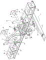
Electro-hydraulic control trowelling device and concrete slide die paver
Technical Field
The invention relates to the technical field of concrete sliding formwork pavers, in particular to an electro-hydraulic control trowelling device and a concrete sliding formwork paver.
Background
The concrete slip form paver is in the construction process, the formed concrete road surface is difficult to avoid flaws such as rough surface, longitudinal unevenness, air bubble floating slurry and the like, the existing treatment method is to manually treat by using a trowel, but a person cannot stand on the newly paved concrete road surface, the position in the middle of the road surface cannot be reached by hands, one method is to use an elongated trowel, the length is determined according to the width of the paved road surface, the other method is to frame a bridge crossing the concrete road surface, and the person stands on the bridge and bends over. The two manual treatments have low efficiency and influence the construction progress.
Disclosure of Invention
One of the purposes of the invention is to provide an electro-hydraulic control trowelling device installed on a concrete slip form paver, and the trowelling device can automatically trowelling the concrete surface, thereby saving the labor cost and improving the construction efficiency.
The technical scheme for realizing the purpose is as follows: the utility model provides a floating device of electric liquid control for concrete slide die paver which characterized in that: the concrete pavement trowelling device comprises a truss, a track, a traveling trolley and a traveling driving mechanism, wherein the truss is transversely arranged, the track is arranged on the truss along the length direction, the traveling trolley travels along the track, the traveling driving mechanism is used for driving the traveling trolley to travel along the track, an upper hinged frame is vertically arranged on the traveling trolley, the upper end of the upper hinged frame is rotatably arranged on the traveling trolley, the lower end of the upper hinged frame is hinged with a trowelling mechanism, and the traveling trolley is provided with a trowelling driving mechanism which is used for driving the upper hinged frame to drive the trowelling mechanism to trowelling.
The invention has the beneficial effects that:
the concrete sliding formwork paver is arranged on a concrete sliding formwork paver to work, and the concrete road surface can be automatically leveled at the same time by matching the concrete sliding formwork paver with a walking driving mechanism for driving the walking trolley to walk, so that the labor cost is saved, and the construction efficiency is improved.
Further, the trowelling mechanism comprises a trowelling plate, a middle hinged frame and two lower hinged frames, the trowelling plate is longitudinally arranged below the truss, one end of one of the lower hinged frames is hinged to one end of the back face of the trowelling plate, one end of the other lower hinged frame is hinged to the other end of the back face of the trowelling plate, the two lower hinged frames are symmetrically arranged, the middle hinged frame is hinged between the two lower hinged frames, and the lower end of the upper hinged frame is hinged to the middle of the middle hinged frame.
Furthermore, the floating driving mechanism comprises an auxiliary driving motor which is transversely arranged and is arranged on the walking trolley, the output end of the auxiliary driving motor is connected with a turntable, a connecting rod is connected between the turntable and the upper hinge frame, one end of the connecting rod is rotatably connected onto the turntable, the other end of the connecting rod is hinged to the middle of the upper hinge frame, and the end, connected with the turntable, of the connecting rod is eccentrically arranged relative to the rotating center of the turntable.
The auxiliary driving motor drives the upper hinge bracket to swing back and forth through the connecting rod, and then drives the trowelling plate to move back and forth through the middle hinge bracket and the two lower hinge brackets.
Furthermore, for avoiding the damage and the knot of the hydraulic oil conveying rubber pipes in the travelling process of the travelling trolley, the middle part of the truss is provided with a winder support, a winder is rotatably arranged on the winder support, and two hydraulic oil conveying rubber pipes connected with the auxiliary driving motor are wound on the winder.
Furthermore, in order to avoid the connecting end from being loosened due to tension generated on the connecting end of the hydraulic oil conveying rubber pipe in the walking process of the walking trolley, a rubber pipe balance wheel is further installed on the walking trolley, the rubber pipe balance wheel is a cylinder, two hydraulic connectors are arranged in the rubber pipe balance wheel, two ends of each hydraulic connector are exposed out of the rubber pipe balance wheel, and the two hydraulic oil conveying rubber pipes are respectively connected with the auxiliary driving motor through one hydraulic connector.
Furthermore, the walking driving mechanism comprises a driving seat frame arranged in the middle of the truss and a cable driving wheel rotatably arranged on the driving seat frame, a main driving motor for driving the cable driving wheel to rotate is further arranged on the driving seat frame, a driving cable is wound on the cable driving wheel, guide wheels are further respectively arranged at two ends of the truss, and two ends of the driving cable are respectively connected with the walking trolley after bypassing the guide wheels at the corresponding ends.
According to the invention, the cable driving wheel is driven to rotate forwards or reversely to drive the two ends of the driving cable to be automatically wound and unwound, so that the walking trolley is controlled to move left and right along the track.
Furthermore, a vertical upward connecting plate is arranged on the walking trolley, two transversely-arranged cable fixing rods penetrate through the connecting plate, nuts are respectively connected to the cable fixing rods on the two sides of the connecting plate in parallel, one end of each cable fixing rod is connected with a rope ring, and the rope rings are located at the opposite ends of the two cable fixing rods.
According to the invention, the axial position of the cable fixing rod can be adjusted through the nuts on the two sides of the connecting plate, so that the tension of the driving cable is adjusted.
Furthermore, the both sides of truss are connected with fixed connection frame, fixed connection frame includes the lead screw lift, and the lower extreme liftable of lead screw lift is connected with the lift seat, lift seat and truss fixed connection, have the fixed mounting board that is used for being connected with the slipform paver through the leg joint on the casing of lead screw lift.
The floating device is arranged on the slip form paver through a screw rod lifter with adjustable height so as to adapt to pavements with different heights.
Further, still install the lateral shifting electric hydraulic control system on the truss, the lateral shifting electric hydraulic control system includes the controller, automatically controlled switching-over valve, the governing valve, two travel switches are installed respectively at orbital both ends, be used for controlling the stroke of walking dolly, two travel switches connect the input at the controller, the control end of automatically controlled switching-over valve is connected at the output of controller, main drive motor connects between the work hydraulic fluid port A, B of automatically controlled switching-over valve, the hydraulic oil feeding system of concrete sliding mould paver is connected to pressure hydraulic fluid port P and the oil return port T of automatically controlled switching-over valve, the governing valve is connected in series at the pressure hydraulic fluid port P and the oil feeding system of automatically controlled switching-over valve and is connected.
The working principle of the transverse movement electro-hydraulic control system is as follows: the main driving motor drives the walking trolley to walk along the track, and after the travel switch at one end is triggered, the travel switch controls the electronic control reversing valve to reverse through the controller, so that the main driving motor is controlled to rotate in the opposite direction, the walking trolley is controlled to walk to the other end, and the walking trolley is enabled to walk along the track in a circulating and reciprocating mode.
Another object of the invention is to provide a concrete slipform paver equipped with the above-mentioned electrohydraulic control troweling device.
Drawings
FIG. 1 is a schematic structural diagram of a floating device;
FIG. 2 is a front view of the troweling apparatus;
FIG. 3 is a schematic structural view of the walking trolley;
FIG. 4 is a schematic structural diagram of the travel driving mechanism;
FIG. 5 is a schematic structural view of a fixed link;
FIG. 6 is a schematic diagram of the lateral motion electro-hydraulic control apparatus;
fig. 7 is a schematic structural view of a concrete slipform paver with a troweling device installed in a mold;
fig. 8 is a schematic structural diagram of a concrete slide mold paver with a leveling device installed behind a mold.
Detailed Description
As shown in fig. 1-6, the invention discloses an electro-hydraulic control trowelling device 30 for a concrete slide-die paver, which comprises a truss 1 and a traveling trolley 3 which are transversely arranged, wherein two sides of the truss 1 are provided with tracks 2 which are arranged along the length direction, the traveling trolley 3 is slidably arranged on the tracks 2 through traveling wheels 33, and the truss 1 is provided with a traveling driving mechanism 4 for driving the traveling trolley 3 to travel along the tracks 2 and a transverse moving electro-hydraulic control system 26.
The truss 1 comprises a basic section 1.1 and mechanical lengthening sections 1.2 connected to two ends of the basic section 1.1, the mechanical lengthening sections 1.2 and two ends of the basic section 1.1 are fixedly connected with connecting plates 1.3, the connecting plates 1.3 between the basic section 1.1 and the mechanical lengthening sections 1.2 are mutually attached and fixed through bolts, the mechanical lengthening sections 1.2 can be divided into multiple length specifications, and the mechanical lengthening sections are connected to two ends of the basic section 1.1 in a matched mode according to the width requirement of a paved road surface.
An upper hinged support 5 which is vertically arranged is installed on the walking trolley 3, the upper end of the upper hinged support 5 is rotatably installed on the walking trolley 3 through a rotating shaft 6 which is transversely arranged, a trowelling mechanism 7 is hinged to the lower end of the upper hinged support 5, the trowelling mechanism 7 comprises a trowelling plate 7.1, a middle hinged support 7.2 and two lower hinged supports 7.3, the trowelling plate 7.1 is longitudinally arranged below the truss 1, one end of one of the lower hinged supports 7.3 is hinged to one end of the back face of the trowelling plate 7.1 (namely the opposite face of the working face of the trowelling plate), one end of the other lower hinged support 7.3 is hinged to the other end of the back face of the trowelling plate 7.1, the two lower hinged supports 7.3 are symmetrically arranged, two ends of the middle hinged support 7.2 are hinged between the two lower hinged supports 7.3, and the lower end of the upper hinged support 5 is hinged to the.
The floating driving mechanism 8 for driving the upper hinge frame 5 to drive the floating mechanism 7 to float the concrete pavement is installed on the walking trolley 3, the floating driving mechanism 8 comprises an auxiliary driving motor 8.1 which is transversely arranged and installed on the walking trolley 3, the output end of the auxiliary driving motor 8.1 is connected with a rotary table 8.2, a connecting rod 8.3 is connected between the rotary table 8.2 and the upper hinge frame 5, one end of the connecting rod 8.3 is rotatably connected to the rotary table 8.2, the other end of the connecting rod 8.3 is hinged to the middle part of the upper hinge frame, and one end of the connecting rod 8.3 connected with the rotary table 8.2 is eccentrically arranged relative to the rotating center of the rotary table 8.2.
The middle part of the truss 1 is provided with a winder support 9, the winder support 9 is rotatably provided with an automatic winder 11, two hydraulic oil conveying rubber pipes 28 connected with an auxiliary driving motor 8.1 are wound on the automatic winder 11, the walking trolley 3 is further fixedly provided with a rubber pipe balance wheel 10, the rubber pipe balance wheel 10 is a cylinder, two hydraulic joints 29 are arranged in the rubber pipe balance wheel 10, the two ends of the two hydraulic joints 29 are exposed out of the rubber pipe balance wheel 10, and the two hydraulic oil conveying rubber pipes 28 are respectively connected with the auxiliary driving motor 8.1 through one hydraulic joint 29.
The walking driving mechanism 4 comprises a driving seat frame 13, a cable driving wheel 14 and a main driving motor 15, wherein the driving seat frame 12 is longitudinally installed in the middle of the truss 1, two ends of the cable driving wheel 14 are installed on the driving seat frame 13 through bearings, the main driving motor 15 is installed on the driving seat frame 12 and is in transmission connection with the cable driving wheel 14, a driving cable 16 is wound on the cable driving wheel 14, wire guiding wheels 12 are further installed at two ends of the truss 1 respectively, and two ends of the driving cable 16 are connected with the walking trolley 3 after respectively winding around the wire guiding wheels 12 at corresponding ends.
As a further improvement of the embodiment, a connecting plate 17 which is vertically upward is arranged on the traveling trolley 3, two transversely-arranged cable fixing rods 18 are arranged on the connecting plate 17 in a penetrating manner, nuts 19 are respectively connected to the cable fixing rods 18 on the two sides of the connecting plate 17 in parallel, one end of each of the two cable fixing rods 18 is provided with a rope ring 20 which is connected with the driving cable 16 in a uniform manner, and the rope ring 20 is positioned at the opposite end of the two cable fixing rods 18.
By loosening the nuts 19 on both sides of the connecting plate 17, the axial position of the cable fixing lever 18 can be adjusted, thereby adjusting the tension of the drive cable 16.
The two sides of the truss 1 are respectively connected with a fixed connection frame 21, the fixed connection frame 21 comprises a screw rod lifter 22, the lower end of the screw rod lifter 22 is connected with a lifting seat 23 in a lifting mode, the lifting seat 23 is fixedly connected with the truss 1, and a shell of the screw rod lifter 22 is connected with a fixed mounting plate 25 arranged backwards through a support 24.
The transverse moving electro-hydraulic control system 26 comprises a controller 26.1, an electric control reversing valve 26.2, a speed regulating valve 26.3 and two travel switches 26.4, wherein the two travel switches 26.4 are respectively installed at two ends of a track 2 and used for controlling the travel of a traveling trolley 3, the controller 26.1 can adopt a single chip microcomputer, the two travel switches 26.4 are connected to the input end of the controller 26.1, the control end of the electric control reversing valve 26.2 is connected to the output end of the controller 26.1, a main driving motor 15 is connected between working oil ports A, B of the electric control reversing valve 26.2, a pressure oil port P of the electric control reversing valve 26.2 is connected with an oil supply pump of a concrete slide mould paver hydraulic system 27, an oil return port T is connected with an oil tank of the concrete slide mould paver hydraulic system 27, and the speed regulating valve 26.3 is connected in series between the pressure oil port P of the electric control reversing valve 26.2 and the oil supply pump of the concrete slide mould.
Working principle of the transverse movement electro-hydraulic control system 26: the main driving motor 15 drives the traveling trolley 3 to travel along the track 2, when the travel switch 26.4 at one end is triggered, the travel switch 26.4 controls the electronic control reversing valve 26.2 to reverse through the controller 26.1, so that the main driving motor 15 is controlled to rotate in the opposite direction, the traveling trolley 3 is controlled to travel towards the other end, and the traveling trolley 3 is made to travel along the track 2 in a circulating reciprocating manner.
The invention can work by matching with the concrete paver which is arranged in the middle of the mould and the concrete paver which is arranged behind the mould, wherein, figure 7 is a structural schematic diagram of the concrete slipform paver 31 arranged in the middle of the mould, figure 8 is a structural schematic diagram of the concrete slipform paver 32 arranged behind the mould, and the troweling device 30 is fixedly arranged at the rear end of the concrete slipform paver by the fixed mounting plate 25 of the fixed connecting frame 21.
When the sliding-mode paver works, the sliding-mode paver paves a road surface forwards and drives the troweling device 30 to move forwards at the same time, the main driving motor 15 drives the traveling trolley 3 to reciprocate left and right along the track 2 while the troweling device 30 moves forwards, the auxiliary driving motor 8.1 drives the upper hinge bracket 5 to swing back and forth around the rotating shaft 6 in the moving process of the traveling trolley 3, the troweling plate 7.1 is driven to move back and forth through the middle hinge bracket 7.2 and the two lower hinge brackets 7.3, and the troweling plate 7.1 reciprocates back and forth and left and right to trowel a newly paved concrete road surface of the sliding-mode paver.