CN110920305A - Six engravers - Google Patents

Six engravers Download PDF

Info

Publication number
CN110920305A
CN110920305A CN201911386915.XA CN201911386915A CN110920305A CN 110920305 A CN110920305 A CN 110920305A CN 201911386915 A CN201911386915 A CN 201911386915A CN 110920305 A CN110920305 A CN 110920305A
Authority
CN
China
Prior art keywords
tube
pipe
fixed
rotating
stepping motor
Prior art date
Legal status (The legal status is an assumption and is not a legal conclusion. Google has not performed a legal analysis and makes no representation as to the accuracy of the status listed.)
Granted
Application number
CN201911386915.XA
Other languages
Chinese (zh)
Other versions
CN110920305B (en
Inventor
袁晓东
孙建华
王沛
毕海龙
陈维肖
杜珊
葛露
关山
何景浩
胡中艳
焦斌
兰海龙
刘芳
孙淑英
牛晰
Current Assignee (The listed assignees may be inaccurate. Google has not performed a legal analysis and makes no representation or warranty as to the accuracy of the list.)
Zhengzhou Shentong Cultural Tourism Technology Co ltd
Original Assignee
Zhengzhou University of Aeronautics
Priority date (The priority date is an assumption and is not a legal conclusion. Google has not performed a legal analysis and makes no representation as to the accuracy of the date listed.)
Filing date
Publication date
Application filed by Zhengzhou University of Aeronautics filed Critical Zhengzhou University of Aeronautics
Priority to CN201911386915.XA priority Critical patent/CN110920305B/en
Publication of CN110920305A publication Critical patent/CN110920305A/en
Application granted granted Critical
Publication of CN110920305B publication Critical patent/CN110920305B/en
Active legal-status Critical Current
Anticipated expiration legal-status Critical

Links

Images

Classifications

    • BPERFORMING OPERATIONS; TRANSPORTING
    • B44DECORATIVE ARTS
    • B44BMACHINES, APPARATUS OR TOOLS FOR ARTISTIC WORK, e.g. FOR SCULPTURING, GUILLOCHING, CARVING, BRANDING, INLAYING
    • B44B1/00Artists' machines or apparatus equipped with tools or work holders moving, or able to be controlled, three-dimensionally for making single sculptures or models
    • B44B1/06Accessories

Landscapes

  • Crystals, And After-Treatments Of Crystals (AREA)
  • Finish Polishing, Edge Sharpening, And Grinding By Specific Grinding Devices (AREA)

Abstract

The invention provides a six-axis engraving machine which comprises an up-and-down moving frame supported on a sliding rail, wherein the moving frame and a screw form a screw lifting mechanism, and the upper part of the screw is provided with a driving screw motor which is rotationally connected with the screw; an adjusting part is fixed on the movable frame, and a nicking tool driven by a motor is fixed on the adjusting part; slide rail bottom one side sets up the carousel, regulating part includes pars contractilis and rotating part, and the pars contractilis is the base and fixes electric putter on removing the frame, and the rotating part is fixed on electric putter's telescopic link, is connected through first hollow disc step motor between telescopic link and the rotating part. The height of the carving drill bit can be adjusted according to carving objects with different heights, multi-angle carving can be performed, and both inside and outside carving can be performed.

Description

Six engravers
Technical Field
The invention relates to a jade carving device, in particular to a six-axis carving machine.
Background
The jade culture is popular with Chinese people, and in order to pursue artistic effects, people can not only meet the delicacy of the outer contour of the handicraft, but also have stronger artistic effects because the hollow jade ware can transmit light.
However, the hollow jade article has a large difficulty in carving the interior, and particularly, in a human body image, an animal model and the like, the hollow part is relatively bent, and the difficulty in carving the interior is large.
Disclosure of Invention
The technical problem to be solved by the invention is as follows: how to design the carving equipment of the hollow jade article is convenient for the inner part of the hollow jade article to be carved.
The technical scheme of the invention is as follows:
a six-axis engraving machine comprises an up-and-down moving frame supported on a slide rail, wherein the moving frame and a screw form a screw lifting mechanism, and the upper part of the screw is provided with a driving screw motor which is rotationally connected with the screw; an adjusting part is fixed on the movable frame, and a nicking tool driven by a motor is fixed on the adjusting part; slide rail bottom one side sets up the carousel, regulating part includes pars contractilis and rotating part, and the pars contractilis is the base and fixes electric putter on removing the frame, and the rotating part is fixed on electric putter's telescopic link, is connected through first hollow disc step motor between telescopic link and the rotating part.
Be connected through first hollow disc step motor between telescopic link and the rotating part, specifically do: the telescopic rod of the electric push rod is fixed on the inner wall of the rotating pipe of the rotating part, the contact surface of the electric push rod and the rotating pipe is vertical to the axial lines of the electric push rod and the rotating pipe, and when the first hollow disc-shaped stepping motor rotates, the rotating pipe rotates relative to the electric push rod; the front end of rotatory pipe is connected with the rear end face contact of operation pipe, specifically is: the rear end face of the operation pipe and the front end face of the rotary pipe are second contact faces, the second contact faces and the axes of the rotary pipe and the operation pipe are acute angles, a shell of a second hollow disc-shaped stepping motor is fixed on the inner wall of the rear end of the operation pipe, an output shaft tube of the second hollow disc-shaped stepping motor is fixed on the inner wall of the front end of the rotary pipe, and when the second hollow disc-shaped stepping motor rotates, the included angle of the axes between the operation pipe and the rotary pipe changes.
Set up the crooked pipe between the front end of rotatory pipe and the rear end face of operation pipe, the front end of rotatory pipe is connected with the rear end face contact of crooked pipe, specifically is: the rear end surface of the bent pipe and the front end surface of the rotating pipe are third contact surfaces, the rotating pipe and the axis of the operation pipe are acute angles, a shell of a third hollow disc-shaped stepping motor is fixed on the inner wall of the rear end of the operation pipe, an output shaft tube of the third hollow disc-shaped stepping motor is fixed on the inner wall of the front end of the rotating pipe, and when the third hollow disc-shaped stepping motor rotates, the included angle of the axis between the operation pipe and the rotating pipe changes;
the preceding terminal surface of crooked pipe and the rear end face contact of operation pipe specifically are: the contact surface, the axes of the bending pipe and the operation pipe are all acute angles, a shell of a fourth hollow disc-shaped stepping motor is fixed on the inner wall of the front end of the bending pipe, an output shaft tube of the fourth hollow disc-shaped stepping motor is fixed on the inner wall of the rear end of the operation pipe, and when the fourth hollow disc-shaped stepping motor rotates, the axis included angle between the operation pipe and the bending pipe changes;
the hollow part in the operation pipe is fixed with a carving motor, an output shaft of the carving motor is fixed with a clamping mechanism for clamping a rod handle of the grinding head, and a bearing is fixed between the clamping mechanism and the inner wall of the operation pipe.
The turntable is driven by a turntable motor.
The first stepping motor, the second stepping motor, the third stepping motor and the fourth stepping motor are servo motors.
Compared with the prior art, the rotary engraving machine is provided with the vertically moving frame which is supported on the sliding rail and driven by the screw rod, and the rotary table, so that the height of the engraving drill bit can be adjusted according to engraving objects with different heights, multi-angle engraving can be performed, and both inside and outside can be engraved.
Drawings
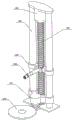
FIG. 1 is a schematic diagram of the present invention.
Fig. 2 is a schematic view of the regulating part of the present invention.
Fig. 3 is a schematic view of the present invention in use (telescoping).
Fig. 4 is a schematic view of a rotating portion according to the present invention.
FIG. 5 is a cross-sectional view of FIG. 4 in accordance with the present invention.
FIG. 6 is a rotated view of FIG. 5 in accordance with the present invention.
Fig. 7 is a schematic view of another rotating portion according to the present invention.
FIG. 8 is a cross-sectional view of FIG. 7 in accordance with the present invention.
Fig. 9 is a rotated view of fig. 8 in accordance with the present invention.
FIG. 10 is a schematic illustration of the process section of the present invention.
Fig. 11 is a schematic view of a nicking tool of the present invention.
Detailed Description
As shown in fig. 1 to 11, a six-axis engraving machine includes an up-down moving frame 400 supported on a sliding rail 200, the moving frame 400 and a screw 300 constitute a screw lifting mechanism, and a screw driving motor 100 is disposed at the upper part of the screw 300 and rotatably connected to the screw 400; an adjusting part 500 is fixed on the moving frame 400, and a nicking tool driven by a motor is fixed on the adjusting part 500; slide rail 200 bottom one side sets up carousel 600, regulating part 500 includes pars contractilis 510 and rotating part 520, and pars contractilis 510 is the base 512 fix electric putter on removing frame 400, and rotating part 520 is fixed on electric putter's telescopic link 511, is connected through first hollow disc stepper motor between telescopic link 511 and the rotating part 520.
The telescopic rod 511 is connected with the rotating part (520) through a first hollow disc-shaped stepping motor, and specifically comprises: the end of the extension rod 511 of the electric putter is fixed to the housing of the first hollow disc-shaped stepping motor, the output shaft tube 524 of the first hollow disc-shaped stepping motor is fixed to the inner wall of the rotary tube 521 of the rotary part 520, the contact surface of the electric putter and the rotary tube 521 is perpendicular to the axis of the electric putter and the rotary tube 521, and when the first hollow disc-shaped stepping motor rotates, the rotary tube 521 rotates relative to the electric putter.
The front end of the rotary pipe 521 is in contact connection with the rear end face of the operation pipe 523, specifically: the rear end surface of the working pipe 523 and the front end surface of the rotating pipe 521 are a second contact surface, the second contact surface and the axes of the rotating pipe 521 and the working pipe 523 are acute angles, the inner wall of the rear end of the working pipe 523 is fixed with the shell of the second hollow disc-shaped stepping motor, the output shaft pipe 525 of the second hollow disc-shaped stepping motor is fixed on the inner wall of the front end of the rotating pipe 521, and when the second hollow disc-shaped stepping motor rotates, the included angle of the axes between the working pipe 523 and the rotating pipe 521 is changed. As shown in fig. 5 and 6, the variation range is 0 to 180 degrees, the sum of the included angle between the second contact surface and the axis of the rotary pipe 521 and the included angle between the second contact surface and the axis of the working pipe 523 is subtracted, and when the included angle between the second contact surface and the axis of the rotary pipe 521 and the included angle between the second contact surface and the axis of the working pipe 523 are both small enough, the hollow disc-shaped stepping motor is combined to rotate, so that most of the inner spherical surface can be carved.
Set up crooked pipe 522 between the front end of rotatory pipe 521 and the rear end face of operation pipe 523, the front end of rotatory pipe 521 is connected with the rear end face contact of crooked pipe 522, specifically is: the rear end surface of the curved pipe 522 and the front end surface of the rotary pipe 521 are third contact surfaces, the third contact surfaces and the axes of the rotary pipe 521 and the operation pipe 523 are all acute angles, a housing of a third hollow disc-shaped stepping motor is fixed on the inner wall of the rear end of the operation pipe 523, an output shaft 526 of the third hollow disc-shaped stepping motor is fixed on the inner wall of the front end of the rotary pipe 521, and when the third hollow disc-shaped stepping motor rotates, the included angle of the axes between the operation pipe 523 and the rotary pipe 521 is changed.
The front end face of the bent pipe 522 is in surface contact with the rear end face of the operation pipe, specifically: the contact surface and the axes of the bending pipe 522 and the working pipe 523 are acute angles, the shell of the fourth hollow disc-shaped stepping motor is fixed on the inner wall of the front end of the bending pipe 522, the output shaft tube 527 of the fourth hollow disc-shaped stepping motor is fixed on the inner wall of the rear end of the working pipe 523, and when the fourth hollow disc-shaped stepping motor rotates, the axis included angle between the working pipe 523 and the bending pipe 522 is changed; the third hollow disc-shaped stepper motor is combined with the fourth hollow disc-shaped stepper motor, as shown in fig. 8 and 9, the range of variation is 0 to 180 degrees, and the third hollow disc-shaped stepper motor and the fourth hollow disc-shaped stepper motor rotate, so that most of the inner ball surface can be engraved.
The carving motor 532 is fixed in the hollow part in the operation pipe 523, the output shaft 533 of the carving motor 532 fixes the clamping mechanism 535 for clamping the rod handle of the grinding head, and the bearing 534 is fixed between the clamping mechanism 535 and the inner wall of the operation pipe 523.
The turntable is driven by a turntable motor 700.
The first stepping motor, the second stepping motor, the third stepping motor and the fourth stepping motor are servo motors.
As shown in fig. 6, the grinding head is a stone grinding rod 541, a pointed rod 542, and a hooked lump rod 543. The graver portion of the stone grinder 541 is columnar, and the outer end portion thereof is smoothly transited; the nicking tool portion of the pointed rod 542 is tapered; the graver part of the lump hooking rod 543 is in a cake shape. This is prior art.
When the carving machine works specifically, all the motors are connected with the PLC, a fixed carving program is set, a proper carving knife is selected to be fixed on an output shaft of the carving motor, and different motor drives are selected according to different carving objects and carving positions. During carving, the carved object is placed on the rotary table, during rough carving, the rotary part is adjusted to be linear, the electric push rod is adjusted to stretch, and the adjusting frame is adjusted to move up and down to realize rough carving; during the finishing impression, rotate the lateral wall of the glyptic slot of angle of difference with the rotating part, carve the cavity through adjustment pars contractilis earlier during the sculpture cavity, the rotating part can collude back the sculpture and import the inside wall.
The foregoing is only a preferred embodiment of the present invention, and it should be noted that, for those skilled in the art, various changes and modifications can be made without departing from the overall concept of the present invention, and these should also be considered as the protection scope of the present invention.

Claims (5)

1.一种六轴雕刻机,包括支撑在滑轨(200)上的上下移动架(400),移动架(400)与螺杆(300)构成丝杠升降机构,其特征在于:所述螺杆(300)上部设置驱动螺杆电机(100)与螺杆(400)转动连接;所述移动架(400)上固定调节部(500),调节部(500)上固定由电机带动的刻刀;所述滑轨(200)底部一侧设置转盘(600),所述调节部(500)包括伸缩部(510)和旋转部(520),伸缩部(510)为底座(512)固定在移动架(400)上电动推杆,旋转部(520)固定在电动推杆的伸缩杆(511)上,伸缩杆(511)与旋转部(520)之间通过第一空心盘状步进电机连接。1. A six-axis engraving machine, comprising an up and down moving frame (400) supported on a slide rail (200), the moving frame (400) and a screw (300) constitute a lead screw lifting mechanism, characterized in that: the screw ( 300) A driving screw motor (100) is arranged on the upper part to be rotatably connected with the screw rod (400); an adjusting part (500) is fixed on the moving frame (400), and a carving knife driven by the motor is fixed on the adjusting part (500); A turntable (600) is arranged on one side of the bottom of the rail (200), the adjusting part (500) includes a telescopic part (510) and a rotating part (520), and the telescopic part (510) is a base (512) fixed to the moving frame (400) On the electric push rod, the rotating part (520) is fixed on the telescopic rod (511) of the electric push rod, and the telescopic rod (511) and the rotating part (520) are connected by a first hollow disc-shaped stepping motor. 2.根据权利要求1所述的六轴雕刻机,其特征在于:所述伸缩杆(511)与旋转部(520)之间通过第一空心盘状步进电机连接,具体为:电动推杆的伸缩杆(511端部固定第一空心盘状步进电机的壳体,第一空心盘状步进电机的输出轴管(524)固定旋转部(520)的旋转管(521)内壁上,电动推杆与旋转管(521)的接触面与二者的轴线垂直,当第一空心盘状步进电机旋转时,使旋转管(521)相对于电动推杆转动;旋转管(521)的前端与作业管(523)的后端面接触连接,具体为:作业管(523)的后端面与旋转管(521)的前端面为第二接触面,第二接触面与旋转管(521)和作业管(523)的轴线都为锐角,作业管(523)后端的内壁上固定第二空心盘状步进电机的壳体,第二空心盘状步进电机的输出轴管(525)固定旋转管(521)的前端内壁上,当第二空心盘状步进电机旋转时,使作业管(523)与旋转管(521)之间轴线的夹角变动。2 . The six-axis engraving machine according to claim 1 , wherein the telescopic rod ( 511 ) and the rotating part ( 520 ) are connected by a first hollow disc-shaped stepping motor, specifically: an electric push rod The end of the telescopic rod (511) is fixed to the casing of the first hollow disc-shaped stepping motor, and the output shaft tube (524) of the first hollow disc-shaped stepping motor is fixed to the inner wall of the rotating tube (521) of the rotating part (520), The contact surface between the electric push rod and the rotating tube (521) is perpendicular to the axis of the two, and when the first hollow disc-shaped stepping motor rotates, the rotating tube (521) is rotated relative to the electric push rod; The front end is in contact and connection with the rear end surface of the working tube (523), specifically: the rear end surface of the working tube (523) and the front end surface of the rotating tube (521) are the second contact surface, and the second contact surface is connected with the rotating tube (521) and the rotating tube (521). The axes of the working tube (523) are all acute angles, the inner wall of the rear end of the working tube (523) is fixed with the casing of the second hollow disc-shaped stepping motor, and the output shaft tube (525) of the second hollow disc-shaped stepping motor is fixed and rotated On the inner wall of the front end of the pipe (521), when the second hollow disc-shaped stepping motor rotates, the included angle of the axis between the working pipe (523) and the rotating pipe (521) changes. 3.根据权利要求2所述的六轴雕刻机,其特征在于:所述旋转管(521)的前端与作业管(523)的后端面之间设置弯曲管(522),旋转管(521)的前端与弯曲管(522)的后端面接触连接,具体为:弯曲管(522)的后端面与旋转管(521)的前端面为第三接触面,第三接触面与旋转管(521)和作业管(523)的轴线都为锐角,作业管(523)后端的内壁上固定第三空心盘状步进电机的壳体,第三空心盘状步进电机的输出轴(526)管固定旋转管(521)的前端内壁上,当第三空心盘状步进电机旋转时,使作业管(523)与旋转管(521)之间轴线的夹角变动;3. The six-axis engraving machine according to claim 2, wherein a curved pipe (522) is arranged between the front end of the rotating pipe (521) and the rear end surface of the working pipe (523), and the rotating pipe (521) The front end of the bending tube (522) is in contact with the rear end surface of the bending tube (522), specifically: the rear end surface of the bending tube (522) and the front end surface of the rotating tube (521) are the third contact surface, and the third contact surface and the rotating tube (521) The axis of the working tube (523) is at an acute angle, the inner wall of the rear end of the working tube (523) is fixed with the casing of the third hollow disc-shaped stepping motor, and the output shaft (526) of the third hollow disc-shaped stepping motor is fixed on the tube. On the inner wall of the front end of the rotating pipe (521), when the third hollow disc-shaped stepping motor rotates, the included angle of the axis between the working pipe (523) and the rotating pipe (521) is changed; 弯曲管(522)的前端面与作业管(523)的后端面面接触,具体为:该接触面与弯曲管(522)和作业管(523)的轴线都为锐角,弯曲管(522)的前端内壁上固定第四空心盘状步进电机的壳体,第四空心盘状步进电机的输出轴管(527)固定作业管(523)后端的内壁上,当第四空心盘状步进电机旋转时,使作业管(523)与弯曲管(522)之间的轴线夹角变动;The front end surface of the curved pipe (522) is in surface contact with the rear end surface of the working pipe (523), specifically: the contact surface is at an acute angle with the axes of the curved pipe (522) and the working pipe (523). The housing of the fourth hollow disc-shaped stepping motor is fixed on the inner wall of the front end, and the output shaft tube (527) of the fourth hollow disc-shaped stepping motor is fixed on the inner wall of the rear end of the working tube (523). When the motor rotates, the axis angle between the working tube (523) and the bending tube (522) is changed; 作业管523内的空心部固定雕刻电机532,雕刻电机532的输出轴533固定夹持机535构用于夹持削磨头的杆柄,夹持机构535与作业管523内壁之间固定轴承534。The hollow part in the working tube 523 fixes the engraving motor 532 , the output shaft 533 of the engraving motor 532 fixes the clamping machine 535 for clamping the shank of the grinding head, and the bearing 534 is fixed between the clamping mechanism 535 and the inner wall of the working tube 523 . 4.根据权利要求3所述的六轴雕刻机,其特征在于:所述转盘由转盘电机(700)带动。4. The six-axis engraving machine according to claim 3, wherein the turntable is driven by a turntable motor (700). 5.根据权利要求4所述的六轴雕刻机,其特征在于:所述第一步进电机、第二步进电机、第三步进电机、第四步进电机为伺服电机。5 . The six-axis engraving machine according to claim 4 , wherein the first stepper motor, the second stepper motor, the third stepper motor and the fourth stepper motor are servo motors. 6 .
CN201911386915.XA 2019-12-29 2019-12-29 Six engravers Active CN110920305B (en)

Priority Applications (1)

Application Number Priority Date Filing Date Title
CN201911386915.XA CN110920305B (en) 2019-12-29 2019-12-29 Six engravers

Applications Claiming Priority (1)

Application Number Priority Date Filing Date Title
CN201911386915.XA CN110920305B (en) 2019-12-29 2019-12-29 Six engravers

Publications (2)

Publication Number Publication Date
CN110920305A true CN110920305A (en) 2020-03-27
CN110920305B CN110920305B (en) 2022-02-22

Family

ID=69861229

Family Applications (1)

Application Number Title Priority Date Filing Date
CN201911386915.XA Active CN110920305B (en) 2019-12-29 2019-12-29 Six engravers

Country Status (1)

Country Link
CN (1) CN110920305B (en)

Citations (6)

* Cited by examiner, † Cited by third party
Publication number Priority date Publication date Assignee Title
EP0634818A2 (en) * 1993-07-12 1995-01-18 Sumitomo Wiring Systems, Ltd. Charge coupling for electric vehicle
CN103231616A (en) * 2013-04-23 2013-08-07 青岛速霸数控设备有限公司 Three-dimensional art carving machine
CN205905628U (en) * 2016-07-07 2017-01-25 莆田市秀屿区铭星阁石雕有限公司 A multifunctional stone carving machine
CN206066317U (en) * 2016-09-27 2017-04-05 刘勉群 Mini electric screwdriver
CN106626922A (en) * 2016-12-13 2017-05-10 林方杰 An engraving machine for engraving the inner wall of a container
CN108311092A (en) * 2018-04-19 2018-07-24 黄河科技学院 Consistent charging tumble mixed agitating device

Patent Citations (6)

* Cited by examiner, † Cited by third party
Publication number Priority date Publication date Assignee Title
EP0634818A2 (en) * 1993-07-12 1995-01-18 Sumitomo Wiring Systems, Ltd. Charge coupling for electric vehicle
CN103231616A (en) * 2013-04-23 2013-08-07 青岛速霸数控设备有限公司 Three-dimensional art carving machine
CN205905628U (en) * 2016-07-07 2017-01-25 莆田市秀屿区铭星阁石雕有限公司 A multifunctional stone carving machine
CN206066317U (en) * 2016-09-27 2017-04-05 刘勉群 Mini electric screwdriver
CN106626922A (en) * 2016-12-13 2017-05-10 林方杰 An engraving machine for engraving the inner wall of a container
CN108311092A (en) * 2018-04-19 2018-07-24 黄河科技学院 Consistent charging tumble mixed agitating device

Also Published As

Publication number Publication date
CN110920305B (en) 2022-02-22

Similar Documents

Publication Publication Date Title
CN112497978B (en) A device for engraving texture on the surface of a handicraft body
CN110920305B (en) Six engravers
CN112792709A (en) Die arc-shaped groove polishing device
CN216577035U (en) Gear shaft production is with grinding device who has positioning mechanism
CN107671994A (en) Digital controlled ceramic blank forming machine and its moulding process
CN211761563U (en) Multi-joint robot engraving machine
CN209380270U (en) A kind of numerical control grinding processing unit (plant)
CN219426362U (en) Polishing device for stopper rod production
CN218053357U (en) Novel stone carving table
CN103419285B (en) Processing method of hollow stone container
CN216463735U (en) A multi-head grinding blank device for ceramic processing
CN117206695A (en) cup engraving machine
CN217860645U (en) Surface polishing device for 3D engraving finished product
CN110154605B (en) Full-automatic engraving system and method for art stamp
CN220783707U (en) A product design positioning device
CN210255554U (en) A segmented grinding tool for supporting a thimble
CN217702897U (en) Angle-adjustable mold blank surface polishing device
CN221584984U (en) Industrial numerical control double-shaft engraving machine
CN224042822U (en) Positioning tool of laser engraving machine
CN213196907U (en) Lifting type rotary polishing machine tool
CN214641347U (en) Laser engraving machine with positioning and clamping functions
CN217860609U (en) A fettling device for ceramic machining usefulness
CN220904513U (en) Building decoration gypsum processingequipment
CN223406735U (en) A grinding and polishing device for mechanical gear processing
CN205166632U (en) Automatic burnishing machine of glass mold appearance

Legal Events

Date Code Title Description
PB01 Publication
PB01 Publication
SE01 Entry into force of request for substantive examination
GR01 Patent grant
GR01 Patent grant
TR01 Transfer of patent right

Effective date of registration: 20250227

Address after: 450000 Southwest of Feilong Road and Zhannan Road Intersection, Xingyang City, Zhengzhou City, Henan Province

Patentee after: ZHENGZHOU SHENTONG CULTURAL TOURISM TECHNOLOGY CO.,LTD.

Country or region after: China

Address before: 450015 Middle Road, 27 District University, Zhengzhou, Henan Province, No. 2

Patentee before: ZHENGZHOU INSTITUTE OF AERONAUTICAL INDUSTRY MANAGEMENT

Country or region before: China

TR01 Transfer of patent right