Seabed tripod observation system
Technical Field
The invention relates to a submarine tripod observation system, and belongs to the field of deep sea detection equipment.
Background
The deep water heavy load carrying equipment is equipment for carrying out in-situ observation on a deep sea floor of 6000 meters. The open structure design of the device can bear various instruments such as acoustics, optics and the like with high precision and high frequency, the falling bottom is stable, and the long-term, stable and self-contained in-situ observation is carried out on the physical, chemical, geological and biological parameters of the bottom boundary layer. Instruments such as TELEDYNE R12K acoustic releasers, NORTEK acoustic Doppler velocimeters, NORTEK acoustic Doppler profile velocimeters and RBR warm salt deep corrosion meters carried by deep water heavy-load carrying equipment in the prior art are expensive and need to be placed and recovered safely. In order to keep the stability of the deep water heavy-load carrying equipment on the seabed, a 2.5-ton tripod is carried below the deep water heavy-load carrying equipment, so that the deep water heavy-load carrying equipment is difficult to recover in the recovery process, and all the recovery buoyancy needs to be provided through hoisting equipment, so that the recovery difficulty of the deep water heavy-load carrying equipment is caused.
Disclosure of Invention
The technical scheme of the invention aims at the following problems in the prior art: in order to keep the stability of the deepwater heavy-load carrying equipment on the seabed, a 2.5-ton tripod is carried below the deepwater heavy-load carrying equipment, so that the deepwater heavy-load carrying equipment is difficult to recover in the recovery process, all the recovery buoyancy is required to be provided through hoisting equipment, and the defect that the deepwater heavy-load carrying equipment is difficult to recover is overcome.
In order to solve the technical problem, the invention adopts the technical scheme that the submarine tripod observation system comprises an acoustic Doppler profile flow meter (1), an acoustic Doppler flow meter (2), a thermohaline deep corrosion meter (3) and a disc-shaped floating body (5), wherein an inner through hole penetrating through the floating body (5) is formed in the middle of the floating body (5), and an upper end opening and a lower end opening of the inner through hole are respectively formed in the upper surface and the lower surface of the disc of the floating body (5); the acoustic Doppler current meter (2) and the thermohaline deep corrosion meter (3) are arranged on the side part of the floating body (5) and are fixedly connected with the floating body (5); annular cover plates (7) are respectively arranged on the upper surface and the lower surface of the floating body (5), a connecting rod (11) is arranged between the cover plates (7) on the upper surface and the lower surface of the floating body (5), and two ends of the connecting rod (11) are respectively fixedly connected with the cover plates (7) on the upper surface and the lower surface of the floating body (5) through nuts; an upper pull frame left (8) and an upper pull frame right (9) are fixedly arranged on the cover plate (7) on the upper surface of the floating body (5), the upper pull frame left (8) and the upper pull frame right (9) are both U-shaped, and U-shaped openings of the upper pull frame left (8) and the upper pull frame right (9) face the cover plate (7) on the upper surface of the floating body (5); the acoustic Doppler profile current meter (1) penetrates through an inner through hole of the floating body (5) and is fixedly connected with the left upper pulling frame (8) and the right upper pulling frame (9), the left upper pulling frame (8) and the right upper pulling frame (9) are respectively connected with a shackle (13), and the two shackles (13) are connected with a release hook (14); a tripod (24) is arranged below the floating body (5), and the tripod (24) is fixedly connected with the floating body (5).
According to the technical scheme, the acoustic Doppler profile current meter (1), the acoustic Doppler current meter (2) and the warm salt deep corrosion meter (3) are fixedly arranged on the floating body (5), the floating body (5) can provide positive buoyancy for the whole equipment, and the deep water heavy-load floating body carrying device is guaranteed to provide enough buoyancy for the deep water heavy-load floating body carrying device to be recovered after the acoustic deck unit is released after a task is completed. The buoyancy of the float (5) can be varied by varying the volume of the float (5). The inner through hole penetrating through the floating body (5) arranged on the floating body (5) plays a role in guiding, and when the deep water heavy-load floating body carrying device is placed on the seabed, water flows pass through the inner through hole and are discharged through the inner through hole, so that the function of guiding is played, the deep water heavy-load floating body carrying device is prevented from being deviated in the process of being placed below the deep water heavy-load floating body carrying device as far as possible, and the deep water heavy-load floating body carrying device is ensured to be placed at a preset position. The tripod (24) is hung below the floating body (5) and is used as the integral counterweight of the deep water heavy-load floating body carrying device.
Preferably, the seabed tripod observation system is characterized in that the floating body (5) is provided with a plurality of flow guide holes (30) penetrating through the floating body (5), openings at two ends of each flow guide hole (30) are respectively located on the upper surface and the lower surface of the floating body (5), the length extending direction of each flow guide hole (30) is perpendicular to the upper surface and the lower surface of the floating body (5), and all the flow guide holes (30) are annularly arranged around the inner through hole.
In the application, the guide holes (30) which are annularly arranged around the inner through hole are formed in the floating body (5), and in the process of lowering the deep-water heavy-load floating body carrying device, seawater flows through the guide holes (30) to play a role in guiding, so that the deep-water heavy-load floating body carrying device is kept stable as much as possible in the lowering process, and the deviation is prevented.
Optimized, above-mentioned seabed tripod observation system, be provided with base (6) on apron (7) of body (5) lower surface, be provided with a holding tank on body (5) lower surface, base (6) are located the holding tank on body (5) lower surface, base (6) and body (5) lower surface apron (7) fixed connection, be provided with a plurality of pillars (10) in body (5), the both ends of pillar (10) pass through nut fixed connection with apron (7) of base (6), body (5) upper surface respectively.
In the application, the base (6) is connected with the cover plate (7) on the upper surface of the floating body (5) through the support column (10), so that the connection firmness between the cover plate (7) on the upper surfaces of the base (6) and the floating body (5) is improved, the fixing firmness of the shackle (13) and the release hook (14) connected to the cover plate (7) on the upper surface of the floating body (5) is further improved, and the stability of the deepwater heavy-load floating body carrying device during hoisting by using the shackle (13) and the release hook (14) is ensured.
Preferably, in the submarine tripod observation system, the U-shaped opening of the left upper pulling frame (8) and the U-shaped opening of the right upper pulling frame (9) are respectively provided with a connecting plate, the connecting plates are attached to the cover plate (7) on the upper surface of the floating body (5), a plurality of screw rods (11) are arranged between the cover plates (7) on the upper surfaces of the base (6) and the floating body (5), and the two ends of each screw rod (11) respectively penetrate through the cover plates (7) on the upper surfaces of the base (6) and the floating body (5) and are fixed through nuts.
In this application, the connecting plate of the left (8) and right (9) upper pull frames is directly fixed with the cover plate (7) on the upper surface of the base (6) and the floating body (5) through the screw (11), so that the fixing firmness of the left (8) and right (9) upper pull frames is ensured, and the deep water heavy-load floating body carrying device has better stability when being hoisted by using the shackle (13) and the release hook (14).
Preferably, the seabed tripod observation system is characterized in that two acoustic releasers (4) are arranged in the floating body (5), the upper ends of the acoustic releasers (4) are fixedly connected with the left upper pull frame (8) and the right upper pull frame (9) through screws, and the lower ends of the acoustic releasers (4) are fixedly connected with the base (6) through stud screws.
In this application, because acoustics releaser (4) need reduce as far as when releasing the sound wave and shelter from, so set up acoustics releaser (4) in the inside through-hole of body (5), the upper end of acoustics releaser (4) is fixed in on the pull-up frame left (8), pull-up frame right (9), the lower extreme of acoustics releaser (4) is fixed in on base (6), make acoustics releaser (4) have better stability, it takes place the skew to reduce acoustics releaser (4) and transfer the in-process.
Preferably, in the submarine tripod observation system, a support (21) is arranged between the cover plate (7) on the upper surface of the floating body (5) and the base (6), two ends of the support (21) are respectively and fixedly connected with the base (6) and the cover plate (7) on the upper surface of the floating body (5), the lower end of the support (21) is fixedly connected with a hanging ring (18), four hanging points are arranged on the side surface of the hanging ring (18), and the four hanging points are uniformly distributed around the hanging ring (18) in an annular shape; the hanging ring (18) is fixedly connected with two anchor chains (17), one ends of the two anchor chains (17) are hung on two symmetrically-arranged hanging points on the hanging ring (18) respectively, and the other ends of the anchor chains (17) are hung on the acoustic releaser (4).
In the application, a bracket (21) is fixed between a cover plate (7) on the upper surface of a floating body (5) and a base (6), and an acoustic releaser (4) is fixed on a hanging ring (18) of the bracket (21) through an anchor chain (17). The lower end of the acoustic releaser (4) is stabilized through the support (21), the stability of the acoustic releaser (4) is improved, and the stability of an anchor chain (17) and a hanging ring (18) hung at the lower end of the acoustic releaser (4) can be improved.
Preferably, the seabed tripod observation system is provided with three counterweights (12) on the floating body (5), wherein the counterweights (12) are uniformly distributed along the annular outer side surface of the floating body (5) in a circular shape and are fixedly connected with the floating body (5), the acoustic Doppler current meter (2) and the thermohaline deep corrosion meter (3) are respectively fixedly connected with the end parts of two of the counterweights (12), and the end part of the other one of the counterweights (12) is fixedly connected with a counterweight block.
In the application, the acoustic Doppler current meter (2) and the warm salt deep corrosion meter (3) are connected to the annular outer side face of the floating body (5) through the balance weight (12), the balance weight (12) increases the stability of the floating body (5), and as no hanging equipment is arranged on one balance weight (12), a distributing block is hung to stabilize the gravity center of the floating body (5), so that the gravity center of the deep water heavy-load floating body carrying device is maintained on the axis as much as possible, and the balance of the whole deep water heavy-load floating body carrying device under water is guaranteed.
Preferably, in the submarine tripod observation system, the counterweight (12) is a U-shaped bending rod, and two ends of a U-shaped opening of the counterweight (12) are respectively and fixedly connected with the base (6) and the cover plate (7) on the upper surface of the floating body (5).
In this application, set up counter weight (12) into U type pole to it is fixed with apron (7) of base (6), body (5) upper surface respectively with the both ends of counter weight (12), makes counter weight (12) and body (5) have better firm in connection.
Preferably, the seabed tripod observation system is characterized in that the base (6) is provided with a plurality of threaded columns (28), the tripod (24) is provided with a plurality of long shaft pins (26) matched with the threaded columns (28), one ends of the long shaft pins (26) are fixedly welded with the tripod (24), and the other ends of the long shaft pins (26) are inserted into the threaded columns (28) and are in interference fit with the threaded columns (28).
In this application, long pivot (26) on tripod (24) are pegged graft in threaded column (28) for preliminary fixed is accomplished with body (5) to tripod (24), prevents that the position of tripod (24) from taking place dislocation skew between whereabouts in-process and body (5).
Preferably, in the submarine tripod observation system, the threaded column (28) is in threaded connection with a large nut (25); an annular boss is arranged on the long shaft pin (26), a belleville spring (27) is arranged between the boss of the long shaft pin (26) and the large nut (25), and the belleville spring (27) is in tight press contact with the lower end face of the large nut (25) and the upper end face of the long shaft pin (26); two U-shaped rings are arranged on the tripod (24), and two hanging points of the hanging ring (18) are inserted into the U-shaped rings.
In this application, tripod (24) are still through link (18), anchor chain (17) and body (5) fixed connection, improve the firm in connection degree of tripod (24). The large nut (25) is rotated to enable the large nut (25) to extrude the belleville spring (27), the long shaft pin (26) is pressed down through the pressure of the belleville spring (27), the tripod (24) is further pressed down, the anchor chain (17) is tightened after the tripod (24) is pressed down, and the shaking of the tripod (24) is reduced.
Drawings
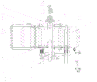
FIG. 1 is a schematic structural view of the present invention;
FIG. 2 is a top view of FIG. 1;
FIG. 3 is a cross-sectional view C-C of FIG. 1;
FIG. 4 is a cross-sectional view B-B of FIG. 2;
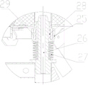
FIG. 5 is an enlarged view at Q of FIG. 3;
fig. 6 is a cross-sectional view taken along line D-D of fig. 1.
Detailed Description
The technical features of the present invention will be further explained with reference to the accompanying drawings and specific embodiments.
As shown in the figure, the invention relates to a submarine tripod observation system which comprises an acoustic Doppler profile flow meter (1), an acoustic Doppler flow meter (2), a thermohaline deep corrosion meter (3) and a disc-shaped floating body (5), wherein the middle part of the floating body (5) is provided with an internal through hole penetrating through the floating body (5), and an upper end opening and a lower end opening of the internal through hole are respectively arranged on the upper surface and the lower surface of the disc of the floating body (5); the acoustic Doppler current meter (2) and the thermohaline deep corrosion meter (3) are arranged on the side part of the floating body (5) and are fixedly connected with the floating body (5); annular cover plates (7) are respectively arranged on the upper surface and the lower surface of the floating body (5), a connecting rod (11) is arranged between the cover plates (7) on the upper surface and the lower surface of the floating body (5), and two ends of the connecting rod (11) are respectively fixedly connected with the cover plates (7) on the upper surface and the lower surface of the floating body (5) through nuts; an upper pull frame left (8) and an upper pull frame right (9) are fixedly arranged on the cover plate (7) on the upper surface of the floating body (5), the upper pull frame left (8) and the upper pull frame right (9) are both U-shaped, and U-shaped openings of the upper pull frame left (8) and the upper pull frame right (9) face the cover plate (7) on the upper surface of the floating body (5); the acoustic Doppler profile current meter (1) penetrates through an inner through hole of the floating body (5) and is fixedly connected with the left upper pulling frame (8) and the right upper pulling frame (9), the left upper pulling frame (8) and the right upper pulling frame (9) are respectively connected with a shackle (13), and the two shackles (13) are connected with a release hook (14); a tripod (24) is arranged below the floating body (5), and the tripod (24) is fixedly connected with the floating body (5).
According to the technical scheme, the acoustic Doppler profile current meter (1), the acoustic Doppler current meter (2) and the warm salt deep corrosion meter (3) are fixedly arranged on the floating body (5), the floating body (5) can provide positive buoyancy for the whole equipment, and the deep water heavy-load floating body carrying device is guaranteed to provide enough buoyancy for the deep water heavy-load floating body carrying device to be recovered after the acoustic deck unit is released after a task is completed. The buoyancy of the float (5) can be varied by varying the volume of the float (5). The inner through hole penetrating through the floating body (5) arranged on the floating body (5) plays a role in guiding, and when the deep water heavy-load floating body carrying device is placed on the seabed, water flows pass through the inner through hole and are discharged through the inner through hole, so that the function of guiding is played, the deep water heavy-load floating body carrying device is prevented from being deviated in the process of being placed below the deep water heavy-load floating body carrying device as far as possible, and the deep water heavy-load floating body carrying device is ensured to be placed at a preset position. The tripod (24) is hung below the floating body (5) and is used as the integral counterweight of the deep water heavy-load floating body carrying device.
A plurality of flow guide holes (30) penetrating through the floating body (5) are formed in the floating body (5), openings in two ends of each flow guide hole (30) are respectively located on the upper surface and the lower surface of the floating body (5), the length extending direction of each flow guide hole (30) is perpendicular to the upper surface and the lower surface of the floating body (5), and all the flow guide holes (30) are annularly arranged around the inner through holes.
In the application, the guide holes (30) which are annularly arranged around the inner through hole are formed in the floating body (5), and in the process of lowering the deep-water heavy-load floating body carrying device, seawater flows through the guide holes (30) to play a role in guiding, so that the deep-water heavy-load floating body carrying device is kept stable as much as possible in the lowering process, and the deviation is prevented.
Be provided with base (6) on apron (7) of body (5) lower surface, be provided with a holding tank on body (5) lower surface, base (6) are located the holding tank on body (5) lower surface, and base (6) and body (5) lower surface's apron (7) fixed connection, be provided with a plurality of pillars (10) in body (5), the both ends of pillar (10) pass through nut fixed connection with apron (7) of base (6), body (5) upper surface respectively.
In the application, the base (6) is connected with the cover plate (7) on the upper surface of the floating body (5) through the support column (10), so that the connection firmness between the cover plate (7) on the upper surfaces of the base (6) and the floating body (5) is improved, the fixing firmness of the shackle (13) and the release hook (14) connected to the cover plate (7) on the upper surface of the floating body (5) is further improved, and the stability of the deepwater heavy-load floating body carrying device during hoisting by using the shackle (13) and the release hook (14) is ensured.
The U-shaped opening of the left upper pull frame (8) and the U-shaped opening of the right upper pull frame (9) are respectively provided with a connecting plate, the connecting plates are attached to a cover plate (7) on the upper surface of the floating body (5), a plurality of screw rods (11) are arranged between the cover plates (7) on the upper surfaces of the base (6) and the floating body (5), and two ends of each screw rod (11) respectively penetrate through the cover plates (7) on the upper surfaces of the base (6) and the floating body (5) and are fixed through nuts.
In this application, the connecting plate of the left (8) and right (9) upper pull frames is directly fixed with the cover plate (7) on the upper surface of the base (6) and the floating body (5) through the screw (11), so that the fixing firmness of the left (8) and right (9) upper pull frames is ensured, and the deep water heavy-load floating body carrying device has better stability when being hoisted by using the shackle (13) and the release hook (14).
Two acoustic releasers (4) are arranged in the floating body (5), the upper ends of the acoustic releasers (4) are fixedly connected with the left upper pull frame (8) and the right upper pull frame (9) through screws, and the lower ends of the acoustic releasers (4) are fixedly connected with the base (6) through stud screws.
In this application, because acoustics releaser (4) need reduce as far as when releasing the sound wave and shelter from, so set up acoustics releaser (4) in the inside through-hole of body (5), the upper end of acoustics releaser (4) is fixed in on the pull-up frame left (8), pull-up frame right (9), the lower extreme of acoustics releaser (4) is fixed in on base (6), make acoustics releaser (4) have better stability, it takes place the skew to reduce acoustics releaser (4) and transfer the in-process.
A bracket (21) is arranged between the cover plate (7) on the upper surface of the floating body (5) and the base (6), two ends of the bracket (21) are respectively and fixedly connected with the base (6) and the cover plate (7) on the upper surface of the floating body (5), the lower end of the bracket (21) is fixedly connected with a hanging ring (18), four hanging points are arranged on the side surface of the hanging ring (18), and the four hanging points are uniformly distributed around the hanging ring (18) in an annular shape; the hanging ring (18) is fixedly connected with two anchor chains (17), one ends of the two anchor chains (17) are hung on two symmetrically-arranged hanging points on the hanging ring (18) respectively, and the other ends of the anchor chains (17) are hung on the acoustic releaser (4).
In the application, a bracket (21) is fixed between a cover plate (7) on the upper surface of a floating body (5) and a base (6), and an acoustic releaser (4) is fixed on a hanging ring (18) of the bracket (21) through an anchor chain (17). The lower end of the acoustic releaser (4) is stabilized through the support (21), the stability of the acoustic releaser (4) is improved, and the stability of an anchor chain (17) and a hanging ring (18) hung at the lower end of the acoustic releaser (4) can be improved.
The floating body (5) is provided with three balance weights (12), the balance weights (12) are uniformly distributed in a circular shape along the outer side surface of the floating body (5) and are fixedly connected with the floating body (5), the acoustic Doppler current meter (2) and the thermohaline deep corrosion meter (3) are respectively fixedly connected with the end parts of the two balance weights (12), and the end part of the other balance weight (12) is fixedly connected with a balance weight.
In the application, the acoustic Doppler current meter (2) and the warm salt deep corrosion meter (3) are connected to the annular outer side face of the floating body (5) through the balance weight (12), the balance weight (12) increases the stability of the floating body (5), and as no hanging equipment is arranged on one balance weight (12), a distributing block is hung to stabilize the gravity center of the floating body (5), so that the gravity center of the deep water heavy-load floating body carrying device is maintained on the axis as much as possible, and the balance of the whole deep water heavy-load floating body carrying device under water is guaranteed.
The counterweight (12) is a U-shaped bending rod, and two ends of a U-shaped opening of the counterweight (12) are respectively fixedly connected with the base (6) and the cover plate (7) on the upper surface of the floating body (5).
In this application, set up counter weight (12) into U type pole to it is fixed with apron (7) of base (6), body (5) upper surface respectively with the both ends of counter weight (12), makes counter weight (12) and body (5) have better firm in connection.
The base (6) is provided with a plurality of threaded columns (28), the tripod (24) is provided with a plurality of long shaft pins (26) matched with the threaded columns (28), one ends of the long shaft pins (26) are fixedly welded with the tripod (24), and the other ends of the long shaft pins (26) are inserted into the threaded columns (28) and are in interference fit with the threaded columns (28).
In this application, long pivot (26) on tripod (24) are pegged graft in threaded column (28) for preliminary fixed is accomplished with body (5) to tripod (24), prevents that the position of tripod (24) from taking place dislocation skew between whereabouts in-process and body (5).
A large nut (25) is connected to the threaded column (28) in a threaded manner; an annular boss is arranged on the long shaft pin (26), a belleville spring (27) is arranged between the boss of the long shaft pin (26) and the large nut (25), and the belleville spring (27) is in tight press contact with the lower end face of the large nut (25) and the upper end face of the long shaft pin (26); two U-shaped rings are arranged on the tripod (24), and two hanging points of the hanging ring (18) are inserted into the U-shaped rings.
In this application, tripod (24) are still through link (18), anchor chain (17) and body (5) fixed connection, improve the firm in connection degree of tripod (24). The large nut (25) is rotated to enable the large nut (25) to extrude the belleville spring (27), the long shaft pin (26) is pressed down through the pressure of the belleville spring (27), the tripod (24) is further pressed down, the anchor chain (17) is tightened after the tripod (24) is pressed down, and the shaking of the tripod (24) is reduced.
It is to be understood that the above description is not intended to limit the present invention, and the present invention is not limited to the above examples, and those skilled in the art should understand that they can make various changes, modifications, additions and substitutions within the spirit and scope of the present invention.