Automatic ore sorting equipment
Technical Field
The invention relates to the field of ore sorting, in particular to automatic ore sorting equipment.
Background
As is known, when metal ores are mined, the mined ores are pulled out by one vehicle, and transport vehicles can stack the ores together and then further sort the ores, but the existing sorting equipment has a plurality of equipment combinations, so that the working cost is very high, and therefore, the automatic ore sorting equipment needs to be designed to solve the problems.
Disclosure of Invention
The invention aims to provide automatic ore sorting equipment which is used for overcoming the defects in the prior art.
The invention is realized by the following technical scheme.
An automatic ore sorting apparatus comprising a housing, the housing comprising a vibrating chamber;
the vibration cavity is internally provided with a vibration mechanism, a first connecting rod which is bilaterally symmetrical is fixedly arranged at the left end in the vibration cavity, a second connecting rod is arranged in the first connecting rod in a sliding manner, a concave block is fixedly arranged on the inner end surface of the second connecting rod, a first spring is arranged in the concave block, a third connecting rod is fixedly arranged on the first spring, a second spring is fixedly arranged between the bottom end surface of the third connecting rod and the inner surface of the concave block, a fourth connecting rod is fixedly arranged on the top end surface of the third connecting rod in a bilaterally symmetrical manner, the fourth connecting rod penetrates through the first spring and the concave block, a vibration block is fixedly arranged in the third connecting rod, a first rotating shaft is hinged in the vibration block, a rotating block is fixedly arranged on the first rotating shaft, a sector block is fixedly arranged on the rotating block, a first belt pulley is fixedly arranged on the first rotating shaft at the front side of the rotating block, and a material, the front and the back of the material passing plate are symmetrically provided with leak-proof plates;
vibrations chamber right-hand member intercommunication is equipped with the ejection of compact chamber, the ejection of compact intracavity is equipped with discharge mechanism, the symmetry rotates about ejection of compact chamber top and is equipped with the second pivot, the fixed fifth connecting rod that is equipped with in front end in the second pivot, the fixed sixth connecting rod that is equipped with on the fifth connecting rod, the articulated seventh connecting rod that is equipped with on the sixth connecting rod, the fixed crushing pole that is equipped with between the seventh connecting rod, the fixed fragment of grinding that is equipped with on the crushing pole, ejection of compact chamber bottom is equipped with the spout, it is equipped with the slider to slide in the spout, slider bottom face with it is equipped with the third spring to connect between the spout, be equipped with a plurality of dress board on the slider, ejection of compact chamber left end is equipped with the ejection of compact slide left.
Further, a third rotating shaft is rotatably arranged on the right side of the vibration cavity, a motor is fixedly arranged in the rear end wall of the vibration cavity at the rear end of the third rotating shaft, the motor is in rotating fit with the third rotating shaft, a second belt pulley is fixedly arranged at the front end of the third rotating shaft, a first belt is rotatably arranged between the second belt pulley and the first belt pulley, a third belt pulley is arranged on the rear side of the third rotating shaft, a fourth rotating shaft is rotatably arranged on the right side of the third rotating shaft, a fourth belt pulley is fixedly arranged on the fourth rotating shaft, a fifth rotating shaft is rotatably arranged on the right side of the fourth rotating shaft, a fifth belt pulley is fixedly arranged on the fifth rotating shaft, a magnetic belt is rotatably arranged between the fourth belt pulley and the fifth belt pulley, a second belt is rotatably arranged between the magnetic belt and the third belt pulley, and a sixth belt pulley is fixedly arranged at the rear end of the third rotating shaft, the right end of the oscillation cavity is provided with a waste outlet.
Furthermore, a seventh belt pulley is fixed on the second rotating shaft at the rear side of the fifth connecting rod, a third belt is arranged between the seventh belt pulley in a vertical symmetrical mode, an eighth belt pulley is fixedly arranged at the rear end of the second rotating shaft, a fourth belt is arranged between the eighth belt pulley and the sixth belt pulley in a rotating mode, the rear side of the loading plate at the top end is provided with a left sixth rotating shaft and a right sixth rotating shaft in a rotating mode, a ninth belt pulley is fixedly arranged on the sixth rotating shaft at the rear side, a fifth belt is arranged between the ninth belt pulley and the eighth belt pulley at the lower side in a rotating mode, gears are arranged on the front section of the sixth rotating shaft in a fixed symmetrical mode, chains are arranged between the gears in a rotating mode in a bilateral symmetrical mode, and pushing blocks are arranged on the chains.
Further, the topmost loading plate and the discharge chute are at the same height.
Further, when the pushing block is positioned on the lower side of the chain, the loading plate can be pushed to slide leftwards in the discharging slide way.
The invention has the beneficial effects that: the vibrating type ore sorting machine is simple in structure and easy and convenient to operate, stacked ores can be firstly leveled through vibration so as to facilitate subsequent sorting, metal ores are sorted out through a magnetic belt in the device, then large ores are crushed and then are uniformly conveyed out, observation and collection are facilitated, the kinetic energy utilization rate and the working efficiency are high, and meanwhile, the degree of integration is high.
Drawings
In order to more clearly illustrate the embodiments of the invention or the technical solutions in the prior art, the drawings used in the description of the embodiments or the prior art will be briefly described below, and it is obvious that the drawings in the following description are only some embodiments of the invention, and it is obvious for those skilled in the art that other drawings can be obtained based on these drawings without creative efforts.
FIG. 1 is a schematic structural diagram of an embodiment of the present invention;
FIG. 2 is a schematic view of the structure A-A of FIG. 1;
FIG. 3 is a schematic diagram of B-B of FIG. 1;
fig. 4 is a schematic view of the structure of C-C in fig. 1.
Detailed Description
The invention will now be described in detail with reference to fig. 1-4, for convenience of description, the following orientations will now be defined: the up, down, left, right, and front-back directions described below correspond to the up, down, left, right, and front-back directions in the projection relationship of fig. 1 itself.
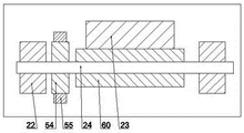
With reference to fig. 1-4, an automatic ore sorting device includes a housing 10, the housing 10 includes a vibration chamber 19, a vibration mechanism 90 is contained in the vibration chamber 19, a first connecting rod 12 with bilateral symmetry is fixed at the inner left end of the vibration chamber 19, a second connecting rod 14 is slidably arranged in the first connecting rod 12, a concave block 11 is fixed at the inner end surface of the second connecting rod 14, a first spring 15 is arranged in the concave block 11, a third connecting rod 20 is fixedly arranged on the first spring 15, a second spring 21 is fixedly arranged between the bottom end surface of the third connecting rod 20 and the inner surface of the concave block 11, a fourth connecting rod 16 is fixedly arranged at the top end surface of the third connecting rod 20 in a bilateral symmetry manner, the fourth connecting rod 16 passes through the first spring 15 and the concave block 11, a vibration block 22 is fixedly arranged in the third connecting rod 20, a first rotating shaft 24 is hinged in the vibration block 22, a rotating block 60 is fixedly arranged on the first rotating shaft 24, a sector block 23 is fixedly arranged on the rotating block 60, a first belt pulley 54 is fixedly arranged on the first rotating shaft 24 at the front side of the rotating block 60, a material passing plate 17 is fixedly arranged at the top end of the fourth connecting rod 16, and the material passing plate 17 is symmetrically provided with anti-leakage plates 18 in the front and back;
vibrations 19 right-hand member intercommunication in chamber is equipped with ejection of compact chamber 33, be equipped with discharge mechanism 91 in ejection of compact chamber 33, ejection of compact chamber 33 top longitudinal symmetry rotates and is equipped with second pivot 27, the fixed fifth connecting rod 28 that is equipped with in front end on the second pivot 27, fixed sixth connecting rod 29 that is equipped with on the fifth connecting rod 28, the articulated seventh connecting rod 30 that is equipped with on the sixth connecting rod 29, the fixed grinding rod 41 that is equipped with between the seventh connecting rod 30, the fixed grinding fragment 40 that is equipped with on the grinding rod 41, ejection of compact chamber 33 bottom is equipped with spout 34, it is equipped with slider 42 to slide in spout 34, slider 42 bottom face with connect between spout 34 and be equipped with third spring 43, be equipped with a plurality of dress goods board 32 on the slider 42, ejection of compact chamber 33 left end is equipped with open-ended ejection of compact slide 31 left.
The right side of the vibration cavity 19 is rotated to be provided with a third rotating shaft 26, the rear end wall of the vibration cavity 19 at the rear end of the third rotating shaft 26 is internally fixedly provided with a motor 59, the motor 59 is in running fit with the third rotating shaft 26, the front end of the third rotating shaft 26 is fixedly provided with a second belt pulley 56, a first belt 55 is arranged between the second belt pulley 56 and the first belt pulley 54 in a rotating way, the rear side of the third rotating shaft 26 is provided with a third belt pulley 25, the right side of the third rotating shaft 26 is rotated to be provided with a fourth rotating shaft 38, the fourth rotating shaft 38 is fixedly provided with a fourth belt pulley 37, the right side of the fourth rotating shaft 38 is rotated to be provided with a fifth rotating shaft 57, the fifth rotating shaft 57 is fixedly provided with a fifth belt pulley 61, the fourth belt pulley 37 is arranged between the fifth belt pulley 61 in a rotating way, a magnetic belt 36 is arranged between the magnetic belt 36 and the third belt pulley 25, a sixth belt pulley 58 is fixedly arranged at the rear end of the third rotating shaft 26, and a waste outlet 39 is arranged at the right end of the oscillation cavity 19.
Fifth connecting rod 28 rear side be fixed with seventh belt pulley 44 in the second pivot 27, the symmetry from top to bottom rotate between the seventh belt pulley 44 and be equipped with third belt 48, second pivot 27 rear end is fixed with eighth belt pulley 46, be located the upside eighth belt pulley 46 with rotate between the sixth belt pulley 58 and be equipped with fourth belt 45, be located the top dress board 32 rear side rotates and is equipped with sixth pivot 50 about, be located the rear side be fixed with ninth belt pulley 49 on the sixth pivot 50, ninth belt pulley 49 with be located the downside rotate between the eighth belt pulley 46 and be equipped with fifth belt 62, the fixed symmetry of sixth pivot 50 anterior segment is equipped with gear 51, the bilateral symmetry rotate between gear 51 and be equipped with chain 52, be equipped with on the chain 52 and promote piece 53.
The topmost loading plate 32 is at the same height as the discharge chute 31.
When the pushing block 53 is located at the lower side of the chain 53, the loading plate 32 can be pushed to slide leftwards in the discharging slideway 31.
The working state is as follows:
turning on the motor 59, placing the raw material to be sorted on the material passing plate 17, turning on the motor 59 to drive the third rotating shaft 26 to rotate, driving the second belt pulley 56 to rotate by the rotation of the third rotating shaft 26, driving the first belt pulley 54 to rotate by the rotation of the second belt pulley 56 through the first belt 55, driving the first rotating shaft 24 to rotate by the rotation of the first rotating shaft 54, driving the rotating block 60 to rotate by the rotation of the first rotating shaft 24, driving the sector block 23 to rotate by the rotation of the rotating block 60, driving the oscillating block 22 to vibrate by the rotation of the sector block 23, driving the material passing plate 17 to oscillate by the oscillation of the oscillating block 22 through the fourth connecting rod 16, spreading the raw material and moving the raw material to the rightmost end of the material discharging plate 17 to move to the second belt 35;
the third shaft 26 rotates to drive the third belt pulley 25 to rotate, the third belt pulley 25 rotates to drive the second belt 35 to rotate, the third belt pulley 25 rotates to drive the magnetic belt 36 to rotate, at the moment, the raw material passes through the second belt pulley 35 to move, metal ore is transported to the crushing plate 41 through the magnetic belt 36, stone is passed through the waste outlet 39 discharging equipment, the third shaft 26 rotates to drive the sixth belt pulley 58 to rotate, the sixth belt pulley 58 rotates to drive the eighth belt pulley 46 to rotate through the fourth belt 45, the eighth belt pulley 46 rotates to drive the second shaft 27 to rotate, the second shaft 27 rotates to drive the seventh belt pulley 44 to rotate to make the third belt 48 rotate, the second shaft 27 rotates to drive the seventh connecting rod 30 to drive the crushing plate 41 to move through the fifth connecting rod 28 and the sixth connecting rod 29, the crushing board 41 passes through grind fragment 40 and crush the ore, and the ore that pulverizes this moment falls on the loading board 32, eighth belt pulley 46 passes through fifth belt 62 drives ninth belt pulley 49 rotates, ninth belt pulley 49 drives sixth pivot 50 rotates, sixth pivot 50 rotates and drives gear 51 rotates, gear 51 rotates the area chain 52 rotates, chain 52 rotates the drive through the promotion piece 53 transports the loading board 32 that has loaded the ore to the left to fill up whole loading board 32, slider 42 is in this moment under the effect of third spring 43 with a new loading board 32 motion to topmost.
The above embodiments are merely illustrative of the technical ideas and features of the present invention, and the purpose thereof is to enable those skilled in the art to understand the contents of the present invention and implement the present invention, and not to limit the protection scope of the present invention. All equivalent changes and modifications made according to the spirit of the present invention should be covered within the protection scope of the present invention.