Obstacle-avoidable cotton picker spindle
Technical Field
The invention relates to a cotton picker spindle, in particular to a cotton picker spindle capable of avoiding obstacles, and belongs to the technical field of cotton harvesting machinery manufacturing.
Background
Cotton is one of the main economic crops in China, and the cotton is widely applied to the aspects of textile, national defense, medicine, automobile industry and the like as an important strategic reserve resource in China, and has important strategic significance for national development in developing the cotton industry. The horizontal spindle type cotton picker is widely applied to main cotton areas in China as a main cotton harvesting machine, and the performance of the spindle as a core picking part of the horizontal spindle type cotton picker directly influences the operation performance of the cotton picker.
In order to facilitate picking in the working process of the existing cotton picker, cotton needs to be compressed in a small picking chamber, so that a plurality of cotton stalks are gathered together, when a spindle touches the plurality of cotton stalks, the problems of tooth breakage, breakage and the like are easy to occur, the picking rate is reduced, the maintenance cost of the cotton picker is increased, and the cotton picker is even stopped in severe cases.
Disclosure of Invention
As described above, in order to solve the problems of the prior art, such as the breakage of the spindle, the breakage and the like, the invention provides the cotton picker spindle capable of avoiding the obstacle, which can prevent the breakage of the spindle, prolong the service life of the spindle, reduce the damage of the spindle to the cotton stalk, contribute to the improvement of the working efficiency of the cotton picker and the reduction of the maintenance cost.
The technical scheme of the invention is as follows:
the utility model provides a cotton picker spindle that can avoid barrier, its includes spindle head, spindle picking pole, stay bolt, keeps away barrier spring, sealing screw, its characterized in that: the outer surface of the upper end of the spindle head is provided with 3 rows of hook teeth, each row of hook teeth is 10 to 12, and the lower end of the spindle head is provided with a positioning hole, a threaded hole and an obstacle avoidance circular tooth; the upper end of the spindle picking rod is provided with obstacle avoidance square teeth and a positioning boss, the inside of the spindle picking rod is provided with a sealing screw hole, an obstacle avoidance spring hole and a long bolt hole, the obstacle avoidance square teeth are meshed with the obstacle avoidance circular teeth, and the positioning boss is connected with the positioning hole; the sealing screw is arranged at the position of the sealing screw hole, the obstacle avoidance spring is arranged at the position of the obstacle avoidance spring hole, and the long bolt penetrates through the obstacle avoidance spring and the long bolt hole to be connected with the threaded hole at the lower end of the spindle picking head.
Furthermore, the outer surface of the spindle head is covered with metal compounds (TiC, TiN and Al) with high hardness and high wear resistance2O3) Wherein said metal compound coating has a thickness of 2 microns to 6 microns.
Furthermore, the height of the obstacle avoidance square teeth and the obstacle avoidance circular teeth is 5 mm to 8 mm.
Furthermore, the distance between the lower end face of the head of the long bolt and the lower end face of the sealing screw hole is 6-9 mm, so that effective compression of the obstacle avoidance spring is guaranteed, and obstacle avoidance is achieved.
Furthermore, keep away barrier circular tooth unilateral edge be equipped with the fillet, the fillet diameter is 5 millimeters to 8 millimeters for realize keeping away the slip of barrier circular tooth and keeping away barrier square tooth.
Furthermore, keep away barrier square tooth surface both sides edge all be equipped with the fillet, the fillet diameter is not more than 1 millimeter.
Furthermore, the taper range of the positioning boss and the positioning hole is 2 degrees to 5 degrees.
Compared with the prior art, the cotton picker has the beneficial effects that the structure can realize effective obstacle avoidance of the spindle, avoid the spindle from tooth breakage and breakage in the working process, reduce the damage of the spindle to a cotton rod, effectively reduce the maintenance cost of the cotton picker, and simultaneously cover the outer surface of the spindle head with high-hardness and high-wear-resistance metal compounds (TiC, TiN and Al)2O3) In addition, the structure adopts the conical positioning lug boss and the positioning hole, has a self-centering effect, and can ensure the coaxiality of the spindle picking rod and the spindle picking head.
Drawings
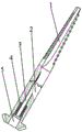
Fig. 1 is a schematic diagram of the overall structure of the preferred embodiment of the present invention.
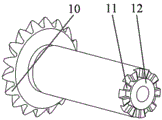
Fig. 2 is an isometric view of a spindle nose provided by the present invention.
Fig. 3 is an isometric view of a spindle bar according to the present invention.
Fig. 4 is a cross-sectional view of a spindle bar provided by the present invention.
Fig. 5 is a partial schematic view of the meshing state of the obstacle avoidance square teeth and the obstacle avoidance circular teeth provided by the invention.
Fig. 6 is a partial schematic view of the state of the obstacle avoidance square teeth and the obstacle avoidance circular teeth provided by the invention in a separated state.
In the figure, 1-ingot picking head, 2-ingot picking rod, 3-long bolt, 4-obstacle avoidance spring, 5-sealing screw, 6-hook tooth, 7-positioning hole, 8-threaded hole, 9-obstacle avoidance circular tooth, 10-bevel gear, 11-obstacle avoidance square tooth, 12-positioning boss, 13-sealing screw hole, 14-obstacle avoidance spring hole and 15-long bolt hole.
Detailed Description
Before any embodiments are explained in detail, it is to be understood that the disclosure is not limited in its application to the details of construction and the arrangement of components set forth in the following description or illustrated in the following drawings. The disclosure is capable of other embodiments and of being practiced or of being carried out in various ways.
Examples
Referring to fig. 1, the embodiment is a preferred embodiment of the present invention, and provides a cotton picker spindle capable of avoiding obstacles, which includes a spindle head 1, a spindle rod 2, a long bolt 3, an obstacle avoiding spring 4, and a seal screw 5. As shown in fig. 2, the outer surface of the upper end of the spindle head is provided with 3 rows of hook teeth 6, each row of hook teeth is 10 to 12, when the spindle rotates at a high speed, the hook teeth 6 advance spirally to pierce cotton fibers and further wind cotton, the picking process of the cotton is realized, and inclined grooves are formed between the hook teeth and used for cotton stripping. The lower end of the spindle picking head is provided with a positioning hole 7, a threaded hole 8 and an obstacle avoidance circular tooth 9, the edge of one side of the obstacle avoidance circular tooth 9 is provided with a fillet, and the diameter of the fillet is 5-8 mm, so that the spindle picking head and the spindle picking rod can slide. As shown in fig. 3, the upper end of the spindle rod is provided with a positioning boss 12 and obstacle avoidance square teeth 11, edges on two sides of the surface of the obstacle avoidance square teeth are provided with fillets, and the diameter of each fillet is not more than 1 mm, so that slippage between an obstacle avoidance square tooth head and an obstacle avoidance circular tooth is realized; the ingot picking rod 2 is internally provided with a sealing screw hole 13, an obstacle avoidance spring hole 14 and a long bolt hole 15, an obstacle avoidance square tooth 11 is meshed with an obstacle avoidance circular tooth 9, a positioning boss 12 is connected with a positioning hole 7, the two parts are both conical, and the taper range is 2-5 degrees; the sealing screw 5 is installed in sealing screw hole 13 department, keeps away barrier spring 4 and installs in keeping away barrier spring hole 15 department, the stay bolt 3 passes and keeps away barrier spring 4, stay bolt hole 15 and is connected with the screw hole 8 of spindle head lower extreme, the terminal surface is 6 millimeters to 9 millimeters under the stay bolt 3 head from sealing screw hole 13 lower terminal surface, guarantees to keep away effective compression of barrier spring to realize keeping away the barrier.
As shown in fig. 5, the ingot obstacle-avoiding square teeth 11 and the obstacle-avoiding circular teeth 9 are in a meshed state, when the hook teeth 6 on the outer surface of the ingot head 1 meet hard objects such as cotton stalks, bell shells and the like and are clamped, the obstacle-avoiding square teeth 11 on the upper end of the ingot rod 2 are disengaged and slide with the obstacle-avoiding circular teeth 9, and the ingot head 1 is pulled away from the ingot rod 2, which is shown in fig. 6. When the obstacle avoidance square teeth 11 and the obstacle avoidance circular teeth 9 shown in fig. 6 are in a separated state, the long bolt 3 moves outwards along with the spindle picking head 1, the obstacle avoidance spring 4 is compressed until the obstacle avoidance square teeth 11 and the obstacle avoidance circular teeth 9 are completely separated from a meshed state, the spindle picking rod 2 continues to rotate under the action of external driving force, and when the obstacle avoidance square teeth enter the next tooth groove, the spindle picking rod 1 returns under the action of the obstacle avoidance spring 4, and the obstacle avoidance process is completed.
As shown in figure 1, the outer surface of the ingot picking head 1 is covered with metal compounds (TiC, TiN, Al) with high hardness and high wear resistance2O3) Wherein the metallic compound coating has a thickness of 2 microns to 6 microns, which improves wear resistance of the spindle hook teeth, which in turn improves the service life of the spindle.
While the preferred embodiments of the invention have been disclosed for the purpose of illustration, it is not intended to be exhaustive or to limit the invention to any precise form or mode disclosed, and it will be understood by those skilled in the art that various changes may be made and equivalents may be substituted without departing from the scope of the invention, which is defined by the appended claims and all equivalents thereof.