[ summary of the invention ]
The invention aims to overcome the defects of the prior art and provide a garden tool with a longer service life of a motor.
The technical scheme adopted by the invention is as follows:
a garden tool comprises a brake device, an output shaft and a casing, wherein the brake device comprises a cutter holder, a driving shaft, a spring, a brake assembly, a friction plate and a shifting fork, the output shaft is rotatably arranged on the casing and is locked with the driving shaft so that the output shaft drives the driving shaft to rotate, the cutter holder is fixedly connected with the driving shaft, the shifting fork is rotatably arranged on the driving shaft, the friction plate is fixed on the casing, the cutter holder, the friction plate and the shifting fork are relatively fixed in the axial direction of the driving shaft, the brake assembly is movably arranged between the cutter holder and the shifting fork in the axial direction of the driving shaft, a top block is arranged on the shifting fork, the brake assembly comprises a slope-shaped piece and a brake piece arranged on the slope-shaped piece, one surface of the slope-shaped piece facing the shifting fork is a slope surface, the top block is abutted against, the other end of the brake component is extruded on the brake component, the brake component moves in the axial direction of the driving shaft to control the contact state between the braking surface on the brake component and the friction plate, the brake component is positioned on the driving shaft along the circumferential direction of the driving shaft, and when the braking surface is jointed with the friction plate, the brake component brakes the driving shaft.
The invention has the beneficial effects that:
the driving shaft is matched with the machine shell to limit the relative positions of the tool apron, the friction plate and the shifting fork, the shifting fork is extruded on the slope-shaped part in the rotating process to drive the slope-shaped part and the braking part connected with the slope-shaped part to move towards the tool apron together, the spring generates acting force towards the shifting fork on the braking assembly through deformation, and the ejector block and the spring respectively apply acting force to the braking assembly along two sides in the axial direction of the driving shaft so as to adjust the relative position of the braking assembly between the axial direction of the driving shaft and the friction plate. When the braking surface is attached to the friction plate, the friction force of the friction plate on the braking surface can prevent the braking part from rotating, and the braking part rotates synchronously with the driving shaft in the circumferential direction of the driving shaft, so that the friction plate can prevent the driving shaft from rotating, further prevent the working head connected with the driving shaft from rotating, and at the moment, the driving shaft cannot continue to work even if the motor is still in an open state, so that the motor does not need to be switched on and off frequently even if a worker leaves.
According to the invention, the driving shaft penetrates through the braking part, one of the braking part and the tool apron is provided with the first guide rail arranged along the axial direction of the driving shaft, the other one of the braking part and the tool apron is provided with the first guide block, the first guide block is connected in the first guide rail in a sliding mode, and the end part of the spring is extruded on the braking part.
The brake device also comprises a bottom shell and a pressing sheet, wherein the bottom shell is fixed on the shell, a supporting platform matched with the friction sheet in shape is formed by protruding the inner wall of the bottom shell, the friction sheet is assembled on the supporting platform, and the pressing sheet fixes the friction sheet on the supporting platform.
The inner wall of the bottom shell is protruded to form a plurality of convex ribs, clamping grooves are formed among the convex ribs, clamping blocks are arranged on the outer wall of the slope-shaped part, the driving shaft penetrates through the middle of the bottom shell and penetrates through the slope-shaped part, and the clamping blocks are located in the clamping grooves to circumferentially position the slope-shaped part in the bottom shell along the driving shaft.
The brake assembly further comprises a transition cover, the slope-shaped piece and the brake piece are annular, the driving shaft penetrates through center holes of the slope-shaped piece and the brake piece, the slope-shaped piece covers the transition cover, the transition cover is pressed on the brake piece, the end part of the spring is pressed on the transition cover, and the brake piece is located between the tool apron and the friction plate in the axial direction of the driving shaft.
One of the driving shaft and the transition cover is provided with a second guide rail arranged along the axial direction of the driving shaft, and the other one of the driving shaft and the transition cover is provided with a second guide block which is connected in the second guide rail in a sliding way.
The brake device also comprises a working head, the end part of the driving shaft is fixed on the working head to drive the working head to rotate, the tool apron is fixed on the working head, the end part of the driving shaft connected with the working head is positioned in the middle of the tool apron, and the driving shaft is fixed with the tool apron through the working head.
The edge of the shifting fork is protruded outwards to form a tongue-shaped hook, a rotary groove is formed in the side wall of the bottom shell, and the tongue-shaped hook is rotatably arranged at the rotary groove.
The tongue-shaped hook is provided with two gear holes, the hook is arranged in the shell, and the hook is hooked at one gear hole so as to position the tongue-shaped hook in the shell.
The middle of the driving shaft is provided with a mounting hole, the inner wall of the mounting hole is provided with a key groove, an output shaft is inserted in the mounting hole, a locking key is arranged in the key groove, and the locking key tightly clamps the output shaft at the mounting hole.
Other features and advantages of the present invention will be disclosed in more detail in the following detailed description of the invention and the accompanying drawings.
Example (b):
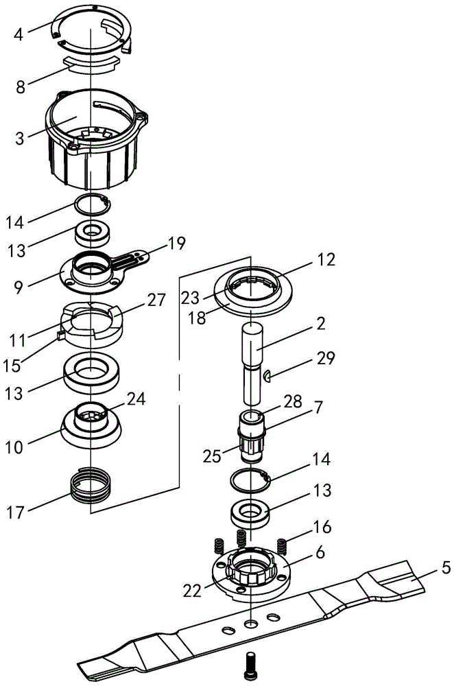
referring to fig. 1 to 9, the present embodiment provides a garden tool, which is embodied as a lawn mower in the present embodiment, including a brake actuating device, an output shaft 2 and a housing 1. The brake braking device comprises a bottom shell 3, a pressing sheet 4, a working head 5, a tool apron 6, a driving shaft 7, a spring, a braking assembly, a friction plate 8 and a shifting fork 9.
The shell 1 is provided with a motor, and the output shaft 2 is connected with a motor shaft, so that the output shaft 2 is rotatably arranged on the shell 1. The middle of the upper end face of the driving shaft 7 is provided with a mounting hole, the lower end of the output shaft 2 is inserted into the mounting hole, and the output shaft 2 is locked with the driving shaft 7, so that the output shaft 2 drives the driving shaft 7 to rotate. The lower end of the driving shaft 7 is fixed in the middle of the working head 5 through a fastening bolt so as to drive the working head 5 to rotate around the driving shaft 7 to perform cutting operation.
In order to ensure the locking effect of the output shaft 2 and the driving shaft 7 and avoid the relative movement of the output shaft 2 and the driving shaft 7 in the axial direction and the circumferential direction, the key groove 28 is arranged on the inner wall of the mounting hole, the locking key 29 is arranged in the key groove 28, and the locking key 29 clamps the lower end of the output shaft 2 in the mounting hole through deformation so as to ensure the connection strength between the output shaft 2 and the driving shaft 7.
The upper end of the key groove 28 also penetrates to the upper end surface of the drive shaft 7, thereby facilitating the installation of the lock key 29.
The bottom shell 3 in this embodiment is substantially cylindrical in shape, and the axis of the output shaft 2 substantially coincides with the axis of the bottom shell 3. The inner wall of the bottom shell 3 protrudes along the radial direction of the bottom shell 3 to form a supporting platform matched with the shape of the friction plate 8, so that the friction plate 8 is assembled on the supporting platform, and the supporting platform supports the friction plate 8 from bottom to top along the axial direction of the bottom shell 3. The pressing sheet 4 is pressed on the friction sheet 8 from top to bottom along the axial direction of the bottom shell 3 and is fixed with the support platform through screws, so that the friction sheet 8 is fixed on the support platform.
Since the bottom shell 3 is fixed to the housing 1 and the drive shaft 7 and the output shaft 2 are fixed in position relative to the housing 1 in the axial direction due to the manner in which the motor is assembled, the bottom shell 3 and the drive shaft 7 are fixed in position relative to each other in the axial direction of the drive shaft 7, and the friction plate 8 fixed to the bottom shell 3 and the drive shaft 7 are fixed in position relative to each other in the axial direction of the drive shaft 7.
In the embodiment, the support platform and the pressing sheet 4 are both circular, the friction plate 8 is approximately circular-arc-shaped, the drive shaft 7 and the output shaft 2 penetrate through the middle of the support platform and the pressing sheet 4, and the hole in the center of the support platform and the pressing sheet 4 avoids the drive shaft 7 and the output shaft 2.
The tool apron 6 is fixed on the working head 5 through a screw, a hole is formed in the center of the tool apron 6, the lower end of the driving shaft 7 is located in the hole in the center of the tool apron 6, the driving shaft 7 is fixed with the tool apron 6 through the working head 5, the driving shaft 7 drives the tool apron 6 to synchronously rotate, and meanwhile the tool apron 6 is fixed at the relative position between the driving shaft 7 and the driving shaft 7 in the axial direction of the driving shaft 7.
The driving shaft 7 penetrates through the center of the shifting fork 9, two clamping springs 14 are arranged on the driving shaft 7, and the shifting fork 9 is located between the two clamping springs 14, so that the shifting fork 9 is axially positioned on the driving shaft 7 along the driving shaft 7. Furthermore, a bearing 13 is arranged between the fork 9 and the drive shaft 7, the bearing 13 likewise being located between the two clamping springs 14. The fork 9 is rotatably arranged on the drive shaft 7 by means of a bearing 13.
Based on the above structure, the friction plate 8, the tool rest 6, and the shift fork 9 are fixed in position relative to each other in the axial direction of the drive shaft 7.
The driving shaft 7 also penetrates through a brake assembly, the brake assembly is movably arranged between the tool apron 6 and the shifting fork 9 in the axial direction of the driving shaft 7, and the brake assembly is matched with the friction plate 8 so as to brake the rotation of the driving shaft 7 under the condition that the motor is not stopped.
Specifically, the braking assembly includes a transition cover 10, a ramp 11, and a braking member 12 mounted on the ramp 11. The slope piece 11 and the braking piece 12 are both annular, a hole is arranged in the middle of the transition cover 10, and the driving shaft 7 penetrates through the centers of the slope piece 11, the transition cover 10 and the braking piece 12. The shifting fork 9, the slope piece 11, the transition cover 10, the braking piece 12 and the tool apron 6 are arranged in sequence along the axial direction of the driving shaft 7.
The ramp 11 is placed on the transition cover 10, and the transition cover 10 is pressed against the stop 12, so that the movement of the ramp 11, the transition cover 10 and the stop 12 in the axial direction of the drive shaft 7 is synchronized in unison.
The edge of the central hole of the tool apron 6 protrudes towards the braking piece 12 along the axial direction of the driving shaft 7 to form a first boss, a first guide rail 22 is arranged on the outer wall of the first boss along the axial direction of the driving shaft 7, the edge of the central hole of the braking piece 12 extends towards the tool apron 6 along the axial direction of the driving shaft 7 to form a first guide ring, a first guide block 23 is arranged on the inner wall of the first guide ring along the axial direction of the driving shaft 7, and the first guide block 23 is in sliding connection with the first guide rail 22. During the sliding of the first guide block 23 in the first guide rail 22, the stopper 12 can move in the axial direction of the driving shaft 7 relative to the holder 6 while limiting the relative rotation between the holder 6 and the stopper 12, so that the holder 6 and the stopper 12 can rotate synchronously.
The outer wall of the driving shaft 7 is provided with a second guide rail 25, the edge of the central hole of the transition cover 10 extends towards the tool apron 6 along the axial direction of the driving shaft 7 to form a second boss, the inner wall of the second boss is provided with a second guide block 24 along the axial direction of the driving shaft 7, and the second guide block 24 is connected in the second guide rail 25 in a sliding mode. During the sliding of the second guide block 24 in the second guide track 25, the transition cover 10 can translate in the axial direction of the drive shaft 7 relative to the drive shaft 7, but the transition cover 10 cannot rotate relative to the drive shaft 7, so that the transition cover 10 and the drive shaft 7 rotate synchronously.
Since the holder 6 and the driving shaft 7 rotate synchronously, the holder 6, the stopper 12 and the transition cover 10 all rotate synchronously when the driving shaft 7 rotates.
The inner wall protrusion of drain pan 3 forms a plurality of protruding muscle, forms the draw-in groove between the protruding muscle, is provided with fixture block 15 on the outer wall of sloping shape piece 11, and fixture block 15 is located in the draw-in groove in order to fix a position sloping shape piece 11 in drain pan 3 along drive shaft 7 circumference, and sloping shape piece 11 can be along drive shaft 7 axial displacement in the centre of drain pan 3 simultaneously. Therefore, the ramp 11 does not rotate when the driving shaft 7 rotates, so that the relative rotation between the ramp 11 and the transition cover 10 occurs, and for this reason, the bearing 13 is provided between the transition cover 10 and the ramp 11 to reduce the resistance of the relative rotation between the ramp 11 and the transition cover 10.
The transition cover 10 also prevents the ramp 11 from directly contacting the braking member 12, and prevents the braking member 12 from directly rubbing against the ramp 11 during relative rotation, thereby increasing the service life of the ramp 11 and the braking member 12.
In the present embodiment, the springs are divided into a first spring 16 and a second spring 17.
The first spring 16 has a lower end supported on the holder 6 and the other end pressed against the lower bottom surface of the stopper 12, and the first spring 16 presses the stopper 12 axially along the driving shaft 7 toward the fork 9, pressing the stopper 12 against the transition cover 10. Meanwhile, when the tool holder 6 and the braking member 12 rotate together, the first spring 16 is driven to rotate synchronously.
The lower end of the second spring 17 presses against the upper end wall of the first boss, the upper end of the second spring 17 presses against the lower bottom surface of the transition cover 10, and the second spring 17 presses the transition cover 10 axially along the drive shaft 7 towards the shift fork 9, pressing the transition cover 10 against the ramp 11. At the same time, when the holder 6 and the transition cover 10 rotate together, the second spring 17 rotates together about the drive shaft 7.
A hemispherical top block 26 is arranged on the bottom surface of the shifting fork 9, namely one surface of the shifting fork 9 facing the slope piece 11, a slope surface 27 is arranged on one surface of the slope piece 11 facing the shifting fork 9, the height of the slope surface 27 in the axial direction of the driving shaft 7 gradually increases or decreases, and the top block 26 is abutted against the slope surface 27. Due to the pressing action of the first spring 16 and the second spring 17, the top piece 26 exerts a pressing force on the ramp surface 27, which presses the tool holder 6 axially along the drive shaft 7.
Through the compression of the top block 26 and the cooperation of the second spring 17 and the first spring 16, the ramp 11, the transition cover 10 and the brake 12 can move synchronously and uniformly in the axial direction of the drive shaft 7.
During the rotation of the driving shaft 7 in the middle of the bottom shell 3, the ramp 11 does not rotate, the fork 9 can rotate freely with respect to the driving shaft 7, and the fork 9 cannot move axially on the driving shaft 7, but the ramp 11 can move axially on the driving shaft 7 by pressing the first spring 16 and the second spring 17.
Specifically, during the rotation of the fork 9 around the axis of the driving shaft 7, the top block 26 and the ramp surface 27 are in contact at different heights, and since the fork 9 cannot translate on the driving shaft 7, the ramp 11 can move towards the seat 6 by pressing the second spring 17 and the first spring 16 when the top block 26 gradually moves towards a higher position on the ramp surface 27, and the second spring 17 and the first spring 16 can press the ramp 11 towards the fork 9 when the top block 26 gradually moves towards a lower position on the ramp surface 27. The rotation of the fork 9 thus enables the synchronous movement of the ramp 11 and of the braking member 12 in the axial direction of the drive shaft 7 to be regulated, and consequently the position of the braking member 12 between the fork 9 and the seat 6, so as to vary the relative position between the braking member 12 and the friction plate 8.
In this embodiment, the upper surface of the braking member 12 is a braking surface 18, the braking surface 18 is located below the friction plate 8, the braking surface 18 is opposite to the friction plate 8 along the axial direction of the driving shaft 7, the braking member 12 can be limited upwards through the friction plate 8, and the braking member 12 is limited downwards through the tool apron 6. Movement of the braking member 12 in the axial direction of the drive shaft 7 controls the engagement or disengagement of the braking surface 18 with the friction plate 8.
When the motor rotates, if the braking surface 18 is engaged with the friction plate 8, the braking member 12 is gradually stopped due to friction, and the driving shaft 7 rotating synchronously with the braking member 12 is also stopped. If, on the other hand, the braking surface 18 and the friction lining 8 are separated, the braking element 12 and the drive shaft 7 can rotate again. The rotation state of the driving shaft 7 is adjusted by the shift fork 9 without frequently switching the motor on and off, so that the service life of the motor can be prolonged.
In order to control the shifting fork 9, the edge of the shifting fork 9 protrudes outward to form a tongue-shaped hook 19, a rotating groove 21 is formed on the side wall of the bottom shell 3, and the tongue-shaped hook 19 is rotatably arranged at the rotating groove 21. The shifting fork 9 is controlled through the tongue-shaped hook 19, the brake assembly is limited in the bottom shell 3, the sealing performance and the safety are improved, and the rotating groove 21 limits the rotating angle of the shifting fork 9.
Two gear holes 20 are formed in the tongue-shaped hook 19, a hook is arranged in the machine shell 1, different gear holes 20 are hooked through the hook, the rotating angle of the tongue-shaped hook 19 on the machine shell 3 is locked, and therefore the position of the tongue-shaped hook 19 in the machine shell 3 is located. When the hook hooks one gear hole 20, the friction plate 8 is separated from the braking surface 18, the driving shaft 7 can rotate freely to achieve a non-braking state, when the hook hooks the other gear hole 20, the friction plate 8 is attached to the braking surface 18, and the driving shaft 7 stops rotating to achieve a braking state.
While the invention has been described with reference to specific embodiments thereof, it will be understood by those skilled in the art that the invention is not limited thereto, and may be embodied in many different forms without departing from the spirit and scope of the invention as set forth in the following claims. Any modification which does not depart from the functional and structural principles of the present invention is intended to be included within the scope of the claims.