CN111010077A - Solar frame connecting structure and production method thereof - Google Patents
Solar frame connecting structure and production method thereof Download PDFInfo
- Publication number
- CN111010077A CN111010077A CN201911183880.XA CN201911183880A CN111010077A CN 111010077 A CN111010077 A CN 111010077A CN 201911183880 A CN201911183880 A CN 201911183880A CN 111010077 A CN111010077 A CN 111010077A
- Authority
- CN
- China
- Prior art keywords
- frame
- frames
- connection structure
- solar
- corner
- Prior art date
- Legal status (The legal status is an assumption and is not a legal conclusion. Google has not performed a legal analysis and makes no representation as to the accuracy of the status listed.)
- Pending
Links
Images


Classifications
-
- H—ELECTRICITY
- H02—GENERATION; CONVERSION OR DISTRIBUTION OF ELECTRIC POWER
- H02S—GENERATION OF ELECTRIC POWER BY CONVERSION OF INFRARED RADIATION, VISIBLE LIGHT OR ULTRAVIOLET LIGHT, e.g. USING PHOTOVOLTAIC [PV] MODULES
- H02S30/00—Structural details of PV modules other than those related to light conversion
- H02S30/10—Frame structures
-
- Y—GENERAL TAGGING OF NEW TECHNOLOGICAL DEVELOPMENTS; GENERAL TAGGING OF CROSS-SECTIONAL TECHNOLOGIES SPANNING OVER SEVERAL SECTIONS OF THE IPC; TECHNICAL SUBJECTS COVERED BY FORMER USPC CROSS-REFERENCE ART COLLECTIONS [XRACs] AND DIGESTS
- Y02—TECHNOLOGIES OR APPLICATIONS FOR MITIGATION OR ADAPTATION AGAINST CLIMATE CHANGE
- Y02E—REDUCTION OF GREENHOUSE GAS [GHG] EMISSIONS, RELATED TO ENERGY GENERATION, TRANSMISSION OR DISTRIBUTION
- Y02E10/00—Energy generation through renewable energy sources
- Y02E10/50—Photovoltaic [PV] energy
Landscapes
- Photovoltaic Devices (AREA)
Abstract
The invention relates to a solar frame connecting structure and a production method thereof, wherein the solar frame connecting structure produced by the method at least comprises a frame structure formed by splicing a pair of short frames and a pair of long frames, the short frames and the long frames are formed by continuously bending plate bodies into frame members provided with a first open slot and a second open slot, the slot bottom surfaces of the second open slots of the short frames and the long frames are provided with a plurality of riveting points, corner codes are arranged at the butt joint parts of the short frames and the long frames of adjacent sides, two ends of the corner codes are respectively matched with the second open slots in the short frames and the long frames of the adjacent sides, and the outer side surfaces of the corner codes are also clamped with the frames through corner code protection plates. The oblique notches are arranged at the frame, so that the frame can be ensured to be smooth and not to be dislocated when being spliced, and the frame can be prevented from being scrapped by the oblique notches, so that the frame can be recycled, and the scrapping risk is reduced.
Description
Technical Field
The invention relates to the field of solar frames, in particular to a solar frame connecting structure and a production method thereof.
Background
At present, traditional aluminium system solar energy frame is after assembling the panel finished product, if discovery leaks processing mounting hole or the hole that falls into water, then the monoblock panel is scrapped for the frame can not reuse, has improved the disability rate greatly, has seriously influenced the production efficiency of enterprise. In addition, most of the traditional solar frame materials are made of aluminum materials, the price of the traditional solar frame materials is higher than that of common industrial aluminum profiles, and the aluminum materials are poor in forming interaction, large in difficulty and high in cost.
Disclosure of Invention
The applicant carries out research and improvement aiming at the existing problems and provides a solar frame connecting structure and a production method thereof, which can avoid the problem that the frame is scrapped in the past, so that the frame can be repeatedly utilized, and the production efficiency of enterprises is greatly improved.
The technical scheme adopted by the invention is as follows:
the production method of the solar frame connecting structure comprises the following steps:
the first step is as follows: rolling: selecting a proper material belt, and then rolling the material belt into a working procedure piece by adopting a rolling line matched with a plurality of rollers;
the second step is that: stamping: utilizing a punch press to erect a stamping die to punch a riveting point and an assembling hole of each frame end on a process piece;
the third step: the solar frame is sawed and separated by automatic sawing equipment to form two short frames and two long frames.
The fourth step: two short frames and two long frames are assembled to form the solar frame connecting structure through the corner connectors and the corner connector guard plates.
Solar energy frame connection structure constitutes frame construction by a pair of short frame and a pair of long frame concatenation at least, short frame and long frame are buckled the frame spare that forms to set up first open slot and second open slot by the plate body in succession, set up a plurality of riveting points at the tank bottom surface of the second open slot of each short frame and long frame, and the angle sign indicating number sets up in the butt joint department of adjacent limit short frame and long frame, the both ends of angle sign indicating number cooperate with the second open slot in adjacent each short frame and the long frame respectively each lateral surface of angle sign indicating number still passes through angle sign indicating number backplate and each frame joint.
The further technical scheme is as follows:
the opening directions of the first open slot and the second open slot are opposite to each other;
one end of each short frame and one end of each long frame, which are butted with each other, are provided with inclined notches;
and a plurality of assembling holes for assembling the corner brace guard plate are formed in the bottom surface of the second opening groove of the frame.
The assembling hole is a square hole;
the angle brace is of an integrated structure formed by butting two plate bodies, and the inner side of each plate body is provided with an anti-falling tooth socket for riveting with a riveting point;
the angle brace guard plate is of an integrated structure formed by connecting a first plate body and second plate bodies connected to two ends of the first plate body, and one end, parallel to the inner side face of the first plate body, of each second plate body extends outwards to form a pair of assembling bosses;
the length of each assembling boss is matched with the assembling hole.
The invention has the following beneficial effects:
the Zn-Mg-Al ternary alloy coating steel plate is adopted to replace the original aluminum material, so that the corrosion resistance is excellent, various climatic conditions can be met, the processing performance is good, and the purchase cost of the material is greatly saved.
The frame splicing device is simple in structure and convenient to use, and the bevels are arranged at the frame positions to ensure that the frame is smooth and not misplaced during splicing.
Compared with the traditional aluminum frame formed by aluminum extrusion, the processing and forming method of the invention selects the Zn-Mg-Al ternary alloy coating steel plate to roll and form, improves the production efficiency, saves materials, and has high product strength and stable quality.
Drawings
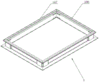
FIG. 1 is a schematic structural diagram of the present invention.
Fig. 2 is a schematic structural diagram of the present invention.
Fig. 3 is a schematic structural diagram of a solar energy frame according to the present invention.
Fig. 4 is an enlarged schematic view of fig. 3 at a.
FIG. 5 is a schematic structural diagram of the corner brace of the present invention.
FIG. 6 is a schematic view of the corner brace of the present invention.
FIG. 7 is a schematic cross-sectional view of the bezel of the present invention.
Wherein: 1. a frame structure; 101. a first open slot; 102. a second open slot; 103. riveting points; 104. an assembly hole; 105. a bevel notch; 106. a short frame; 107. a long frame; 2. corner connectors; 201. an anti-drop tooth socket; 3. Corner brace guard plates; 301. a first plate body; 302. a second plate body; 303. and assembling the boss.
Detailed Description
The following describes specific embodiments of the present invention.
The production method of the solar frame connecting structure comprises the following steps: the method comprises the following steps:
the first step is as follows: rolling: after selecting a proper material belt, a rolling line with the shaft diameter of 50mm is matched with 16 rollers to roll into a working procedure piece, and the rolling line can roll out the working procedure piece with the diameter of 12 meters per minute.
The second step is that: stamping: riveting points and assembly holes of each frame end are punched on a process piece by erecting a punching die by using a 160-ton punching machine, wherein the number of the assembly holes 104 is 4, and the number of the riveting points 103 is also 4.
The third step: an automatic sawing device with a saw blade with the diameter of 400mm is used for sawing and separating the solar frame to form two short frames and two long frames.
The fourth step: two short frames and two long frames are assembled to form the solar frame connecting structure through the corner connectors and the corner connector guard plates.
As shown in fig. 1 to 6, the solar frame connection structure is formed by at least splicing a pair of short frames 106 and a pair of long frames 107 to form a frame structure, the short frames 106 and the long frames 107 are formed by continuously bending a plate body to form a frame member provided with a first open slot 101 and a second open slot 102, a plurality of riveting points 103 are arranged on the bottom surface of the second open slot 102 of each short frame 106 and each long frame 107, an angle code 2 is arranged at the butt joint of the adjacent short frames 106 and the adjacent long frames 107, two ends of the angle code 2 are respectively matched with the second open slots 102 in the adjacent short frames 106 and the adjacent long frames 107, and each outer side surface of the angle code 2 is further clamped with each frame 1 through an angle code guard plate 3. The opening directions of the first opening groove 101 and the second opening groove 102 are opposite to each other.
The end of each short frame 106 and the long frame 107 that is butted with each other is provided with a bevel notch 105. The beveling angle of the beveling 105 is 45 degrees, so that the two frames 1 can be spliced to form a 90-degree corner part when being butted, the beveling 105 is firmly attached when being butted, and the beveling has the advantages of no out-of-tolerance leveling burrs and no dislocation. The bottom surface of the second opening groove 102 of the frame 1 is also provided with a plurality of assembly holes 104 for assembling the corner brace guard plate 3, and the assembly holes 104 are square holes.
As shown in fig. 1 to 3, the corner brace 2 is formed in an integral structure by butting two plate bodies, and an anti-falling tooth groove 201 for riveting with a riveting point 103 is formed in each plate body. The angle brace 3 is formed by connecting a first plate 301 and second plates 302 connected to two ends of the first plate 301 to form an integrated structure, and one end of the second plate 302 parallel to the inner side of the first plate 301 extends outward to form a pair of assembling bosses 303. The length of each mounting boss 303 fits into the mounting hole 104.
The specific assembly process of the invention is as follows:
as shown in fig. 1 to 6, first, oblique notches of 45 ° are obliquely cut on the both ends of each of the short frame 106 and the long frame 107 on line by a rolling line, and then the assembly holes 104 and the riveting points 103 of the mounting corner gusset 3 are punched on line by the rolling line. Then, each fitting boss 303 of the corner brace 3 is fitted into the fitting hole 104 of the long rim 107 or the short rim 106, thereby fixing the corner brace 3. At this time, a gap for embedding the corner connectors 2 is formed between the inner side of the corner connector guard plate 3 and the inner side of the long frame 107 or the short frame 106, the corner connectors 2 are inserted into the gap in the short frame 106, and then the short frame 106 with the corner connectors 2 mounted thereon is assembled in the gap for mounting the corner connectors 2 in the long frame 107, wherein the short frame 106 and the long frame 107 are spliced to form the corner connector.
According to the invention, the short frame 106 and the long frame 107 are both made of Zn-Mg-Al ternary alloy coated steel plates, so that excellent corrosion resistance is ensured, various climatic conditions are met, and good processability is achieved, and the cost is greatly reduced from the material perspective. Meanwhile, the short frame 106 and the long frame 107 are formed by rolling, so that the production efficiency is improved, the material can be effectively saved, and the product has high strength and stable quality.
The frame splicing device is simple in structure and convenient to use, and the bevels are arranged at the frame positions to ensure that the frame is smooth and not misplaced during splicing.
The foregoing description is illustrative of the present invention and is not to be construed as limiting thereof, the scope of the invention being defined by the appended claims, which may be modified in any manner without departing from the basic structure thereof.
Claims (9)
Priority Applications (1)
| Application Number | Priority Date | Filing Date | Title |
|---|---|---|---|
| CN201911183880.XA CN111010077A (en) | 2019-11-27 | 2019-11-27 | Solar frame connecting structure and production method thereof |
Applications Claiming Priority (1)
| Application Number | Priority Date | Filing Date | Title |
|---|---|---|---|
| CN201911183880.XA CN111010077A (en) | 2019-11-27 | 2019-11-27 | Solar frame connecting structure and production method thereof |
Publications (1)
| Publication Number | Publication Date |
|---|---|
| CN111010077A true CN111010077A (en) | 2020-04-14 |
Family
ID=70112254
Family Applications (1)
| Application Number | Title | Priority Date | Filing Date |
|---|---|---|---|
| CN201911183880.XA Pending CN111010077A (en) | 2019-11-27 | 2019-11-27 | Solar frame connecting structure and production method thereof |
Country Status (1)
| Country | Link |
|---|---|
| CN (1) | CN111010077A (en) |
Citations (9)
| Publication number | Priority date | Publication date | Assignee | Title |
|---|---|---|---|---|
| CN202183388U (en) * | 2011-08-30 | 2012-04-04 | 常州天合光能有限公司 | Detachable aluminum frame of solar module |
| EP2477232A2 (en) * | 2011-01-05 | 2012-07-18 | BPE e. K. | Solar module |
| CN102668122A (en) * | 2009-12-18 | 2012-09-12 | 肖特太阳能控股公司 | Method for producing a frame and solar cell module frame |
| US20140238489A1 (en) * | 2013-02-28 | 2014-08-28 | Robert Bosch Gmbh | Frame for a Solar Module |
| CN205453615U (en) * | 2015-12-25 | 2016-08-10 | 保定光为绿色能源科技有限公司 | Angle bead for solar PV modules |
| CN208272919U (en) * | 2018-06-28 | 2018-12-21 | 天合光能股份有限公司 | Frame structure of a new type of photovoltaic cell assembly and photovoltaic cell assembly |
| CN208761268U (en) * | 2018-07-25 | 2019-04-19 | 广州欧派集成家居有限公司 | Corner protector and protection combination |
| CN109818560A (en) * | 2017-11-22 | 2019-05-28 | 浙江亿发新能源有限公司 | Photovoltaic module aluminum corner brace |
| CN210839456U (en) * | 2019-11-27 | 2020-06-23 | 无锡铸华机械科技有限公司 | Solar energy frame connection structure |
-
2019
- 2019-11-27 CN CN201911183880.XA patent/CN111010077A/en active Pending
Patent Citations (9)
| Publication number | Priority date | Publication date | Assignee | Title |
|---|---|---|---|---|
| CN102668122A (en) * | 2009-12-18 | 2012-09-12 | 肖特太阳能控股公司 | Method for producing a frame and solar cell module frame |
| EP2477232A2 (en) * | 2011-01-05 | 2012-07-18 | BPE e. K. | Solar module |
| CN202183388U (en) * | 2011-08-30 | 2012-04-04 | 常州天合光能有限公司 | Detachable aluminum frame of solar module |
| US20140238489A1 (en) * | 2013-02-28 | 2014-08-28 | Robert Bosch Gmbh | Frame for a Solar Module |
| CN205453615U (en) * | 2015-12-25 | 2016-08-10 | 保定光为绿色能源科技有限公司 | Angle bead for solar PV modules |
| CN109818560A (en) * | 2017-11-22 | 2019-05-28 | 浙江亿发新能源有限公司 | Photovoltaic module aluminum corner brace |
| CN208272919U (en) * | 2018-06-28 | 2018-12-21 | 天合光能股份有限公司 | Frame structure of a new type of photovoltaic cell assembly and photovoltaic cell assembly |
| CN208761268U (en) * | 2018-07-25 | 2019-04-19 | 广州欧派集成家居有限公司 | Corner protector and protection combination |
| CN210839456U (en) * | 2019-11-27 | 2020-06-23 | 无锡铸华机械科技有限公司 | Solar energy frame connection structure |
Similar Documents
| Publication | Publication Date | Title |
|---|---|---|
| KR101931320B1 (en) | Busbar for electric automobiles and method of manufacturing the same | |
| CN210839456U (en) | Solar energy frame connection structure | |
| CN111010077A (en) | Solar frame connecting structure and production method thereof | |
| CN108942117B (en) | U-shaped aluminum material L-shaped bevel machining process | |
| CN112325014B (en) | Air pipe assembling method and air pipe assembling structure based on cold-bending formed flange | |
| TWM636303U (en) | Steel combined structure | |
| CN222089506U (en) | Complete steel frame structure for solar module | |
| KR200455022Y1 (en) | Filter frame | |
| JP2015112643A (en) | Stacking die | |
| CN209896998U (en) | Solar photovoltaic module aluminium alloy frame | |
| CN112524361B (en) | Integrally formed flange based on cold bending process and machining method thereof | |
| CN210817453U (en) | Splicing type shell sheet metal part for casting machine | |
| CN110385379B (en) | A thick steel plate connection structure with high connection strength and easy assembly and disassembly and an assembly and disassembly method | |
| JP4536312B2 (en) | Manufacturing method of steel sheet for welding backing | |
| CN111576850B (en) | Aluminum alloy template, connection and clamping structure and connection method thereof | |
| JP2009511832A (en) | Core plate consisting of multiple members | |
| CN217617127U (en) | Spinning equipment for fan impeller | |
| CN223393076U (en) | Novel filter outer frame | |
| CN216156930U (en) | Light steel keel capable of being bent at will | |
| CN220488013U (en) | Novel sheet metal connecting piece | |
| CN217151546U (en) | Connecting structure of vertical rod and clamping plate | |
| CN210976556U (en) | A horizontal bar for scaffolding | |
| CN213655247U (en) | A connection structure of a centrifugal fan side plate and a worm plate | |
| CN215032482U (en) | Bending stamping part correcting tool | |
| CN217240647U (en) | Novel photovoltaic module roll forming frame and corner connector |
Legal Events
| Date | Code | Title | Description |
|---|---|---|---|
| PB01 | Publication | ||
| PB01 | Publication | ||
| SE01 | Entry into force of request for substantive examination | ||
| SE01 | Entry into force of request for substantive examination | ||
| RJ01 | Rejection of invention patent application after publication |
Application publication date: 20200414 |
|
| RJ01 | Rejection of invention patent application after publication |