Disclosure of Invention
Aiming at the technical defects, the invention provides a cleaning and disinfecting device for a gastroscope, which can overcome the defects.
The invention discloses a cleaning and disinfecting device for gastroscopes, which comprises an outer shell, wherein a cleaning box is arranged in the outer shell, a left drying box is arranged on the right side of the cleaning box, a disinfecting box is arranged on the right side of the left drying box, cleaning components are arranged in the cleaning box and the disinfecting box, a right drying box is arranged on the right side of the disinfecting box, drying components are arranged in the left drying box and the right drying box, an ultraviolet disinfecting box is arranged on the right side of the right drying box, an irradiation component is arranged in the ultraviolet disinfecting box, a storage box is arranged on the right side of the ultraviolet disinfecting box, and a storage component is arranged in the storage box;
a fan cavity is arranged below the cleaning box, a transmission cavity is arranged above the cleaning box, a placing box is arranged on the left side of the transmission cavity, a lower sliding cavity is arranged in the lower sliding cavity, a slope is arranged in the lower sliding cavity, the lower sliding cavity is communicated with the transmission cavity and is provided with a gastroscope, a magnet is adsorbed below the gastroscope, a left helical gear cavity is arranged above the transmission cavity, a right helical gear cavity is arranged on the right side of the left helical gear cavity, a transmission bevel gear cavity is arranged on the right side of the right bevel gear cavity, a driving motor is arranged in the lower end wall of the fan cavity, a lower fan shaft is connected above the driving motor in a power mode, a first belt pulley positioned in the fan cavity is fixedly installed on the lower fan shaft, the first belt pulley is fixedly arranged on the lower fan shaft, a second belt pulley is arranged on the left side of the first belt pulley, and the first belt pulley and the second belt pulley are connected by a rotating belt;
the second belt pulley fixed mounting is on the primary shaft, the primary shaft rotates to be installed the fan chamber in extend to the transmission intracavity between the transmission chamber, be equipped with the third belt pulley of fixed mounting on the primary shaft in the transmission intracavity, the third belt pulley right side is equipped with the fourth belt pulley, the third belt pulley is connected by drive belt with the fourth belt pulley, fourth belt pulley fixed mounting is on the secondary shaft, the secondary shaft rotates to be installed the transmission chamber with between the left side helical gear chamber.
Preferably, the cleaning component comprises a decontamination chamber positioned in the cleaning box and the disinfection box, a cleaning inner box is arranged in the decontamination chamber, a cleaning chamber is arranged in the cleaning inner box, an upper stirring fan is arranged in the cleaning chamber, the upper stirring fan is fixedly arranged on an upper fan shaft, the front end of the upper fan shaft is dynamically arranged on a fan motor positioned in the front end wall of the cleaning box, a downstream chamber is arranged below the cleaning chamber, a pressure one-way valve is arranged in the downstream chamber, an upper filter plate is fixedly arranged at the lower end of the downstream chamber, a cleaning connection chamber is arranged below the upper filter plate, a lower filter plate is fixedly arranged at the lower end of the cleaning connection chamber, the lower filter plate is communicated with the decontamination chamber, a lower stirring fan is arranged in the decontamination chamber, the lower stirring fan is fixedly arranged on a lower stirring shaft, and a third shaft is rotatably arranged on the left end face and the right end face of the, and a fifth gear is fixedly mounted on the third shaft.
Preferably, a sixth gear located in the transmission cavity is arranged above the fifth gear, the sixth gear is fixedly installed on a fourth shaft, the right end of the fourth shaft is rotatably installed in the right end wall of the transmission cavity, the sixth gear and the fifth gear are connected by a first magnetic chain, a first belt connecting part is arranged in the transmission cavity, the first belt connecting part comprises a front leather wheel, a rear belt pulley is arranged on the rear side of the front leather wheel, the rear belt pulley is connected with the front leather wheel by a belt, the rear belt pulley is fixedly installed on the fourth shaft, the front leather wheel is fixedly installed on the fifth shaft, the fifth shaft is rotatably installed in the transmission cavity and the left helical gear cavity, a seventh helical gear fixedly installed on the fifth shaft is arranged in the left helical gear cavity, and an eighth helical gear is engaged with the gear below the seventh helical gear, the eighth helical gear is fixedly arranged on the second shaft, the second shaft is rotatably arranged between the left helical gear cavity and the transmission cavity, a ninth gear fixedly arranged on the second shaft is arranged in the transmission cavity, a second belt connecting part fixedly arranged on the second shaft is arranged at the lower end of the ninth gear, the belt connecting part is also fixedly arranged on a seventh shaft rotatably arranged in the upper end wall of the transmission cavity, a tenth gear fixedly arranged on the first shaft is arranged in the transmission cavity, an eleventh gear is arranged on the right side of the tenth gear, the tenth gear is connected with the eleventh gear through a second magnetic chain, the eleventh gear is fixedly arranged on an eighth shaft, the eighth shaft is rotatably arranged between the transmission cavity and the right helical gear cavity, and a twelfth gear is arranged on the right side of the ninth gear, the ninth gear and the twelfth gear are connected by a third magnetic chain, the twelfth gear is fixedly mounted on a ninth shaft, the ninth shaft is rotatably mounted in the lower end wall of the transmission cavity, a third belt connecting part fixedly mounted on the eighth shaft is arranged above the eleventh gear, the third belt connecting part is also fixedly mounted on a tenth shaft, the tenth shaft is rotatably mounted between the right helical gear cavity and the transmission cavity, a thirteenth gear positioned in the transmission cavity is fixedly mounted on the tenth shaft, a fourteenth helical gear positioned in the right helical gear cavity and fixedly mounted on the tenth shaft is arranged above the thirteenth gear, a fifteenth helical gear is engaged and connected to the right side of the fourteenth helical gear, the fifteenth helical gear is fixedly mounted on the tenth shaft, and the eleventh shaft is rotatably mounted between the right helical gear cavity and the transmission cavity, the transmission cavity is internally provided with a fourth belt connecting part fixedly mounted on an eleventh shaft, the fourth belt connecting part is further fixedly mounted on a twelfth shaft, a sixteenth gear is arranged in the transmission cavity, and the sixteenth gear is fixedly mounted on the twelfth shaft.
Preferably, the drying assembly comprises a drying cavity located in the left drying box and the right drying box, a plurality of heating pipes are arranged in an end wall between the drying cavity and the left drying box, a thirteenth shaft is rotatably mounted in the left and right end walls of the drying cavity, a seventeenth gear is fixedly mounted on the thirteenth shaft, a drying fan is further arranged in the drying cavity, the drying fan is fixedly mounted on a tenth shaft, and a fifteenth shaft is rotatably mounted between the drying cavity and the fan cavity.
Preferably, the seventeenth gear with the sixteenth gear is connected by the fourth magnetism chain, the thirteenth gear right side is equipped with eighteenth gear, the thirteenth gear with the eighteenth gear is connected by the fifth magnetism chain, eighteenth gear fixed mounting is on the fourteenth shaft, the fourteenth shaft is rotated and is installed in the end wall in transmission chamber, still be equipped with fixed mounting in the fan intracavity the epaxial nineteenth gear of fifteenth, nineteenth gear right side gear meshing is connected with left drive gear, left drive gear right side gear meshing is connected with right drive gear, nineteenth gear left side gear meshing is connected with fixed mounting is in the epaxial twentieth gear of fan down.
Preferably, a twenty-first helical gear is fixedly mounted above the eighteenth gear on a fourteenth shaft, a twenty-second helical gear is meshed with a gear on the left side of the twenty-first helical gear, the twenty-second helical gear is fixedly mounted on a sixteenth shaft, the sixteenth shaft is rotatably mounted in the end wall of the transmission cavity, a fifth belt connecting part is arranged on the left side of the twenty-second helical gear, one belt pulley in the fifth belt connecting part is fixedly mounted on the sixteenth shaft, the other belt pulley in the fifth belt connecting part is fixedly mounted on a seventeenth shaft, the seventeenth shaft is rotatably mounted in the end wall of the transmission cavity, a twenty-third gear on the left side of the fifth belt connecting part is fixedly mounted on the seventeenth shaft, and the twenty-third gear is connected with a fifth gear in the disinfection box through a sixth magnetic chain, a sixth belt connecting part positioned below the twelfth gear is fixedly arranged on the ninth shaft, a belt pulley in the sixth belt connecting part is fixedly arranged on the ninth shaft, another belt pulley in the sixth belt connecting part is fixedly arranged on an eighteenth shaft, the eighteenth shaft is rotatably arranged in the end wall of the transmission cavity, a twenty-fourth gear positioned below the sixth belt connecting part is fixedly arranged on the eighteenth shaft, a twenty-fifth gear is arranged on the right side of the twenty-fourth gear, the twenty-fifth gear is fixedly arranged on a nineteenth shaft, the nineteenth shaft is rotatably arranged in the end wall of the transmission cavity, the twenty-fourth gear and the twenty-fifth gear are connected by a seventh magnetic chain, a seventh belt connecting part fixedly arranged on a fourteenth shaft is arranged below the eighteenth gear, and a belt pulley in the seventh belt connecting part is fixedly arranged on a fourteenth shaft, another belt pulley fixed mounting in the seventh belt coupling spare is on the twentieth shaft, the twentieth shaft rotates and installs in the end wall in transmission chamber, seventh belt coupling spare below is equipped with fixed mounting in the twenty-sixth epaxial gear of second, there is eighteen second gears on the twenty-sixth gear right side, twenty-seventh gear fixed mounting is on the twenty-first shaft, the twenty-first shaft rotates and installs transmission chamber with between the transmission helical gear chamber, twenty-seventh gear with the twenty-sixth gear is connected by eighth magnetism chain.
Preferably, twenty-eighth helical gear is arranged on the right side of the twenty-first helical gear in a meshed manner, the twenty-eighth helical gear is fixedly installed on a twenty-second shaft, the twenty-second shaft is rotatably installed in the end wall of the transmission cavity, an eighth belt connecting component is arranged on the right side of the twenty-eighth helical gear, a belt pulley in the eighth belt connecting component is fixedly installed on the twenty-second shaft, another belt pulley in the eighth belt connecting component is fixedly installed on a twenty-third shaft, the twenty-third shaft is rotatably installed in the end wall of the transmission cavity, the twenty-third shaft is fixedly installed with a twenty-ninth gear located on the right side of the eighth belt connecting component, and the twenty-ninth gear is connected with a seventeenth gear in the right drying box through a ninth magnetic chain.
Preferably, the irradiation assembly comprises an ultraviolet irradiation cavity located in the ultraviolet sterilization box, a twenty-fourth shaft is rotatably mounted on the left and right end walls of the ultraviolet irradiation cavity, a thirtieth gear is fixedly mounted on the twenty-fourth shaft, an ultraviolet irradiation device is arranged in the ultraviolet sterilization box and the ultraviolet irradiation cavity, a thirty-first helical gear fixedly mounted on the twenty-seventh gear is arranged above the twenty-seventh gear, a thirty-second helical gear is meshed with a left side gear of the thirty-first helical gear, the thirty-second helical gear is fixedly mounted on the twenty-fifth shaft, the twenty-fifth shaft is rotatably mounted in the end wall of the transmission cavity, a ninth belt connecting component is arranged on the left side of the thirty-second helical gear, a belt pulley in the ninth belt connecting component is fixedly mounted on the twenty-fifth shaft, and another belt pulley in the ninth belt connecting component is fixedly mounted on the twenty-sixth shaft, the twenty-sixth shaft is rotatably installed in the end wall of the transmission cavity, a thirty-third gear on the left side of the ninth belt connecting part is fixedly installed on the twenty-sixth shaft, the thirty-third gear is connected with the thirty gear through a tenth magnetic chain, a tenth belt connecting part fixedly installed on a nineteenth shaft is arranged below the twenty-fifth gear, a belt pulley in the tenth belt connecting part is fixedly installed on the nineteenth shaft, another belt pulley in the tenth belt connecting part is fixedly installed on a twenty-seventh shaft, the twenty-seventh shaft is rotatably installed in the end wall of the transmission cavity, a thirty-fourth gear on the twenty-seventh shaft is fixedly installed below the tenth belt connecting part, a thirty-fifth gear is arranged on the right side of the thirty-fourth gear, and the thirty-fourth gear is connected with the thirty-fifth gear through an eleventh magnetic chain, the thirty-fifth gear is fixedly arranged on a twenty-eighth shaft, and the twenty-eighth shaft is rotatably arranged in the end wall of the transmission cavity.
Preferably, the storage assembly comprises a storage cavity arranged in the storage box, a plurality of storage magnets are arranged on the end walls of the storage cavity, a twenty-ninth shaft is rotatably arranged on the left end wall and the right end wall of the storage cavity, a thirty-sixth gear is fixedly arranged on the twenty-ninth shaft, a thirty-seventh helical gear is arranged on the right side of the thirty-ninth helical gear in a meshed manner, the thirty-seventh helical gear is fixedly arranged on a twenty-fifth shaft, an eleventh belt connecting component is arranged on the right side of the thirty-seventh helical gear, a belt pulley in the eleventh belt connecting component is fixedly arranged on the twenty-fifth shaft, another belt pulley in the eleventh belt connecting component is fixedly arranged on the thirty shaft, the thirtieth shaft is rotatably arranged in the end wall of the transmission cavity, and a thirty-eighth gear on the right side of the eleventh belt connecting component is fixedly arranged on the thirty shaft, and the thirty-eighth gear and the thirty-sixth gear are connected by a twelfth magnetic chain.
Preferably, the magnetism of the second magnetic chain is smaller than that of the first magnetic chain, the magnetism of the first magnetic chain is smaller than that of the third magnetic chain, the magnetism of the third magnetic chain is smaller than that of the fourth magnetic chain, the magnetism of the fourth magnetic chain is smaller than that of the fifth magnetic chain, the magnetism of the fifth magnetic chain is smaller than that of the sixth magnetic chain, the magnetism of the sixth magnetic chain is smaller than that of the seventh magnetic chain, the magnetism of the seventh magnetic chain is smaller than that of the ninth magnetic chain, the magnetism of the ninth magnetic chain is smaller than that of the eighth magnetic chain, the magnetism of the eighth magnetic chain is smaller than that of the tenth magnetic chain, the magnetism of the tenth magnetic chain is smaller than that of the eleventh magnetic chain, and the magnetism of the eleventh magnetic chain is smaller than that of the twelfth magnetic chain, the twelfth magnetic chain is less magnetic than the storage magnet.
The beneficial effects are that: the washing of this device does not pass through washing sponge friction and uses rivers to flow rapidly and take away the spot on the gastroscope, it can get into stoving case stoving then gets into the disinfect box disinfection to wash, and disinfect box and washing case all are equipped with automatic purification sewage device, get into stoving case stoving once more after the disinfectant is accomplished, then get into the ultraviolet irradiation case and carry out the health that the secondary was disinfected and guarantee the gastroscope, get into storage box storage at last, all processes are whole automatic, the artificial pressure of hospital has been saved greatly, and high efficiency, the cleaning and disinfecting is effectual.
Detailed Description
All of the features disclosed in this specification, or all of the steps in any method or process so disclosed, may be combined in any combination, except combinations of features and/or steps that are mutually exclusive.
The invention will now be described in detail with reference to fig. 1-6, for convenience of description, the following orientations will now be defined: the up, down, left, right, and front-back directions described below correspond to the up, down, left, right, and front-back directions in the projection relationship of fig. 1 itself.
The invention relates to a cleaning and disinfecting device for gastroscope, which comprises an outer shell 81, wherein a cleaning box 59 is arranged in the outer shell 81, a left drying box 83 is arranged on the right side of the cleaning box 59, a disinfecting box 167 is arranged on the right side of the left drying box 83, cleaning components are respectively arranged in the cleaning box 59 and the disinfecting box 167, a right drying box 166 is arranged on the right side of the disinfecting box 167, drying components are respectively arranged in the left drying box 83 and the right drying box 166, an ultraviolet sterilizing box 48 is arranged on the right side of the right drying box 166, an irradiation component is arranged in the ultraviolet sterilizing box 48, a storage box 40 is arranged on the right side of the ultraviolet sterilizing box 48, a storage component is arranged in the storage box 40, a fan cavity 66 is arranged below the cleaning box 59, a transmission cavity 172 is arranged above the cleaning box 59, a storage box 87 is arranged on the left side of the transmission cavity 172, and a, a slope is arranged in the lower sliding cavity 88, the lower sliding cavity 88 is communicated with the transmission cavity 172 and is provided with a gastroscope 170, a magnet 174 is adsorbed below the gastroscope, a left helical gear cavity 175 is arranged above the transmission cavity 172, a right helical gear cavity 13 is arranged on the right side of the left helical gear cavity 175, a transmission helical gear cavity 164 is arranged on the right side of the right helical gear cavity 13, a driving motor 63 is arranged in the lower end wall of the fan cavity 66, a lower fan shaft 62 is connected above the driving motor 63 in a power mode, a first belt pulley 64 positioned in the fan cavity 66 is fixedly arranged on the lower fan shaft 62, a second belt pulley 67 is arranged on the left side of the first belt pulley 64, the first belt pulley 64 is connected with the second belt pulley 67 through a rotating belt 65, and the second belt pulley 67 is fixedly arranged on the first shaft 68, the first shaft 68 is rotatably installed between the fan cavity 66 and the transmission cavity 172 and extends into the transmission cavity 172, a third belt pulley 171 fixedly installed on the first shaft 68 is arranged in the transmission cavity 172, a fourth belt pulley 86 is arranged on the right side of the third belt pulley 171, the third belt pulley 171 and the fourth belt pulley 86 are connected by a transmission belt 1, the fourth belt pulley 86 is fixedly installed on the second shaft 92, and the second shaft 92 is rotatably installed between the transmission cavity 172 and the left bevel gear cavity 175.
Advantageously, the cleaning assembly comprises a decontamination chamber 75 located in the cleaning box 59 and the disinfection box 167, a cleaning inner box 76 is arranged in the decontamination chamber 75, a cleaning chamber 77 is arranged in the cleaning inner box 76, an upper stirring fan 180 is arranged in the cleaning chamber 77, the upper stirring fan 180 is fixedly mounted on an upper fan shaft 181, the front end of the upper fan shaft 181 is dynamically mounted on a fan motor 182 located in the front end wall of the cleaning box 59, a lower flow chamber 74 is arranged below the cleaning chamber 77, a pressure one-way valve 73 is arranged in the lower flow chamber 74, an upper filter plate 72 is fixedly mounted at the lower end of the lower flow chamber 74, a cleaning connection chamber 71 is arranged below the upper filter plate 72, a lower filter plate 69 is fixedly mounted at the lower end of the cleaning connection chamber 71, the lower filter plate 69 is communicated with the decontamination chamber 75, a lower stirring fan 61 is arranged in the decontamination chamber 75, the lower stirring fan 61 is fixedly mounted on the lower stirring shaft 62, the left end face and the right end face of the cleaning cavity 77 are rotatably provided with a third shaft 78, and a fifth gear 79 is fixedly arranged on the third shaft 78.
Advantageously, a sixth gear 100 is disposed above the fifth gear 79 and located in the transmission cavity 172, the sixth gear 100 is fixedly mounted on a fourth shaft 98, the right end of the fourth shaft 98 is rotatably mounted in the right end wall of the transmission cavity 172, the sixth gear 100 and the fifth gear 79 are connected by a first magnetic chain 80, a first belt connecting component 101 is disposed in the transmission cavity 172, the first belt connecting component 101 includes a front pulley 96, a rear pulley 97 is disposed at the rear side of the front pulley 96, the rear pulley 97 is connected with the front pulley 96 by a belt 99, the rear pulley 97 is fixedly mounted on the fourth shaft 98, the front pulley 96 is fixedly mounted on a fifth shaft 95, the fifth shaft 95 is rotatably mounted in the transmission cavity 172 and the left helical gear cavity 175, a seventh helical gear 94 is disposed in the left helical gear cavity 175 and fixedly mounted on the fifth shaft 95, an eighth bevel gear 93 is engaged with a gear below the seventh bevel gear 94, the eighth bevel gear 93 is fixedly mounted on a second shaft 92, the second shaft 92 is rotatably mounted between the left bevel gear cavity 175 and the transmission cavity 172, a ninth gear 4 fixedly mounted on the second shaft 92 is arranged in the transmission cavity 172, a second belt connecting part 3 fixedly mounted on the second shaft 92 is arranged at the lower end of the ninth gear 4, the belt connecting part 3 is further fixedly mounted on a seventh shaft 5 rotatably mounted in the upper end wall of the transmission cavity 172, a tenth gear 173 fixedly mounted on the first shaft 68 is arranged in the transmission cavity 172, an eleventh gear 6 is arranged on the right side of the tenth gear 173, the tenth gear 173 is connected with the eleventh gear 6 through a second magnetic chain 2, and the eleventh gear 6 is fixedly mounted on an eighth shaft 7, the eighth shaft 7 is rotatably installed between the transmission cavity 172 and the right helical gear cavity 13, the right side of the ninth gear 4 is provided with a twelfth gear 127, the ninth gear 4 is connected with the twelfth gear 127 by a third magnetic chain 128, the twelfth gear 127 is fixedly installed on a ninth shaft 126, the ninth shaft 126 is rotatably installed in the lower end wall of the transmission cavity 172, a third belt connecting part 10 fixedly installed on the eighth shaft 7 is arranged above the eleventh gear 6, the third belt connecting part 10 is further fixedly installed on a tenth shaft 11, the tenth shaft 11 is rotatably installed between the right helical gear cavity 13 and the transmission cavity 172, a thirteenth gear 16 located in the transmission cavity 172 is fixedly installed on the tenth shaft 11, a fourteenth helical gear 12 located in the right helical gear cavity 13 and fixedly installed on the tenth shaft 11 is arranged above the thirteenth gear 16, a fifteenth helical gear 14 is engaged and connected to a right side gear of the fourteenth helical gear 12, the fifteenth helical gear 14 is fixedly mounted on an eleventh shaft 15, the eleventh shaft 15 is rotatably mounted between the right helical gear cavity 13 and the transmission cavity 172, a fourth belt connecting component 134 fixedly mounted on the tenth shaft 15 is disposed in the transmission cavity 172, the fourth belt connecting component 134 is further fixedly mounted on a twelfth shaft 139, a sixteenth gear 137 is disposed in the transmission cavity 172, and the sixteenth gear 137 is fixedly mounted on the twelfth shaft 139.
Advantageously, the drying assembly includes a drying chamber 53 located in the left drying box 83 and the right drying box 116, a plurality of heating pipes 84 are disposed in an end wall between the drying chamber 53 and the left drying box 83, a thirteenth shaft 51 is rotatably mounted on left and right end walls of the drying chamber 53, a seventeenth gear 52 is fixedly mounted on the thirteenth shaft 51, a drying fan 54 is further disposed in the drying chamber 53, the drying fan 54 is fixedly mounted on a twelfth shaft 56, and the fifteenth shaft 56 is rotatably mounted between the drying chamber 53 and the fan chamber 66.
Beneficially, the seventeenth gear 52 and the sixteenth gear 137 are connected by a fourth magnetic chain 132, an eighteenth gear 113 is arranged on the right side of the thirteenth gear 16, the thirteenth gear 16 and the eighteenth gear 113 are connected by a fifth magnetic chain 131, the eighteenth gear 113 is fixedly mounted on a fourteenth shaft 114, the fourteenth shaft 114 is rotatably mounted in the end wall of the transmission cavity 172, a nineteenth gear 57 is further arranged in the fan cavity 66 and fixedly mounted on the fifteenth shaft 56, a left transmission gear 50 is in gear engagement connection with the right side of the nineteenth gear 57, a right transmission gear 49 is in gear engagement connection with the right side of the left transmission gear 50, and a twentieth gear 58 is fixedly mounted on the lower fan shaft 62 and in gear engagement with the left side of the nineteenth gear 57.
Advantageously, a twenty-first helical gear 112 is fixedly mounted on the fourteenth shaft 114 above the eighteenth gear 113, the left side of the twenty-first helical gear 112 is provided with a twenty-second helical gear 111 in gear engagement, the twenty-second helical gear 111 is fixedly mounted on a tenth sixth shaft 110, the tenth shaft 110 is rotatably mounted in the end wall of the transmission cavity 172, the left side of the twenty-second helical gear 111 is provided with a fifth belt connecting part 107, one pulley in the fifth belt connecting part 107 is fixedly mounted on the tenth shaft 110, the other pulley in the fifth belt connecting part 107 is fixedly mounted on a seventeenth shaft 106, the seventeenth shaft 106 is rotatably mounted in the end wall of the transmission cavity 172, a twenty-third gear 105 on the left side of the fifth belt connecting part 107 is fixedly mounted on the seventeenth shaft 106, the twenty-third gear 105 is connected with a fifth gear 79 in the disinfection box 167 by a sixth magnetic chain 119, a sixth belt connecting part 125 positioned below the twelfth gear 127 is fixedly installed on the ninth shaft 126, one belt pulley in the sixth belt connecting part 125 is fixedly installed on the ninth shaft 126, another belt pulley in the sixth belt connecting part 125 is fixedly installed on the eighteenth shaft 124, the eighteenth shaft 124 is rotatably installed in the end wall of the transmission cavity 172, a twenty-fourth gear 121 positioned below the sixth belt connecting part 125 is fixedly installed on the eighteenth shaft 124, a twenty-fifth gear 141 is arranged on the right side of the twenty-fourth gear 121, the twenty-fifth gear 141 is fixedly installed on a nineteenth shaft 143, the nineteenth shaft 143 is rotatably installed in the end wall of the transmission cavity 172, the twenty-fourth gear 121 and the twenty-fifth gear 141 are connected by a seventh magnetic chain 140, a seventh belt connecting part 115 fixedly installed on the fourteenth shaft 114 is arranged below the eighteenth gear 113, one belt pulley fixed mounting is on fourteenth axle 114 in the seventh belt coupling component 115, another belt pulley fixed mounting is on twentieth axle 116 in the seventh belt coupling component 115, twentieth axle 116 rotates and installs in the end wall of transmission chamber 172, seventh belt coupling component 115 below is equipped with fixed mounting in twenty-sixth gear 117 on twentieth axle 116, there is twenty-eighth gear 160 on twenty-sixth gear 117 right side, twenty-seventh gear 160 fixed mounting is on twenty-first axle 161, twenty-first axle 161 rotates and installs between transmission chamber 172 and transmission helical gear chamber 164, twenty-seventh gear 160 with twenty-sixth gear 117 is connected by eighth magnetic chain 159.
Advantageously, the right side gear mesh of the twenty-first bevel gear 112 is provided with a twenty-eighth bevel gear 17, the twenty-eighth helical gear 17 is fixedly mounted on a twenty-second shaft 18, the twenty-second shaft 18 is rotatably mounted in an end wall of the transmission chamber 172, an eighth belt connecting part 21 is arranged at the right side of the twenty-eighth bevel gear 17, one belt pulley in the eighth belt connecting part 21 is fixedly arranged on the twenty-second shaft 18, the other pulley of the eighth belt connecting part 21 is fixedly mounted on the twenty-third shaft 23, the twenty-third shaft 23 is rotatably installed in the end wall of the transmission cavity 172, the twenty-ninth gear 24 located at the right side of the eighth belt connecting component 21 is fixedly installed on the twenty-third shaft 23, the twenty-ninth gear 24 is connected to the seventeenth gear 52 in the right drying box 116 by a ninth magnetic chain 26.
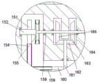
Advantageously, the irradiation assembly comprises an ultraviolet irradiation cavity 46 located in the ultraviolet sterilization box 48, the left and right end walls of the ultraviolet irradiation cavity 46 are rotatably mounted by a twenty-fourth shaft 45, a thirty-third gear 47 is fixedly mounted on the twenty-fourth shaft 45, the ultraviolet sterilization box 48 and the ultraviolet irradiation cavity 46 are internally provided with an ultraviolet irradiation device, a thirty-first helical gear 162 fixedly mounted on a twenty-first shaft 161 is arranged above a twenty-seventh gear 160, a thirty-second helical gear 165 is arranged on the left side of the thirty-first helical gear 162 in a gear engagement manner, the thirty-second helical gear 165 is fixedly mounted on a twenty-fifth shaft 158, the twenty-fifth shaft 158 is rotatably mounted in the end wall of the transmission cavity 172, a ninth belt connecting part 155 is arranged on the left side of the thirty-second helical gear 165, a belt pulley in the ninth belt connecting part 155 is fixedly mounted on the twenty-fifth shaft 158, another pulley in the ninth belt connecting component 155 is fixedly installed on a twenty-sixth shaft 152, the twenty-sixth shaft 152 is rotatably installed in the end wall of the transmission cavity 172, a thirty-third gear 151 on the left side of the ninth belt connecting component 155 is fixedly installed on the twenty-sixth shaft 152, the thirty-third gear 151 and the thirty-third gear 47 are connected by a tenth magnetic chain 154, a tenth belt connecting component 147 fixedly installed on a nineteenth shaft 143 is arranged below the twenty-fifth gear 141, one pulley in the tenth belt connecting component 147 is fixedly installed on the nineteenth shaft 143, another pulley in the tenth belt connecting component 147 is fixedly installed on a twenty-seventh shaft 146, the twenty-seventh shaft 146 is rotatably installed in the end wall of the transmission cavity 172, and a thirty-fourth gear 145 below the tenth belt connecting component 147 is fixedly installed on the twenty-seventh shaft 146, a thirty-fifth gear 35 is arranged on the right side of the thirty-fourth gear 145, the thirty-fourth gear 145 and the thirty-fifth gear 35 are connected by an eleventh magnetic chain 37, the thirty-fifth gear 35 is fixedly installed on a twenty-eighth shaft 36, and the twenty-eighth shaft 36 is rotatably installed in the end wall of the transmission cavity 172.
Advantageously, the storage assembly comprises a storage cavity 39 arranged in the storage box 40, a plurality of storage magnets 43 are arranged on the end walls of the storage cavity 39, a twenty-ninth shaft 41 is rotatably mounted on the left and right end walls of the storage cavity 39, a thirty-sixth gear 42 is fixedly mounted on the twenty-ninth shaft 41, a thirty-seventh helical gear 163 is arranged on the right side of the thirty-eleventh helical gear 162 in a gear engagement manner, the thirty-seventh helical gear 163 is fixedly mounted on a twenty-fifth shaft 158, an eleventh belt connecting component 32 is arranged on the right side of the thirty-seventh helical gear 163, one belt pulley in the eleventh belt connecting component 32 is fixedly mounted on the twenty-fifth shaft 158, the other belt pulley in the eleventh belt connecting component 32 is fixedly mounted on the thirty-fifth shaft 30, and the thirty-shaft 30 is rotatably mounted in the end wall of the transmission cavity 172, the thirty-third shaft 30 is fixedly provided with a thirty-eighth gear 33 positioned on the right side of the eleventh belt connecting component 32, and the thirty-eighth gear 33 and the thirty-sixth gear 42 are connected by a twelfth magnetic chain 38.
Advantageously, the magnetic properties of the second magnetic chain 2 are less than those of the first magnetic chain 80, the magnetic properties of the first magnetic chain 80 are less than those of the third magnetic chain 128, the magnetic properties of the third magnetic chain 128 are less than those of the fourth magnetic chain 132, the magnetic properties of the fourth magnetic chain 132 are less than those of the fifth magnetic chain 131, the magnetic properties of the fifth magnetic chain 131 are less than those of the sixth magnetic chain 119, the magnetic properties of the sixth magnetic chain 119 are less than those of the seventh magnetic chain 140, the magnetic properties of the seventh magnetic chain 140 are less than those of the ninth magnetic chain 26, the magnetic properties of the ninth magnetic chain 26 are less than those of the eighth magnetic chain 159, the magnetic properties of the eighth magnetic chain 159 are less than those of the tenth magnetic chain 154, the magnetic properties of the tenth magnetic chain 154 are less than those of the eleventh magnetic chain 37, the magnetic chain 37 are less than those of the twelfth magnetic chain 38, the magnetic property of the twelfth magnetic chain 38 is smaller than that of the storage magnet 43.
When the work is started;
1. the fan motor 182 and the driving motor 63 are started, the driving motor 63 drives the lower fan shaft 62 to rotate, the lower fan shaft 62 rotates to rotate the twentieth gear 58 and the lower stirrer fan 61, the twentieth gear 58 rotates to rotate the nineteenth gear 57, the nineteenth gear 57 rotates to rotate the fifteenth shaft 56, the fifteenth shaft 56 rotates to rotate the drying fan 54, the drying fan 54 rotates to rotate, the nineteenth gear 57 rotates to drive the left transmission gear 50 to rotate, the left transmission gear 50 rotates to drive the stirring fan in the sterilizing box 167 to rotate, the left transmission gear 50 rotates to drive the right transmission gear 49 to rotate, and the right transmission gear 49 rotates to drive the drying fan in the right drying box to rotate.
2. The lower fan shaft 62 rotates to drive the twentieth gear 58 to rotate and drive the first belt pulley 64 to rotate, the first belt pulley 64 rotates to drive the second belt pulley 67 to rotate through the rotating belt 65, the second belt pulley 67 rotates to drive the first shaft 68 to rotate, the first shaft 68 rotates to drive the third belt pulley 171 to rotate, the third belt pulley 171 rotates to drive the fourth belt pulley 86 to rotate through the transmission belt 1, the fourth belt pulley 86 rotates to drive the second shaft 92 to rotate, the second shaft 92 rotates to drive the eighth bevel gear 93 to rotate, the eighth bevel gear 93 rotates to drive the seventh bevel gear 94 to rotate, the seventh bevel gear 94 rotates to drive the fifth shaft 95 to rotate, and the fifth shaft 95 rotates to drive the fourth shaft 98 to rotate through the first belt connecting part 101, the fourth shaft 98 rotates to drive the sixth gear 100 to rotate, and the sixth gear 100 rotates to drive the fifth gear 79 to rotate through the first magnetic chain 80.
3. The first shaft 68 rotates to drive the third belt pulley 171 to rotate and drive the tenth gear 173 to rotate, the tenth gear 173 rotates to drive the second magnetic chain 2 to rotate, the second magnetic chain 2 attracts the magnet 174 at the lower end of the gastroscope 170 in the lower slide cavity 88 to the second magnetic chain 2, and then drives the gastroscope 170 to enter the cleaning cavity 77 for cleaning, the tenth gear 173 rotates to drive the eleventh gear 6 to rotate through the second magnetic chain 2, when the gastroscope 170 rotates on the second magnetic chain 2 and passes through the first magnetic chain 80, since the magnetic force on the first magnetic chain 80 is greater than that on the second magnetic chain 2, the first magnetic chain 80 attracts the first magnetic chain 80, the eleventh gear 6 rotates to drive the eighth shaft 7 to rotate, and the eighth shaft 7 rotates to drive the tenth shaft 11 to rotate through the third belt coupling part 10, the tenth shaft 11 rotates to drive the fourteenth helical gear 12 to rotate, the fourteenth helical gear 12 rotates to drive the fifteenth helical gear 14 to rotate, the fifteenth helical gear 14 rotates to drive the eleventh shaft 15 to rotate, the tenth shaft 15 rotates to drive the twelfth shaft 139 to rotate through the fourth belt connecting part 134, the twelfth shaft 139 rotates to drive the sixteenth gear 137 to rotate, the sixteenth gear 137 rotates to drive the seventeenth gear 52 to rotate through the fourth magnetic chain 132, the seventeenth gear 52 rotates, when the gastroscope 170 enters the cleaning cavity 77 for cleaning, the water flows fast due to the rotation of the upper stirring fan 180, so that the water can be cleaned more thoroughly, and the generated sewage enters the lower flow cavity 74 and then enters the upper filter plate 72 for filtering through the pressure one-way valve 73, the filtered water enters the cleaning connection cavity 71, and is filtered by the lower filter plate 69 to clean the sewage, and then enters the cleaning cavity 75, then the sewage flows to both sides under the driving of the lower stirring fan 61 in the cleaning cavity 75, and then enters the cleaning cavity 77 again, then the gastroscope 170 adsorbs the gastroscope 170 from the first magnetic chain 80 to the third magnetic chain 128 through the third magnetic chain 128, then the gastroscope 170 adsorbs from the third magnetic chain 128 to the fourth magnetic chain 132 through the fourth magnetic chain 132, and then enters the left drying box 83 to be dried, and the left drying box 83 is further provided with the drying fan 54 to accelerate the drying.
4. When the gastroscope 170 passes through the fifth magnetic chain 131 and is attracted to the fifth magnetic chain 131 from the fourth magnetic chain 132, the second shaft 92 rotates to drive the eighth bevel gear 93 to rotate and simultaneously drive the seventh shaft 5 to rotate through the second belt connecting part 3, the seventh shaft 5 rotates to drive the ninth gear 4 to rotate, the ninth gear 4 rotates to drive the twelfth gear 127 to rotate through the third magnetic chain 128, the twelfth gear 127 rotates to drive the ninth shaft 126 to rotate, the ninth shaft 126 rotates to drive the eighteenth shaft 124 to rotate through the sixth belt connecting part 125, the eighteenth shaft 124 rotates to drive the twenty-fourth gear 121 to rotate, and the twenty-fourth gear 121 rotates to drive the twenty-fifth gear 141 through the seventh magnetic chain 140, the twenty-fifth gear 141 rotates to drive the nineteenth shaft 143 to rotate, the nineteenth shaft 143 rotates to drive the twenty-seventh shaft 146 to rotate through the tenth belt connecting part 147, the twenty-seventh shaft 146 rotates to drive the thirty-fourth gear 145 to rotate, and the thirty-fourth gear 145 rotates to drive the thirty-fifth gear 35 to rotate through the eighth magnetic chain 159.
5. The tenth shaft 11 rotates to drive the fourteenth helical gear 12 to rotate and simultaneously drive the thirteenth gear 16 to rotate, the thirteenth gear 16 rotates to drive the eighteenth gear 113 to rotate, the eighteenth gear 113 rotates to drive the fourteenth shaft 114 to rotate, the fourteenth shaft 114 rotates to drive the twenty-first helical gear 112 to rotate, the twenty-first helical gear 112 rotates to drive the twenty-second helical gear 111 to rotate, the twenty-second helical gear 111 rotates to drive the sixteenth shaft 110 to rotate, the sixteenth shaft 110 rotates to drive the seventeenth shaft 106 to rotate through the fifth belt connecting part 107, the seventeenth shaft 106 rotates to drive the twenty-third gear 105 to rotate, the twenty-third gear 105 rotates to drive the fifth gear 79 in the disinfection box 167 to rotate through the sixth magnetic chain 119, the gastroscope 170 passes through the sixth magnetic chain 119 and is attracted to the sixth magnetic chain 119 from the fifth magnetic chain 131, and then enters the sterilizing box 167 to be sterilized by contacting with the sterilizing liquid therein.
6. The twenty-first bevel gear 112 rotates to drive the twenty-second bevel gear 111 to rotate and simultaneously drive the twenty-eighth bevel gear 17 to rotate, the twenty-eighth helical gear 17 rotates to drive the twenty-second shaft 18 to rotate, the twenty-second shaft 18 rotates to drive the twenty-third shaft 23 to rotate through the eighth belt connecting part 21, the twenty-third shaft 23 rotates to drive the twenty-ninth gear 24 to rotate, the twenty-ninth gear 24 rotates through the ninth magnetic chain 26 to drive the gears in the right drying box to rotate, the sterilized materials are taken out by the sixth magnetic chain 119 and pass through the seventh magnetic chain 140 to be adsorbed onto the seventh magnetic chain 140, the gastroscope 170 is then attracted to the ninth magnetic chain 26 by the ninth magnetic chain 26, then enters the right drying box 166 for drying, is taken out by the ninth magnetic chain 26 and is attracted to the eighth magnetic chain 159.
7. The fourteenth shaft 114 rotates to drive the twenty-first helical gear 112 to rotate and simultaneously drive the twentieth shaft 116 to rotate through the seventh belt connecting part 115, the twentieth shaft 116 rotates to drive the twenty-sixth gear 117 to rotate, the twenty-sixth gear 117 rotates to drive the twenty-eighth gear 160 to rotate through the eighth magnetic chain 159, the twenty-eighth gear 160 rotates to drive the twenty-first shaft 161 to rotate, the twenty-first shaft 161 rotates to drive the thirty-eleventh helical gear 162 to rotate, the thirty-second helical gear 162 rotates to drive the thirty-second helical gear 165 to rotate, the thirty-second helical gear 165 rotates to drive the twenty-fifth shaft 158 to rotate, and the twenty-fifth shaft 158 rotates to drive the twenty-sixth shaft 152 to rotate through the ninth belt connecting part 155, the twenty-sixth shaft 152 rotates to drive the thirty-third gear 151 to rotate, the thirty-third gear 151 rotates to drive the thirty-third gear 47 to rotate through the tenth magnetic chain 154, the gastroscope 170 adsorbed to the eighth magnetic chain 159 passes through the tenth magnetic chain 154, is adsorbed to the tenth magnetic chain 154, is then taken into the ultraviolet disinfection box 48 to be disinfected again, and is then taken out by the tenth magnetic chain 154 to pass through the eleventh magnetic chain 37 and be adsorbed to the eleventh magnetic chain 37.
8. The thirty-first helical gear 162 rotates to drive the thirty-second helical gear 165 to rotate and simultaneously drive the thirty-seventh helical gear 163 to rotate, the thirty-seventh helical gear 163 rotates to drive the twenty-fifth shaft 158 to rotate, the twenty-fifth shaft 158 rotates to drive the thirty-third shaft 30 to rotate through the eleventh belt connecting component 32, the thirty-third shaft 30 rotates to drive the thirty-eighth gear 33 to rotate, the thirty-eighth gear 33 rotates through the twelfth magnetic chain 38 to drive the thirty-sixth gear 42 to rotate, then the gastroscope 170 passes through the twelfth magnetic chain 38, is attracted to the twelfth magnetic chain 38 from the eleventh magnetic chain 37 and then enters the storage box 40, and enters the storage box 40 and is attracted to the storage magnet 43 when passing through the storage magnet 43, the cleaned and sterilized magnets are then stored in the storage box 40.
The above description is only an embodiment of the invention, but the scope of the invention is not limited thereto, and any changes or substitutions that are not thought of through the inventive work should be included in the scope of the invention. Therefore, the protection scope of the invention should be subject to the protection scope defined by the claims.