CN111119528B - Isolation shelter for infectious disease prevention and control - Google Patents
Isolation shelter for infectious disease prevention and control Download PDFInfo
- Publication number
- CN111119528B CN111119528B CN202010098139.XA CN202010098139A CN111119528B CN 111119528 B CN111119528 B CN 111119528B CN 202010098139 A CN202010098139 A CN 202010098139A CN 111119528 B CN111119528 B CN 111119528B
- Authority
- CN
- China
- Prior art keywords
- frame
- wall
- shelter
- keel frame
- support
- Prior art date
- Legal status (The legal status is an assumption and is not a legal conclusion. Google has not performed a legal analysis and makes no representation as to the accuracy of the status listed.)
- Expired - Fee Related
Links
- 238000002955 isolation Methods 0.000 title claims abstract description 23
- 208000035473 Communicable disease Diseases 0.000 title claims abstract description 17
- 230000006806 disease prevention Effects 0.000 title claims abstract description 10
- 208000015181 infectious disease Diseases 0.000 title claims abstract description 10
- 238000000034 method Methods 0.000 claims description 11
- 230000008569 process Effects 0.000 claims description 11
- 229910000831 Steel Inorganic materials 0.000 claims description 5
- 239000010959 steel Substances 0.000 claims description 5
- 230000002265 prevention Effects 0.000 claims description 3
- 238000010276 construction Methods 0.000 abstract description 4
- 239000000463 material Substances 0.000 abstract description 3
- 238000010586 diagram Methods 0.000 description 9
- 210000001503 joint Anatomy 0.000 description 4
- 238000005267 amalgamation Methods 0.000 description 3
- 230000007704 transition Effects 0.000 description 3
- 201000010099 disease Diseases 0.000 description 2
- 208000037265 diseases, disorders, signs and symptoms Diseases 0.000 description 2
- 230000032258 transport Effects 0.000 description 2
- 230000007306 turnover Effects 0.000 description 2
- 230000006978 adaptation Effects 0.000 description 1
- 238000003491 array Methods 0.000 description 1
- 230000007547 defect Effects 0.000 description 1
- 238000012986 modification Methods 0.000 description 1
- 230000004048 modification Effects 0.000 description 1
- 230000000149 penetrating effect Effects 0.000 description 1
Images




Classifications
-
- E—FIXED CONSTRUCTIONS
- E04—BUILDING
- E04H—BUILDINGS OR LIKE STRUCTURES FOR PARTICULAR PURPOSES; SWIMMING OR SPLASH BATHS OR POOLS; MASTS; FENCING; TENTS OR CANOPIES, IN GENERAL
- E04H3/00—Buildings or groups of buildings for public or similar purposes; Institutions, e.g. infirmaries or prisons
- E04H3/08—Hospitals, infirmaries, or the like; Schools; Prisons
-
- E—FIXED CONSTRUCTIONS
- E04—BUILDING
- E04B—GENERAL BUILDING CONSTRUCTIONS; WALLS, e.g. PARTITIONS; ROOFS; FLOORS; CEILINGS; INSULATION OR OTHER PROTECTION OF BUILDINGS
- E04B1/00—Constructions in general; Structures which are not restricted either to walls, e.g. partitions, or floors or ceilings or roofs
- E04B1/343—Structures characterised by movable, separable, or collapsible parts, e.g. for transport
Landscapes
- Engineering & Computer Science (AREA)
- Architecture (AREA)
- Civil Engineering (AREA)
- Structural Engineering (AREA)
- Physics & Mathematics (AREA)
- Electromagnetism (AREA)
- Health & Medical Sciences (AREA)
- Public Health (AREA)
- Accommodation For Nursing Or Treatment Tables (AREA)
Abstract
The invention discloses an isolation shelter for infectious disease prevention and control, which comprises a shelter base, a keel frame and a wall module, wherein the keel frame is arranged on the shelter base; the keel frame is arranged on the shelter base, and the plurality of groups of wall body modules are arranged on the periphery and the top of the keel frame; the keel frame can be folded; the wall body module consists of two groups of foldable supports and a plurality of wallboards arranged between the two groups of foldable supports; the wall module can be switched between a folded state and an unfolded state. The isolation shelter for infectious disease prevention and control has the advantages that the foldable keel frame and the modular wall body module are designed, so that the operation is very convenient when the isolation shelter is assembled, the construction time is short, and the keel frame and the wall body module are arranged in a foldable mode, so that the keel frame and the wall body module are convenient to transport and store as strategic materials in a folded state.
Description
Technical Field
The invention relates to the technical field of medical facilities, in particular to an isolation shelter for preventing and controlling infectious diseases.
Background
When infectious diseases occur in the human society, the isolation measures are adopted to carry out closed observation on infected persons and suspected infected persons, so that the effective means for preventing and controlling the infectious diseases is provided, when a large number of cases of the infectious diseases exist, the infected persons and the suspected infected persons need to enter independent isolation rooms for isolation, the number of the isolation rooms is generally difficult to meet the requirements, and therefore the isolation shelter needs to be used.
Disclosure of Invention
The purpose of the invention is as follows: in order to overcome the defects in the prior art, the invention provides the isolating shelter for infectious disease prevention and control, which is quick to assemble and short in construction time.
The technical scheme is as follows: in order to achieve the purpose, the isolation shelter for infectious disease prevention and control comprises a shelter base, a keel frame and a wall module;
the keel frame is arranged on the shelter base, and the plurality of groups of wall body modules are arranged on the periphery and the top of the keel frame;
the keel frame can be folded;
the wall body module consists of two groups of foldable supports and a plurality of wallboards arranged between the two groups of foldable supports; the wall module can be switched between a folded state and an unfolded state.
Further, the shelter base comprises a hollow base frame, a leg unit and a bottom plate; the upper side of the supporting leg unit is provided with a connecting plate; the base frames are spliced into a frame group, and the corner parts of the adjacent base frames are fixed on the connecting plate on the same supporting leg unit; the base plate is mounted on the base frame.
Further, the base frame is made of angle steel, and is provided with an accommodating groove with an upward opening, and the bottom plate is arranged in the accommodating groove.
Further, the keel frame comprises a top frame, a bottom frame, a first side frame and a second side frame; the first side frame is composed of two frame units which are hinged with each other; the upper side and the lower side of the first side frame are respectively hinged on the top frame and the bottom frame; the second side frame is hinged relative to the bottom frame; when the keel frame is in an unfolded state, the whole keel frame is in a cuboid structure; when the keel frame is in a folded state, the two frame units of the first side frame are folded together and arranged between the top frame and the bottom frame, and the second side frame is overturned and arranged on the upper side of the top frame.
Furthermore, the two groups of foldable supports of the same wall module are respectively composed of a first support unit and a second support unit; the first support unit is provided with a clamping groove, and the second support unit is provided with a clamping edge matched with the clamping groove for use.
Has the advantages that: the isolation shelter for infectious disease prevention and control has the advantages that the foldable keel frame and the modular wall body module are designed, so that the operation is very convenient when the isolation shelter is assembled, the construction time is short, and the keel frame and the wall body module are arranged in a foldable mode, so that the keel frame and the wall body module are convenient to transport and store as strategic materials in a folded state.
Drawings
FIG. 1 is a view showing the outline of an isolation shelter for infectious disease prevention and control;
FIG. 2 is a structural view of the keel frame in an unfolded state;
fig. 3 is a structural view of the keel frame in an intermediate state from an unfolded state to a folded state;
FIG. 4 is a structural view of the keel frame in a folded state;
FIG. 5 is a block diagram of the shelter base;
FIG. 6 is a view showing a connection structure of the base frame and the leg unit;
figure 7 is a block diagram of a wall module in a folded state;
FIG. 8 is an enlarged view of portion A of FIG. 7;
FIG. 9 is an enlarged view of portion B of FIG. 7;
FIG. 10 is a block diagram of a wall module in a semi-deployed state;
FIG. 11 is a block diagram of a wall module in an expanded state;
FIG. 12 is a block diagram of a wall panel;
FIG. 13 is a structural view of a first stand unit;
FIG. 14 is a structural view of a second holder unit;
FIG. 15 is an assembled structure view of a wall module and a keel frame;
fig. 16 is an exploded view of the wall module and keel frame assembled together;
fig. 17 is a first perspective view block diagram of a first state of the process of installing a wall module to a keel frame;
fig. 18 is a second perspective view of the first state of the process of installing a wall module to a keel frame;
Figure 19 is a first perspective view block diagram of a second state of the process of installing a wall module to a keel frame;
fig. 20 is a second perspective view block diagram of a second state of the process of installing a wall module to a keel frame;
figure 21 is a third state block diagram of the process of installing a wall module to a keel frame.
In the figure: 1-a foldable support; 11-a multi-segment scaffold unit; 111-a chute; 122 — first slot edge; 123-a second slot edge; 124-mounting holes; 125-boss portion; 126-rotation stop groove; 127-a first plane; 128-a second plane; 129-a transition bevel; 12-a first rack unit; 13-a second rack unit; 121-a clamping groove; 124-mounting holes; 131-clamping edges; 2-wallboard; 21-a glide part; 22-a boss; 23-a groove section; 3-shelter base; 31-a base frame; 32-a leg unit; 33-a connecting plate; 34-a bottom plate; 4-a fixing piece; 41-a rod part; 411-bar-shaped portion; 412-a slide guide hole; 42-a handle bar; 5-keel frame; 51-a top frame; 52-bottom frame; 53-first side frame; 531-a frame unit; 54-a second side frame; 6-hinge.
Detailed Description
The present invention will be further described with reference to the accompanying drawings.
The isolation shelter for infectious disease prevention and control shown in the attached figure 1 comprises a shelter base 3, a keel frame 5 and a wall module; the keel frame 5 is arranged on the shelter base 3, and the plurality of groups of wall body modules are arranged on the periphery and the top of the keel frame 2; the keel frame 5 can be folded; the wall body module consists of two groups of foldable brackets 1 and a plurality of wallboards 2 arranged between the two groups of foldable brackets 1; the wall module can be switched between a folded state and an unfolded state.
Above-mentioned pass catch disease is isolation shelter for prevention and control, through the wall body module of folding keel frame 5 of design and modular for the operation is very convenient during the equipment isolation shelter, and the engineering time is short, and because keel frame 5 and wall body module all are collapsible setting, and occupation space is little under both fold condition, conveniently transports and invents as strategic material, and when the pass catch disease comes, can allocate the equipment fast, and mobility is strong.
As shown in fig. 5 to 6, the shelter base 3 comprises a hollow base frame 31, a leg unit 32 and a bottom plate 34; a connection plate 33 is provided on the upper side of the leg unit 32; a plurality of base frames 31 are combined into a frame group, and the corner parts of the adjacent base frames 31 are fixed on the connecting plate 33 on the same leg unit 32; the base plate 34 is mounted on the base frame 31. Specifically, the base frame 31 is made of angle steel, and has a receiving groove with an upward opening, one side edge of the angle steel serves as a side flange of the receiving groove, the other side edge of the angle steel serves as a lower flange of the receiving groove, and the bottom plate 34 is disposed in the receiving groove. Adopt the shelter base 3 of above-mentioned structure, it adopts overhead structure for keep apart the shelter and can establish in the open air, and effectively with the whole frame of shelter off-ground, make the shelter bottom can not receive the moisture on ground.
As shown in fig. 2 to 4, the keel frame 5 includes a top frame 51, a bottom frame 52, a first side frame 53 and a second side frame 54; the first side frame 53 is composed of two frame units 531 hinged to each other; the upper and lower sides of the first side frame 53 are respectively hinged to the top frame 51 and the bottom frame 52; the second side frame 54 is hinged with respect to the bottom frame 52; when the keel frame 5 is in an unfolded state, the whole keel frame is in a cuboid structure; when the keel frame 5 is in a folded state, the two frame units 531 of the first side frame 53 are folded together and placed between the top frame 51 and the bottom frame 52, and the second side frame 54 is placed upside down on the top frame 51.
The keel frame 5 adopting the structure is convenient to unfold and fold, and the unfolding process from the folded state (as shown in the attached figure 4) is as follows: first, the two frame units 531 included in the first side frame 53 are relatively unfolded and fixed, so that the top frame 51 and the bottom frame 52 are relatively separated (the middle state is shown in fig. 3), and then the two second side frames 54 are turned down from the upper side of the top frame 51 and fixed relative to the first side frame 53 and the bottom frame 52, so that the erecting operation of the keel frame 5 is completed, and the construction speed is very high.
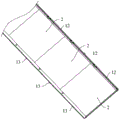
As shown in fig. 7, the wall module includes a foldable bracket 1 and a wall plate 2; a plurality of wall plates 2 are arranged between the two foldable supports 1; the foldable support 1 is composed of a plurality of sections of support units 11, adjacent support units 11 are connected through hinges 6, and each support unit 11 is provided with a sliding groove 111 extending along the length direction of the support unit; sliding parts 21 (shown in fig. 12) which can slide in the sliding grooves 111 are symmetrically arranged on both sides of the wall plate 2; the whole device can be switched between a folded state and an unfolded state; in a folded state, as shown in fig. 7-9, all the rack units 11 are stacked together, two ends of all the rack units 11 are aligned and arranged side by side, all the wall panels 2 are stacked, the stacking direction of the rack units 11 is perpendicular to the stacking direction of the wall panels 2, and the sliding portions 21 of all the wall panels 2 on the same side are all placed in the sliding grooves 111 of the same rack unit 11; therefore, the whole wall body module can be folded into a square block with a small size, and the transportation convenience is greatly improved. In the unfolded state, as shown in fig. 10, all the support units 11 are arranged in a straight line, and the sliding grooves 111 on each support unit 11 are spliced into continuous straight through grooves; all the wall boards 2 are in a flat state, the linear arrays are arranged between the two folding frameworks 1, and the end faces of all the wall boards 2 are flush.
Make each wallboard 2 for folded cascade support 1 quick fixation under the state of realizing unfolding, in two adjacent wallboards 2, the butt joint can be carried out to both adjacent sides, specifically is: in a pair of side edges of the wall plate 2 (the wall plate 2 is square, one of the two side edges is two, two sliding parts 21 are arranged in the other pair of side edges of the wall plate 2, and the sliding parts 21 are located at one end of the side edge where the sliding parts are located), a protruding part 22 is formed at one side edge, and a groove part 23 is formed at the other side edge; in the unfolded state, the protruding part 22 of one wall plate 2 is embedded into the groove part 23 of the other wall plate 2 in every two adjacent wall plates 2. Adopt above-mentioned structure, all wallboard 2 between two folded cascade supports 1 are end to end butt joint in proper order, so, one side of wallboard 2 realizes fixing through the portion 21 that slides of embedding in spout 111, and the opposite side is fixed with the help of its adjacent wallboard 2 realization, need not plus unnecessary mounting 4.
The process of switching from the folded state to the unfolded state is as follows:
firstly, unfolding the foldable support 1 to enable all the support units 11 to be arranged in a straight line, and combining the sliding grooves 111 on all the support units 11 into a continuous straight through groove;
Then, turn over each wallboard 2 to the flat state in proper order, and start from second wallboard 2, every turn over a wallboard 2, with last wallboard 2 amalgamation for the bellying 22 of a wallboard 2 imbeds to the concave groove portion 23 of another wallboard 2, and the completion is turned over and the amalgamation to all wallboard 2. In the assembling process, the assembled wall panel set gradually grows, and the sliding portion 21 of the wall panel 2 slides along the sliding groove 111.
Preferably, when wallboard 2 is in the flat state, the length of wallboard 2 on the extending direction of foldable support 1 and the length of every support unit 11 are different, so, under the expansion state, the butt joint position of per two wallboards 2 staggers each other with the rotation hookup location of per two support units 11 on foldable support 1, so, the foldable support 1 of expansion can support each other with the wallboard group that the amalgamation was accomplished, is in the stable in structure of the wall body module of expansion state.
Preferably, in order to facilitate the mutual butt joint of the wall modules in the unfolded state, the bracket unit 11 includes two types of bracket units, namely a first bracket unit 12 and a second bracket unit 13, wherein a clamping groove 121 (as shown in fig. 13) is formed on the first bracket unit 12, and a clamping edge 131 (as shown in fig. 14) is formed on the second bracket unit 13; of the two sets of foldable brackets 1, one set of foldable brackets 1 is formed by the first bracket unit 12, and the other set of foldable brackets 1 is formed by the second bracket unit 13.
Through the structure, between two adjacent wall modules in the unfolded state, the clamping edge 131 on the foldable support 1 formed by the second support unit 13 of one of the wall modules can be embedded into the clamping groove 121 on the foldable support 1 formed by the first support unit 12, so that the wall modules are butted to form a wallboard with a larger area.
In addition, in order to fix the wall module in the unfolded state with respect to the keel frame 5, a first slot edge 122 and a second slot edge 123 are respectively disposed at two sides of the clamping slot 121, as shown in fig. 13, wherein the second slot edge 123 is wider than the first slot edge 122, and a mounting hole 124 is formed on the second slot edge 123. Thus, the wall body modules can be fixed on the building keel frame 5 through the fixing pieces 4 penetrating through the mounting holes 124, and after one group of wall body modules are fixed, the other group of wall body modules are butted with the other group of wall body modules, and then the fixing pieces 4 can be shielded (as shown in figures 15-16), so that the fixing pieces 4 cannot be exposed, and the assembled wall body is high in integrity, simple and attractive.
Preferably, the second groove edge 123 is formed with a boss 125 and a rotation stopping groove 126, the boss 125 is formed with a profile including a first plane 127, a second plane 128 and a transition slope 129 disposed between the first plane 127 and the second plane 128, the first plane 127 is lower than the second plane 128; the mounting hole 124 penetrates the entire boss portion 125 and the second groove edge 123, and the mounting hole 124 includes a circular hole portion and an extending groove extending outward in a radial direction of the circular hole portion. The keel frame 5 is formed with a fixing hole having a shape corresponding to the shape of the mounting hole 124.
The fixing part 4 comprises a round rod part 41 and a handle rod 42, one end of the rod part 41 is provided with a strip part 411 which extends outwards along the radial direction of the rod part, and the other end of the rod part 41 is provided with a guide sliding hole 412 which penetrates through the rod part along the radial direction of the rod part; the handle bar 42 passes through the slide guide hole 412 and can slide along the slide guide hole 412.
With the above structure, when the wall module needs to be fixed to the keel frame 5, first, the mounting hole 124 of the wall module is aligned with the fixing hole on the keel frame 5, and then the end of the rod part 41 with the strip part 411 is passed through the mounting hole 124 and the fixing hole, so that the strip part 411 reaches the back side of the keel frame 5 (as shown in fig. 17-18), and the handle bar 42 is attached to the first plane 127; then, rotating the handle bar 42 to make the handle bar 42 climb to the second plane 128 along the transition slope 129, in the process, the handle bar 42 drives the rod part 41 to rotate and make the strip part 411 abut against the back side of the keel frame 5 (as shown in fig. 19-20); finally, the handle bar 42 is pushed to slide along the slide guide hole 412, so that one end of the handle bar 42 is inserted into the rotation stop groove 126, and the handle bar 42 cannot rotate (as shown in fig. 21). Through the mode, the wall body module can be conveniently fixed, traditional fasteners such as screws are not needed, and the operation is fast and convenient.
The above description is only of the preferred embodiments of the present invention, and it should be noted that: it will be apparent to those skilled in the art that various modifications and adaptations can be made without departing from the principles of the invention and these are intended to be within the scope of the invention.
Claims (5)
1. An isolation shelter for infectious disease prevention and control is characterized by comprising a shelter base, a keel frame and a wall module;
the keel frame is arranged on the shelter base, and the plurality of groups of wall body modules are arranged on the periphery and the top of the keel frame;
the keel frame can be folded;
the wall body module consists of two groups of foldable supports and a plurality of wallboards arranged between the two groups of foldable supports; the wall body module can be switched between a folded state and an unfolded state;
the foldable support is composed of a plurality of sections of support units, the adjacent support units are hinged, and each support unit is provided with a sliding groove extending along the length direction of the support unit; sliding parts capable of sliding in the sliding grooves are symmetrically arranged on two sides of the wall plate; the whole foldable support can be switched between a folded state and an unfolded state; in a folded state, two ends of all the support units are aligned and arranged side by side, all the wallboards are stacked, and the sliding parts on the same side of all the wallboards are arranged in the sliding grooves of the same support unit; in the unfolded state, all the support units are arranged in a straight line, and the sliding grooves on the support units are spliced into continuous straight through grooves; all the wall boards are arranged between the two folding frameworks in a linear array mode, and the end faces of all the wall boards are flush;
The wall plate is square, and a protruding part is formed on one side edge of a pair of side edges of the wall plate, and a groove part is formed on the other side edge of the wall plate; in the unfolded state, the protruding part of one wall plate is embedded into the groove part of the other wall plate in every two adjacent wall plates; the process that the wall body module is switched to the unfolding state from the folding state is as follows: firstly, unfolding the foldable support to enable all support units to be arranged in a straight line, and combining sliding grooves on all support units into a continuous straight through groove; then, all the wall boards are sequentially turned to be in a flat state, and from the second wall board, each wall board is turned over and spliced with the previous wall board, so that the protruding part of one wall board is embedded into the groove part of the other wall board until all the wall boards are turned over and spliced; in the splicing process, the spliced wallboard group gradually increases, and the sliding part of the wallboard slides along the sliding groove.
2. An isolation shelter for the prevention and control of infectious diseases as claimed in claim 1, wherein the shelter base comprises a hollow base frame, leg units and a floor; the upper side of the supporting leg unit is provided with a connecting plate; the base frames are spliced into a frame group, and the corner parts of the adjacent base frames are fixed on the connecting plate on the same supporting leg unit; the base plate is mounted on the base frame.
3. An isolation shelter as claimed in claim 2, wherein the base frame is made of angle steel and has a receiving groove with an upward opening, and the bottom plate is placed in the receiving groove.
4. An isolation shelter for the prevention and control of infectious diseases as claimed in claim 1, wherein said keel frame comprises a top frame, a bottom frame, a first side frame and a second side frame; the first side frame is composed of two frame units which are hinged with each other; the upper side and the lower side of the first side frame are respectively hinged on the top frame and the bottom frame; the second side frame is hinged relative to the bottom frame; when the keel frame is in an unfolded state, the whole keel frame is in a cuboid structure; when the keel frame is in a folded state, the two frame units of the first side frame are folded together and arranged between the top frame and the bottom frame, and the second side frame is overturned and arranged on the upper side of the top frame.
5. An isolation shelter for preventing and controlling infectious diseases as claimed in claim 1, wherein the two foldable supports of the same wall module are respectively composed of a first support unit and a second support unit; the first support unit is provided with a clamping groove, and the second support unit is provided with a clamping edge matched with the clamping groove for use.
Priority Applications (1)
| Application Number | Priority Date | Filing Date | Title |
|---|---|---|---|
| CN202010098139.XA CN111119528B (en) | 2020-02-18 | 2020-02-18 | Isolation shelter for infectious disease prevention and control |
Applications Claiming Priority (1)
| Application Number | Priority Date | Filing Date | Title |
|---|---|---|---|
| CN202010098139.XA CN111119528B (en) | 2020-02-18 | 2020-02-18 | Isolation shelter for infectious disease prevention and control |
Publications (2)
| Publication Number | Publication Date |
|---|---|
| CN111119528A CN111119528A (en) | 2020-05-08 |
| CN111119528B true CN111119528B (en) | 2021-10-26 |
Family
ID=70491300
Family Applications (1)
| Application Number | Title | Priority Date | Filing Date |
|---|---|---|---|
| CN202010098139.XA Expired - Fee Related CN111119528B (en) | 2020-02-18 | 2020-02-18 | Isolation shelter for infectious disease prevention and control |
Country Status (1)
| Country | Link |
|---|---|
| CN (1) | CN111119528B (en) |
Families Citing this family (5)
| Publication number | Priority date | Publication date | Assignee | Title |
|---|---|---|---|---|
| CN112237521B (en) * | 2020-10-11 | 2022-06-03 | 李星 | Assembled negative pressure isolation cabin |
| CN112282476B (en) * | 2020-10-20 | 2023-02-28 | 中国人民解放军火箭军特色医学中心 | Isolation negative pressure shelter for infectious disease prevention and control |
| CN112282274A (en) * | 2020-11-06 | 2021-01-29 | 安徽军瑶新型材料有限公司 | Foldable assembly type external wall panel keel for building and assembling method thereof |
| CN112459542A (en) * | 2020-12-09 | 2021-03-09 | 中国船舶工业系统工程研究院 | Modularization isolation ward |
| CN113969618A (en) * | 2021-07-01 | 2022-01-25 | 中国人民解放军军事科学院军事医学研究院 | A foldable combined modular P3 laboratory |
Citations (10)
| Publication number | Priority date | Publication date | Assignee | Title |
|---|---|---|---|---|
| CN2537756Y (en) * | 2002-03-25 | 2003-02-26 | 陈职新 | Folding house |
| KR20100121241A (en) * | 2009-05-08 | 2010-11-17 | 김광희 | A foldable large-scaled gate |
| CN202596117U (en) * | 2012-04-25 | 2012-12-12 | 魏其训 | Modularized and integrated antistatic floor support |
| CN204001204U (en) * | 2014-07-24 | 2014-12-10 | 潘教正 | Collapsible lightly constructed and simply equipped building |
| CN105386523A (en) * | 2015-10-31 | 2016-03-09 | 李红宾 | Expandable shelter |
| CN106917454A (en) * | 2015-12-28 | 2017-07-04 | 杜涛 | A kind of foldable template room |
| CN206815530U (en) * | 2017-06-13 | 2017-12-29 | 杨侃 | Side-foldable formula Multistage expanding shelter |
| CN109339243A (en) * | 2018-12-03 | 2019-02-15 | 江苏景中景工业涂装设备有限公司 | A foldable outdoor camping shelter |
| CN208792678U (en) * | 2018-09-11 | 2019-04-26 | 常州金海防静电地板有限公司 | A kind of honeycomb type Anti-electrostatic false floor |
| CN110080569A (en) * | 2019-05-28 | 2019-08-02 | 西安建筑科技大学建筑设计研究院 | Between a kind of Multifunctional sunlight |
Family Cites Families (1)
| Publication number | Priority date | Publication date | Assignee | Title |
|---|---|---|---|---|
| US20140090312A1 (en) * | 2004-10-04 | 2014-04-03 | Martin A. Medley | Convertible hard side shelter |
-
2020
- 2020-02-18 CN CN202010098139.XA patent/CN111119528B/en not_active Expired - Fee Related
Patent Citations (10)
| Publication number | Priority date | Publication date | Assignee | Title |
|---|---|---|---|---|
| CN2537756Y (en) * | 2002-03-25 | 2003-02-26 | 陈职新 | Folding house |
| KR20100121241A (en) * | 2009-05-08 | 2010-11-17 | 김광희 | A foldable large-scaled gate |
| CN202596117U (en) * | 2012-04-25 | 2012-12-12 | 魏其训 | Modularized and integrated antistatic floor support |
| CN204001204U (en) * | 2014-07-24 | 2014-12-10 | 潘教正 | Collapsible lightly constructed and simply equipped building |
| CN105386523A (en) * | 2015-10-31 | 2016-03-09 | 李红宾 | Expandable shelter |
| CN106917454A (en) * | 2015-12-28 | 2017-07-04 | 杜涛 | A kind of foldable template room |
| CN206815530U (en) * | 2017-06-13 | 2017-12-29 | 杨侃 | Side-foldable formula Multistage expanding shelter |
| CN208792678U (en) * | 2018-09-11 | 2019-04-26 | 常州金海防静电地板有限公司 | A kind of honeycomb type Anti-electrostatic false floor |
| CN109339243A (en) * | 2018-12-03 | 2019-02-15 | 江苏景中景工业涂装设备有限公司 | A foldable outdoor camping shelter |
| CN110080569A (en) * | 2019-05-28 | 2019-08-02 | 西安建筑科技大学建筑设计研究院 | Between a kind of Multifunctional sunlight |
Also Published As
| Publication number | Publication date |
|---|---|
| CN111119528A (en) | 2020-05-08 |
Similar Documents
| Publication | Publication Date | Title |
|---|---|---|
| CN111119528B (en) | Isolation shelter for infectious disease prevention and control | |
| US4779514A (en) | Portable building | |
| CA1064258A (en) | Portable display apparatus | |
| US3463218A (en) | Space divider | |
| US4118901A (en) | Structure for relocatable building with folding plate roof and folding end walls | |
| US3565152A (en) | Foldable partition | |
| US4166332A (en) | Portable display apparatus | |
| EP0293812B1 (en) | A portable display panel and hinge system | |
| WO1993021798A1 (en) | Folding display frame for forming column-like structures | |
| EP0173438A2 (en) | A tent frame | |
| USRE30777E (en) | Portable display system | |
| US2835931A (en) | Foldable shelter | |
| WO2008120071A2 (en) | Collapsible tent or marquee | |
| CN113892754B (en) | Telescopic folding table | |
| CA2221882C (en) | Collapsible panel and modular enclosure and partition system | |
| US4646657A (en) | Collapsible table | |
| RU2000131160A (en) | DEMO DEVICE | |
| EP3522754B1 (en) | Foldable cabinet | |
| CN107713356B (en) | Reversible telescopic dining table | |
| CN111287379B (en) | Fast vertical wall module for building | |
| JPH1061170A (en) | Knockdown temporary scaffold | |
| CN210407538U (en) | Reception table convenient to move | |
| JP3097887U (en) | Folding house | |
| US20070204772A1 (en) | Storage table system and method | |
| CN216641704U (en) | Modular cuts off rail |
Legal Events
| Date | Code | Title | Description |
|---|---|---|---|
| PB01 | Publication | ||
| PB01 | Publication | ||
| SE01 | Entry into force of request for substantive examination | ||
| SE01 | Entry into force of request for substantive examination | ||
| GR01 | Patent grant | ||
| GR01 | Patent grant | ||
| TR01 | Transfer of patent right | ||
| TR01 | Transfer of patent right |
Effective date of registration: 20220802 Address after: 511300 1701, building 14, Xincheng entrepreneurship center, Zengcheng low carbon headquarters park, No. 400 Xincheng Avenue, Zengcheng District, Guangzhou, Guangdong Province Patentee after: Zhichun new material technology (Guangzhou) Co.,Ltd. Address before: 301900 Hewan West Park, Zhongchang South Avenue, Jizhou, Tianjin Patentee before: Li Chaoyang |
|
| CF01 | Termination of patent right due to non-payment of annual fee | ||
| CF01 | Termination of patent right due to non-payment of annual fee |
Granted publication date: 20211026 |