Background
In order to prevent overheating of electronic devices, light emitting diode lighting lamps, or various components mounted in automobiles, which are currently used, cooling fans are mainly used.
The cooling fan includes: a rotating shaft rotatably supported by the fan housing; a rotor fixed to the rotating shaft; a stator fixed to the fan housing and disposed at a predetermined interval from the rotor; an impeller fixed to the rotor and rotating together with the rotor; and a Printed Circuit Board (PCB) disposed at a lower portion of the stator for controlling the cooling fan.
The cooling fan is equipped with a hall sensor for detecting the number of rotations of the rotor, and the hall sensor detects the number of rotations of the rotor by detecting a magnetic field generated in the magnet and is disposed at a position close to the magnet to the maximum.
As disclosed in korean patent laid-open publication No. 10-1482939(2015, 01/06), a hall sensor of a motor is mounted on a hall sensor substrate, which is disposed on one side of a heat insulating material fixing a stator, and is electrically connected to a cable through a main substrate of the motor.
Such a hall sensor has a structure that is provided at a position close to the magnet independently of the main substrate for controlling the motor and is connected to the main substrate, and therefore, there is a problem that the structure is complicated and the manufacturing cost is increased.
When the hall sensor is provided on the main substrate, the hall sensor is mounted on the upper surface of the main substrate, that is, at a position facing the magnet, and various circuit components are mounted on the rear surface of the main substrate, in order to provide the hall sensor at a position close to the magnet.
In this case, since the circuit component is mounted on the back surface of the main substrate and the hall sensor is mounted on the upper surface of the main substrate, there are problems that the number of manufacturing processes increases and the cost increases.
Disclosure of Invention
Technical problem
The invention aims to provide a cooling fan which increases the magnetic field intensity transmitted to a Hall sensor of a magnet so as to improve the sensing force of the Hall sensor.
Another object of the present invention is to provide a cooling fan in which a circuit component and a hall sensor are mounted on one surface of a printed circuit board, thereby reducing the manufacturing process and the cost.
Means for solving the problems
In order to solve the above problems, a cooling fan of the present invention includes: a fan housing; a rotating shaft rotatably supported by the fan housing; a stator fixed to the fan housing; a rotor provided on the rotating shaft, the rotor including a magnet and a back yoke, the magnet being disposed on an outer peripheral surface of the stator at a predetermined interval, the back yoke being disposed on an outer peripheral surface of the magnet; and a printed circuit board disposed under the stator, and mounted with a circuit component for controlling the cooling fan and a Hall sensor for detecting the number of rotations of the rotor, wherein a sensing force enhancing part is formed at a lower part of the magnet adjacent to the Hall sensor, and one of the length and the thickness is made larger than the other part to enhance the sensing force of the Hall sensor.
The circuit component and the hall sensor can be mounted on one surface of the printed circuit board by a primary component mounting process.
The sensing force enhancing part may include an expanding part that enhances the magnetic field strength in the lower direction by expanding the thickness of the lower portion of the magnet.
The magnet may have a cylindrical shape, and the extension portion may be formed to protrude in a circumferential direction on an outer surface of a lower portion of the magnet.
The expanding portion may protrude with the same width as the thickness of the back yoke.
The sensing force reinforcement part may include a protrusion part protruded toward a lower side direction of the magnet for increasing a length of the magnet.
The thickness of the protrusion may be thinner than the thickness of the other portion of the magnet.
The protrusion may have an inclined surface formed on an inner surface thereof so as to be thinner than other portions of the magnet.
ADVANTAGEOUS EFFECTS OF INVENTION
As described above, the present invention can increase the intensity of magnetic field generated at the lower portion adjacent to the hall sensor and improve the sensing performance of the hall sensor by forming the lower portion of the magnet having a large area.
Further, the circuit component and the hall sensor can be mounted together on the back surface of the printed circuit board by increasing the magnetic field strength detectable by the hall sensor, and thus, the printed circuit board can be manufactured by one component mounting process, and the manufacturing process can be shortened and the cost can be reduced.
Detailed Description
Embodiments of the present invention are described in detail below with reference to the several figures. In this process, the sizes, shapes, and the like of the components shown in the drawings are exaggerated for clarity and convenience. Also, a plurality of terms specifically defined in consideration of the structure and action of the present invention may be different according to the intention or custom of a user, an operator. These terms are defined throughout the specification.
Referring to fig. 1 and 2, the cooling fan of the present invention includes: a fan case 10 having an air outlet 12 formed on a front surface thereof for discharging air and an air inlet 14 formed on a rear surface thereof for allowing air to flow therein; a rotary shaft 20 rotatably supported by the fan housing 10; a rotor 30 fixed to the rotary shaft 20; a stator 40 fixed to the fan case 10 and disposed at a predetermined interval from the rotor 30; an impeller 50 connected to the rotor 30 and rotating together therewith; the printed circuit board 70 is disposed under the rotor 30 and the stator 40, connects the stator 40 to a power supply, and mounts various circuit components for controlling the cooling fan.
In order to allow air to pass through, the front and rear surfaces of the fan housing 10 are opened, and a support portion 60 is formed at the center thereof, and the support portion 60 supports the rotary shaft 20 so as to rotate the rotary shaft 20 and fixes the stator 40.
Fastening holes 64 for fixing to mounting brackets to which the cooling fan is mounted are formed in the corners of the fan casing 10.
The support portion 60 is formed in a cylindrical shape at the center of the fan housing 10, the rotary shaft 20 is rotatably inserted into the inner surface thereof, and the stator 40 is fixed to the outer surface thereof.
The rotary shaft 20 is rotatably supported by bearings 66 and 68 on the inner surface of the support portion 60. The bearings 66, 68 include: a first ball bearing 66 rotatably supporting an upper portion of the rotation shaft; and a second ball bearing 68 rotatably supporting a lower portion of the rotary shaft 20.
The stator 40 includes: an iron core 42 fixed to the outer peripheral surface of the support portion 60; a bobbin 44 mounted on an outer surface of the core 42; and a coil 46 wound around the bobbin 44 and supplied with power.
The rotor 30 includes: a magnet 32 arranged on the outer peripheral surface of the stator 40 at a predetermined interval and having a cylindrical shape; a back yoke 34 disposed on the outer peripheral surface of the magnet 32; and a rotor support 36 to which the magnet 32 and the back yoke 34 are fixed and which is connected to the impeller 50.
The rotor support body 36 includes: a disk part 74 having a disk shape with its center connected to the rotary shaft 20; and a cylindrical portion 76 extending perpendicularly to the edge of the disk portion 74, having the magnet 32 and the back yoke 34 fixed to the inner surface thereof, and having the impeller 50 formed on the outer surface thereof.
The impeller 50 is integrally formed with the rotor support 36 on the outer peripheral surface of the rotor support 36. That is, the impeller 50 and the rotor support 36 are formed by insert molding in a state where the magnet 32, the back yoke 34, and the rotary shaft 20 are arranged in a mold, and the rotary shaft 20, the magnet 32, and the back yoke 34 are fixed to the rotor support 36.
The printed circuit board 70 is disposed below the stator 40, has a disk shape with an opening at the center, and is inserted into the outer circumferential surface of the support portion 60, and is fixed to the fan housing 10.
Various circuit components for controlling the blower fan are mounted on the printed circuit board 70, electrically connected to the coil 46 of the stator 40, and a hall sensor 72 for detecting the number of rotations of the rotor 30 is mounted.
In the case of the conventional printed circuit board, in order to avoid interference with the stator 40 or the rotor 30, circuit components are mounted on the rear surface of the printed circuit board 70, and in order to enhance the sensing force, the hall sensor is mounted on the upper surface of the printed circuit board in proximity to the magnet. That is, the hall sensor detects the number of rotations of the rotor by detecting the magnetic field of the magnet, and is installed at a position close to the magnet, that is, on the printed circuit board, or an additional printed circuit board on which the hall sensor is installed is provided at a position close to the magnet, since the magnetic field is more easily detected as the magnetic field is closer to the magnet.
When a Surface Mount Device (SMD) is used to mount a circuit component on a printed circuit board, in the case where the circuit component is mounted on the back Surface of the printed circuit board and the hall sensor is mounted on the upper Surface of the printed circuit board, two processes, i.e., a process of mounting the circuit component and a process of mounting the hall sensor, are required, thereby increasing manufacturing time and cost.
The present invention mounts the circuit components and the hall sensor 72 on the back surface of the printed circuit board 70, and can install the circuit components and the hall sensor 72 on the printed circuit board 70 through one process, and the magnet 32 forms a sensing force enhancing part for enhancing the magnetic field strength on the lower side arranged adjacent to the hall sensor, and the sensing force enhancing part enables the hall sensor 72 mounted on the back surface of the printed circuit board 70 to fully sense by making one of the thickness and the length larger than the other part.
As shown in fig. 3 and 4, the magnet 32 of the embodiment has a cylindrical shape, and a sensing force reinforcing portion is formed at a lower portion thereof.
The sensing force enhancing part of an embodiment includes an expanding part 38, and the expanding part 38 is protruded outward at the lower outer portion of the magnet 32 so that the thickness of the lower portion of the magnet 32 is greater than that of the other portions to enhance the magnetic field strength in the lower direction of the magnet 32.
The magnet 32 is formed of a plastic magnet. That is, since it is necessary to form the extension portion 38 protruding outward from the lower side of the magnet 32, if a plastic magnet is used, the extension portion 38 and the magnet 32 can be formed integrally in a mold, and manufacturing cost can be reduced.
The expanded portion 38 of the magnet 32 protrudes outward of the magnet 32 and is thicker than the other portions of the magnet 32, thereby increasing the magnetic field strength.
Also, it is preferable that the expansion portion 38 is formed with the same thickness as the back yoke 34 to prevent formation of a portion protruding in the outer direction. A magnetic field leakage portion, which allows a magnetic field to leak in an outer direction of the expansion portion 38 by eliminating the back yoke 34, may be formed on an outer surface of the expansion portion 38.
The magnetic field leakage portion increases the magnetic field strength by leaking the magnetic field generated by the sensing force increasing portion in the outer direction of the magnet 32, thereby increasing the sensing force of the hall sensing force 72.
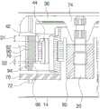
As shown in fig. 5 and 6, the cooling fan according to another embodiment of the present invention has the same structure as the cooling fan described in the above embodiment, and the magnet 90 has a structure different from the magnet 32 of the above embodiment.
The sensor force increasing portion of the other embodiment is a protrusion 94 that protrudes toward the lower side of the magnet to increase the length of the magnet 90, thereby increasing the magnetic field strength along the lower side of the magnet 90.
That is, the area of the magnet 90 is increased by projecting the lower portion of the magnet 90 in the lower direction, and the magnetic field strength in the lower direction of the magnet 90 is increased according to the increased area of the magnet 90, so that the hall sensor 72 mounted on the rear surface of the printed circuit board 70 can easily sense the magnetic field of the magnet 90.
Preferably, the magnet 90 of the present embodiment is formed of a Neodymium (ND) magnet. The neodymium magnet is made of sintered neodymium, iron, boron, or the like, and when the magnet 90 is sintered, the protrusion 94 is integrally formed with the magnet 90.
The thickness of the projection 94 is thinner than the thickness of the other portions of the magnet 90. That is, the inclined surface 96 is formed on the inner surface of the protrusion 90 so as to be thinner in the lower direction than the other portions of the magnet 90.
The interval D1 between the upper end of the magnet 90 and the upper end of the iron core 42 is greater than the interval D2 between the lower end of the magnet 90 and the lower end of the iron core 42. This is because the magnetic field intensity acting on the stator 40 at the upper portion of the magnet 90 is made larger than the magnetic field intensity acting on the stator 40 at the lower portion of the magnet 90, and the rotor 30 is prevented from coming off by suppressing the rotor 30 from moving in the upward direction when the rotor 30 rotates.
If the protrusion 94 is formed to protrude from the lower portion of the magnet 90, the length of the lower portion of the magnet 90 is longer than that of the upper portion, and the magnetic field intensity acting on the stator 40 is larger at the lower portion of the magnet 90 than at the upper portion of the magnet 90, so that the rotor 30 may be detached.
In the present invention, an inclined surface 96 is formed on the inner surface of the protruding portion 94 to reduce the thickness of the protruding portion 94 so that the area of the lower portion of the magnet 90 can be expanded while preventing the rotor 30 from being detached. That is, the magnetic field intensity generated in the protruding portion 94 is weakened in the inner direction affecting the stator, and is increased in the lower direction detectable by the hall sensor.
The inner surface of the protruding portion 94 can be formed in various forms such as a stepped form, which can be made thinner, in addition to the form of the inclined surface 96. The outer face of the protrusion 94 allows the magnetic field to leak in the outside direction of the protrusion 92 by the exposure of the non-back yoke 92, thereby improving the sensing performance of the hall sensor.
While the present invention has been illustrated and described with reference to the specific preferred embodiments, the present invention is not limited to the above-described embodiments, and various changes and modifications can be made by those skilled in the art to which the present invention pertains without departing from the technical spirit of the present invention.
Industrial applicability
The cooling fan of the present invention is applicable to a device for preventing overheating of an electronic apparatus, an automobile, a light emitting diode lighting lamp, or the like.