Vehicle and carriage chassis thereof
Technical Field
The invention relates to a vehicle and a carriage chassis thereof.
Background
The carriage of van transport vechicle in the existing market mainly has two kinds of structures of pure steel component and composite sheet combination formula, and the carriage chassis of these two kinds of structures all adopts the steel component usually to guarantee the structural strength that the carriage carried cargo. However, the steel member has a large mass, resulting in a heavy vehicle compartment as a whole. In order to meet the requirement of light weight, a manufacturer adjusts the mounting structure of the carriage, wherein aluminum section wrapping is installed at the corner connecting part of the adjacent side plates of the carriage to serve as a connecting piece, the aluminum section wrapping is usually fixed in a riveting mode, the wrapping is usually carried out by hands of workers in the mounting process, the position of the wrapping is usually guaranteed manually, and the mounting is inconvenient.
Disclosure of Invention
The invention aims to provide a carriage chassis, which solves the problem that the existing carriage edge covering needs workers to hold the edge covering with hands and manually ensure the position of the edge covering in the installation process, and is inconvenient to install; meanwhile, the invention also provides a vehicle for solving the problems.
In order to achieve the purpose, the technical scheme of the carriage underframe of the invention is as follows:
the carriage underframe comprises an underframe welding part, the underframe welding part comprises a bottom plate and supporting beams arranged at the lower part of the bottom plate, the edge of the underframe welding part is provided with a covered edge, the covered edge comprises a vertically arranged decorative plate and a horizontally arranged positioning plate positioned at the inner side of the decorative plate, at least one supporting beam is provided with a covered edge fixing part which extends to the edge of the underframe welding part and is fixedly connected with the covered edge, and an inserting gap for inserting the positioning plate is formed between the covered edge fixing part and the bottom plate; or, the edge-covering fixing part or the bottom plate is provided with an inserting gap for inserting the positioning plate.
When the installation is bordured, only need will bordure insert can guarantee the position of borduring in the grafting clearance that corresponds, then fixed with the fastener can, do not need the workman hand to bordure and guarantee the position of borduring, it is very convenient to install.
The inner side of the decorative plate is also provided with an auxiliary plate positioned below the positioning plate, the auxiliary plate is in positioning fit with the bottom surface of the edge covering fixing part, and the auxiliary plate, the positioning plate and the decorative plate enclose a positioning groove in positioning fit with the edge covering fixing part. The auxiliary plate is matched with the bottom surface of the binding fixing part in a positioning way, so that the rotational freedom degree of the binding can be limited, and the connection strength and the position limitation of the binding are effectively enhanced.
The top of the binding fixing part is provided with a step surface, the step surface comprises a bottom plate attaching part attached to the bottom plate and a bottom plate spacing part arranged at a distance from the bottom plate, and the splicing gap is positioned between the bottom plate spacing part and the bottom plate.
The edge-covering and the edge-covering fixing part are detachably connected. The edge cover can be conveniently detached and replaced when being collided or damaged.
The edge covering is connected with the edge covering fixing part through a threaded connecting piece. Simple structure and convenient disassembly.
The technical scheme of the vehicle is as follows:
the vehicle comprises a carriage, the carriage comprises a carriage underframe and a side plate connected to the carriage underframe, the carriage underframe comprises an underframe welding part, the underframe welding part comprises a bottom plate and a support beam arranged at the lower part of the bottom plate, the edge of the underframe welding part is provided with a covered edge, the covered edge comprises a vertically arranged decorative plate and a horizontally arranged positioning plate positioned at the inner side of the decorative plate, at least one support beam is provided with a covered edge fixing part which extends to the edge of the underframe welding part and is fixedly connected with the covered edge, and an insertion gap for the positioning plate to be inserted is formed between the covered edge fixing part; or, the edge-covering fixing part or the bottom plate is provided with an inserting gap for inserting the positioning plate.
When the installation is bordured, only need will bordure insert can guarantee the position of borduring in the grafting clearance that corresponds, then fixed with the fastener can, do not need the workman hand to bordure and guarantee the position of borduring, it is very convenient to install.
The inner side of the decorative plate is also provided with an auxiliary plate positioned below the positioning plate, the auxiliary plate is in positioning fit with the bottom surface of the edge covering fixing part, and the auxiliary plate, the positioning plate and the decorative plate enclose a positioning groove in positioning fit with the edge covering fixing part. The auxiliary plate is matched with the bottom surface of the binding fixing part in a positioning way, so that the rotational freedom degree of the binding can be limited, and the connection strength and the position limitation of the binding are effectively enhanced.
The top of the binding fixing part is provided with a step surface, the step surface comprises a bottom plate attaching part attached to the bottom plate and a bottom plate spacing part arranged at a distance from the bottom plate, and the splicing gap is positioned between the bottom plate spacing part and the bottom plate.
The edge-covering and the edge-covering fixing part are detachably connected. The edge cover can be conveniently detached and replaced when being collided or damaged.
The edge covering is connected with the edge covering fixing part through a threaded connecting piece. Simple structure and convenient disassembly.
Drawings
FIG. 1 is a front view of an embodiment of the inventive bed underframe;
FIG. 2 is a left side view of an embodiment of the inventive bed underframe;
FIG. 3 is a schematic illustration of the tipping of an embodiment of the car underframe of the present invention;
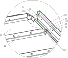
FIG. 4 is an enlarged view of FIG. 3 at P;
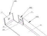
FIG. 5 is a schematic structural view of the cross beam of FIG. 3;
FIG. 6 is a schematic view of the left and right wrapping edges and the cross beam in FIG. 3 after the insertion;
FIG. 7 is an enlarged view of FIG. 6 at F;
in the figure: 1-welding a bottom frame; 11-a base plate; 12-a cross beam; 120-side mounting plate; 13-a central stiffening beam; 14-a stringer; 15-a front end stiffening beam; 16-a binding fixing part; 160-step surface; 1601-a backplane spacing section; 1602-a backplane attachment section; 17-a threaded hole; 21-front edge wrapping; 22-left wrapping; 23-right wrapping; 31-a decorative plate; 32-positioning plate; 33-an auxiliary plate; 34-a positioning groove; 4-insertion gaps; 51-countersunk head screws; 52-hexagon socket head flat round head screw.
Detailed Description
The following further describes embodiments of the present invention with reference to the drawings.
The specific embodiment of the carriage chassis comprises a chassis welding joint 1, wherein the chassis welding joint 1 comprises a bottom plate 11 and a supporting beam arranged at the lower part of the bottom plate 11, the supporting beam comprises a cross beam 12 extending along the front-back direction and a longitudinal beam 14 extending along the left-right direction, the edge of the chassis welding joint 1 is provided with a covered edge, and the covered edge comprises a front covered edge 21 arranged at the front side edge of the chassis welding joint 1, a left covered edge 22 arranged at the left side edge of the chassis welding joint 1 and a right covered edge 23 arranged at the right side edge of the chassis welding joint 1. Each edge has the same structure, and as shown in fig. 4, each edge includes a vertically arranged decorative plate 31 and a horizontally arranged positioning plate 32 located inside the decorative plate 31. The cross beam 12 close to the front end of the base frame welding joint 1, the cross beam 12 close to the rear end of the base frame welding joint 1 and each longitudinal beam 14 are provided with edge covering fixing parts 16 extending to the edge of the base frame welding joint 1, two ends of the cross beam 12 are respectively fixedly connected with a left edge covering 23 and a right edge covering 23 through the edge covering fixing parts 16, and the front end of each longitudinal beam 14 is fixedly connected with a front edge covering 21 through the edge covering fixing part 16. An insertion gap 4 for inserting the positioning plate 32 is formed between the binding fixing part 16 and the bottom plate 11. Specifically, as shown in fig. 5, a step surface 160 is provided on the top of the hemming fixing portion 16, the step surface 160 includes a bottom plate attaching portion 1602 attached to the bottom plate 11 and a bottom plate spacing portion 1601 disposed at a distance from the bottom plate 11, and the inserting gap 4 is located between the bottom plate spacing portion 1601 and the bottom plate 11. As shown in fig. 4 and 7, an auxiliary plate 33 is further provided on the inner side of the decorative plate 31 below the positioning plate 32, the auxiliary plate 33 is horizontally disposed and is positioned and engaged with the bottom surface of the hemming-fixing portion 16, and the auxiliary plate 33, the positioning plate 32 and the decorative plate 31 enclose a positioning groove 34 positioned and engaged with the hemming-fixing portion 16.
As shown in fig. 3, the bottom plate 11 is further provided with a reinforcing beam at the lower part thereof, the reinforcing beam comprises a front reinforcing beam 15 at the front end of the bottom plate 11 and a middle reinforcing beam 13 near the middle part of the bottom plate 11, the front reinforcing beam 15 and the middle reinforcing beam 13 both extend in the front-rear direction, and the middle reinforcing beam 13 is connected between two adjacent cross beams 12. The front end of the front end reinforcing beam 15 has a hemming fixing portion 16 extending to the edge of the underframe weld 1, and is fixedly connected with the front hemming 21 by the hemming fixing portion 16. The front end reinforcing beam 15 and the front flange 21 are connected in the same manner as the side member 14 and the front flange 21.
The positioning plates 32 of each edge cover are respectively inserted into the corresponding inserting gaps 4 and fixedly connected with the underframe welding 1 through countersunk screws 51, so that the upper surface of the bottom plate 11 is flat and has no protrusion. Threaded holes 17 are reserved at the two ends of the cross beam 12, the front end of the longitudinal beam 14 and the front end of the front end reinforcing beam 15, countersunk screw mounting holes are formed in each edge and correspond to the threaded holes 17, and the countersunk screws 51 are mounted in the countersunk screw mounting holes. When the edge cover is collided or damaged, the edge cover can be detached for replacement. In addition, as shown in fig. 2 and 4, when each of the rims is fixedly connected to the chassis base 1, in addition to the upper end thereof being fixed by the countersunk head screw 51, the side surface of each of the rims is fixedly connected to the rim fixing portion 16 by the hexagonal flat round head screw 52, so that the connection reliability between the rim and the rim fixing portion 16 is further ensured. Taking the connection between the beam 12 and the right wrapping 23 as an example, as shown in fig. 4 and 5, two ends of the beam 12 are provided with side mounting plates 120 which are vertically arranged, a threaded hole 17 is reserved on the side mounting plate 120, a decorative plate 31 of the right wrapping 23 is provided with an inner hexagon screw mounting hole corresponding to the threaded hole 17 on the side mounting plate 120, and an inner hexagon flat round head screw 52 is mounted in the inner hexagon screw mounting hole.
The chassis seam is wholly steel sheet material, guarantees that the carriage chassis has good structural strength, and each parcel limit is the aluminium alloy, has reduced carriage chassis weight to a certain extent, realizes the lightweight design under the prerequisite of guaranteeing structural strength.
In the production process of the carriage underframe, when the wrapping edges are installed after the welding processing of the underframe is finished, the positions of the wrapping edges can be ensured only by inserting the wrapping edges into the corresponding inserting gaps, and then the wrapping edges are fixed by using countersunk head screws and inner hexagonal flat round head screws, so that workers do not need to hold the wrapping edges to ensure the wrapping edge positions, and the installation is very convenient; when the edge cover is collided or damaged, the edge cover can be detached for replacement.
In the above embodiment, the inner side of the decorative plate is further provided with an auxiliary plate located below the positioning plate, the auxiliary plate is in positioning fit with the bottom surface of the edge-covering fixing part, and the auxiliary plate, the positioning plate and the decorative plate enclose a positioning groove in positioning fit with the edge-covering fixing part. In other embodiments, the auxiliary plate is not arranged, and the positioning plate and the decorative plate are used for positioning the edge covering.
In the above embodiment, the top of the fixing portion of the wrapping edge is provided with the step surface, the step surface comprises the bottom plate attaching portion attached to the bottom plate and the bottom plate spacing portion arranged at an interval with the bottom plate, and the insertion gap is located between the bottom plate spacing portion and the bottom plate. In other embodiments, the top of the edge-covering fixing part may also be a plane, a step surface may be provided at a position corresponding to the edge-covering fixing part on the lower portion of the base plate, the step surface includes an attaching part attached to the edge-covering fixing part and a spacing part spaced from the edge-covering fixing part, and the insertion gap is located between the spacing part and the edge-covering fixing part. Or the top of the binding fixing part is a plane which is attached to the bottom plate, and the binding fixing part is provided with an inserting gap for inserting the binding positioning plate. Or, an inserting gap for inserting the positioning plate of the edge covering is arranged on the bottom plate.
In the above embodiment, the edge covering is mainly connected with the edge covering fixing part through the positioning plate, the connecting piece adopts the countersunk head screw, and meanwhile, the decorative plate is also fixedly connected with the edge covering fixing part through the inner hexagonal flat round head screw so as to further enhance the connection reliability of the edge covering and the edge covering fixing part. In other embodiments, the edge cover can be connected with the edge cover fixing part only through the positioning plate, and the connecting piece can also adopt a bolt and be fastened by matching with a nut. The fixing part of the edge covering and the edge covering can also be riveted.
The invention also provides an embodiment of the vehicle, the vehicle comprises a carriage, the carriage comprises a carriage underframe and a side plate connected to the carriage underframe, the specific structure of the carriage underframe is described in each embodiment of the carriage underframe, and the detailed description is omitted here.