CN111237107A - Fuel supply system for reducing pressure pulsations in gaseous-fuelled internal combustion engines - Google Patents
Fuel supply system for reducing pressure pulsations in gaseous-fuelled internal combustion engines Download PDFInfo
- Publication number
- CN111237107A CN111237107A CN202010115243.5A CN202010115243A CN111237107A CN 111237107 A CN111237107 A CN 111237107A CN 202010115243 A CN202010115243 A CN 202010115243A CN 111237107 A CN111237107 A CN 111237107A
- Authority
- CN
- China
- Prior art keywords
- fuel
- gaseous fuel
- gaseous
- fluid flow
- fuel supply
- Prior art date
- Legal status (The legal status is an assumption and is not a legal conclusion. Google has not performed a legal analysis and makes no representation as to the accuracy of the status listed.)
- Granted
Links
- 239000000446 fuel Substances 0.000 claims 91
- 239000012530 fluid Substances 0.000 claims 18
- 238000002485 combustion reaction Methods 0.000 claims 14
- 239000007788 liquid Substances 0.000 claims 6
- 238000002347 injection Methods 0.000 claims 5
- 239000007924 injection Substances 0.000 claims 5
- 230000009977 dual effect Effects 0.000 claims 2
- 239000007789 gas Substances 0.000 claims 2
- VNWKTOKETHGBQD-UHFFFAOYSA-N methane Chemical compound C VNWKTOKETHGBQD-UHFFFAOYSA-N 0.000 claims 2
- 230000001419 dependent effect Effects 0.000 claims 1
- 239000003345 natural gas Substances 0.000 claims 1
- 230000010349 pulsation Effects 0.000 claims 1
Images


Classifications
-
- F—MECHANICAL ENGINEERING; LIGHTING; HEATING; WEAPONS; BLASTING
- F02—COMBUSTION ENGINES; HOT-GAS OR COMBUSTION-PRODUCT ENGINE PLANTS
- F02M—SUPPLYING COMBUSTION ENGINES IN GENERAL WITH COMBUSTIBLE MIXTURES OR CONSTITUENTS THEREOF
- F02M21/00—Apparatus for supplying engines with non-liquid fuels, e.g. gaseous fuels stored in liquid form
- F02M21/02—Apparatus for supplying engines with non-liquid fuels, e.g. gaseous fuels stored in liquid form for gaseous fuels
- F02M21/0218—Details on the gaseous fuel supply system, e.g. tanks, valves, pipes, pumps, rails, injectors or mixers
- F02M21/023—Valves; Pressure or flow regulators in the fuel supply or return system
- F02M21/0239—Pressure or flow regulators therefor
-
- F—MECHANICAL ENGINEERING; LIGHTING; HEATING; WEAPONS; BLASTING
- F02—COMBUSTION ENGINES; HOT-GAS OR COMBUSTION-PRODUCT ENGINE PLANTS
- F02D—CONTROLLING COMBUSTION ENGINES
- F02D19/00—Controlling engines characterised by their use of non-liquid fuels, pluralities of fuels, or non-fuel substances added to the combustible mixtures
- F02D19/06—Controlling engines characterised by their use of non-liquid fuels, pluralities of fuels, or non-fuel substances added to the combustible mixtures peculiar to engines working with pluralities of fuels, e.g. alternatively with light and heavy fuel oil, other than engines indifferent to the fuel consumed
- F02D19/0663—Details on the fuel supply system, e.g. tanks, valves, pipes, pumps, rails, injectors or mixers
- F02D19/0686—Injectors
- F02D19/0689—Injectors for in-cylinder direct injection
-
- F—MECHANICAL ENGINEERING; LIGHTING; HEATING; WEAPONS; BLASTING
- F02—COMBUSTION ENGINES; HOT-GAS OR COMBUSTION-PRODUCT ENGINE PLANTS
- F02D—CONTROLLING COMBUSTION ENGINES
- F02D19/00—Controlling engines characterised by their use of non-liquid fuels, pluralities of fuels, or non-fuel substances added to the combustible mixtures
- F02D19/06—Controlling engines characterised by their use of non-liquid fuels, pluralities of fuels, or non-fuel substances added to the combustible mixtures peculiar to engines working with pluralities of fuels, e.g. alternatively with light and heavy fuel oil, other than engines indifferent to the fuel consumed
- F02D19/0663—Details on the fuel supply system, e.g. tanks, valves, pipes, pumps, rails, injectors or mixers
- F02D19/0686—Injectors
- F02D19/0694—Injectors operating with a plurality of fuels
-
- F—MECHANICAL ENGINEERING; LIGHTING; HEATING; WEAPONS; BLASTING
- F02—COMBUSTION ENGINES; HOT-GAS OR COMBUSTION-PRODUCT ENGINE PLANTS
- F02D—CONTROLLING COMBUSTION ENGINES
- F02D19/00—Controlling engines characterised by their use of non-liquid fuels, pluralities of fuels, or non-fuel substances added to the combustible mixtures
- F02D19/06—Controlling engines characterised by their use of non-liquid fuels, pluralities of fuels, or non-fuel substances added to the combustible mixtures peculiar to engines working with pluralities of fuels, e.g. alternatively with light and heavy fuel oil, other than engines indifferent to the fuel consumed
- F02D19/08—Controlling engines characterised by their use of non-liquid fuels, pluralities of fuels, or non-fuel substances added to the combustible mixtures peculiar to engines working with pluralities of fuels, e.g. alternatively with light and heavy fuel oil, other than engines indifferent to the fuel consumed simultaneously using pluralities of fuels
- F02D19/10—Controlling engines characterised by their use of non-liquid fuels, pluralities of fuels, or non-fuel substances added to the combustible mixtures peculiar to engines working with pluralities of fuels, e.g. alternatively with light and heavy fuel oil, other than engines indifferent to the fuel consumed simultaneously using pluralities of fuels peculiar to compression-ignition engines in which the main fuel is gaseous
-
- F—MECHANICAL ENGINEERING; LIGHTING; HEATING; WEAPONS; BLASTING
- F02—COMBUSTION ENGINES; HOT-GAS OR COMBUSTION-PRODUCT ENGINE PLANTS
- F02M—SUPPLYING COMBUSTION ENGINES IN GENERAL WITH COMBUSTIBLE MIXTURES OR CONSTITUENTS THEREOF
- F02M43/00—Fuel-injection apparatus operating simultaneously on two or more fuels, or on a liquid fuel and another liquid, e.g. the other liquid being an anti-knock additive
- F02M43/04—Injectors peculiar thereto
-
- F—MECHANICAL ENGINEERING; LIGHTING; HEATING; WEAPONS; BLASTING
- F02—COMBUSTION ENGINES; HOT-GAS OR COMBUSTION-PRODUCT ENGINE PLANTS
- F02M—SUPPLYING COMBUSTION ENGINES IN GENERAL WITH COMBUSTIBLE MIXTURES OR CONSTITUENTS THEREOF
- F02M21/00—Apparatus for supplying engines with non-liquid fuels, e.g. gaseous fuels stored in liquid form
- F02M21/02—Apparatus for supplying engines with non-liquid fuels, e.g. gaseous fuels stored in liquid form for gaseous fuels
- F02M21/0218—Details on the gaseous fuel supply system, e.g. tanks, valves, pipes, pumps, rails, injectors or mixers
- F02M21/0248—Injectors
- F02M21/0257—Details of the valve closing elements, e.g. valve seats, stems or arrangement of flow passages
- F02M21/026—Lift valves, i.e. stem operated valves
- F02M21/0263—Inwardly opening single or multi nozzle valves, e.g. needle valves
-
- F—MECHANICAL ENGINEERING; LIGHTING; HEATING; WEAPONS; BLASTING
- F02—COMBUSTION ENGINES; HOT-GAS OR COMBUSTION-PRODUCT ENGINE PLANTS
- F02M—SUPPLYING COMBUSTION ENGINES IN GENERAL WITH COMBUSTIBLE MIXTURES OR CONSTITUENTS THEREOF
- F02M2200/00—Details of fuel-injection apparatus, not otherwise provided for
- F02M2200/31—Fuel-injection apparatus having hydraulic pressure fluctuations damping elements
- F02M2200/315—Fuel-injection apparatus having hydraulic pressure fluctuations damping elements for damping fuel pressure fluctuations
-
- Y—GENERAL TAGGING OF NEW TECHNOLOGICAL DEVELOPMENTS; GENERAL TAGGING OF CROSS-SECTIONAL TECHNOLOGIES SPANNING OVER SEVERAL SECTIONS OF THE IPC; TECHNICAL SUBJECTS COVERED BY FORMER USPC CROSS-REFERENCE ART COLLECTIONS [XRACs] AND DIGESTS
- Y02—TECHNOLOGIES OR APPLICATIONS FOR MITIGATION OR ADAPTATION AGAINST CLIMATE CHANGE
- Y02T—CLIMATE CHANGE MITIGATION TECHNOLOGIES RELATED TO TRANSPORTATION
- Y02T10/00—Road transport of goods or passengers
- Y02T10/10—Internal combustion engine [ICE] based vehicles
- Y02T10/30—Use of alternative fuels, e.g. biofuels
Landscapes
- Engineering & Computer Science (AREA)
- Chemical & Material Sciences (AREA)
- Combustion & Propulsion (AREA)
- Mechanical Engineering (AREA)
- General Engineering & Computer Science (AREA)
- Oil, Petroleum & Natural Gas (AREA)
- Chemical Kinetics & Catalysis (AREA)
- General Chemical & Material Sciences (AREA)
- Fuel-Injection Apparatus (AREA)
- Output Control And Ontrol Of Special Type Engine (AREA)
Abstract
一种用于气体燃料内燃机的燃料供应系统,包括:气体燃料供应管道;用于将气体燃料喷射到内燃机中的燃料喷射器,其具有第一机体以及喷嘴室;安置在气体燃料供应管道与预定容积的气体燃料流通道之间并且将其流体地连接起来的第二机体,气体燃料供应管道通过气体燃料流通道连接至喷嘴室,第二机体限定用于将气体燃料递送到喷嘴室的受限的流体流通道,其在气体燃料供应管道与喷嘴室之间具有最小的有效面积,其流体流通面积根据预定容积选择,以使气体燃料流通道内的压力脉动保持在预定压力范围内,同时使喷嘴室内的气体燃料压力保持在对于每个发动机运行条件喷射预定喷射脉冲宽度内的控制量的气体燃料所需的预定阈值之上。
A fuel supply system for a gaseous fuel internal combustion engine, comprising: a gaseous fuel supply pipe; a fuel injector for injecting gaseous fuel into the internal combustion engine, which has a first body and a nozzle chamber; a second body fluidly connecting between and fluidly connecting the gaseous fuel flow passages of the volume, the gaseous fuel supply conduits are connected to the nozzle chamber through the gaseous fuel flow passages, the second body defining a confinement for delivering the gaseous fuel to the nozzle chamber The fluid flow channel has the smallest effective area between the gaseous fuel supply pipe and the nozzle chamber, and its fluid flow area is selected according to the predetermined volume, so that the pressure pulsation in the gaseous fuel flow channel is maintained within the predetermined pressure range, while making the nozzle The gaseous fuel pressure in the chamber is maintained above a predetermined threshold required to inject a controlled amount of gaseous fuel within a predetermined injection pulse width for each engine operating condition.
Description
本申请是申请日为2015年12月11日、申请号为2015800759255、名称为“用于降低气体燃料内燃机中的压力脉动的装置”的发明专利申请的分案申请。This application is a divisional application for an invention patent application with an application date of December 11, 2015, an application number of 2015800759255, and the title of "device for reducing pressure pulsation in a gas-fueled internal combustion engine".
技术领域technical field
本公开内容涉及一种用于气体燃料内燃机的燃料供应系统,其包括机体,该机体限定受限的流体流通道以降低燃料喷射器喷嘴处的压力脉动。The present disclosure relates to a fuel supply system for a gaseous-fueled internal combustion engine that includes a block defining a restricted fluid flow passage to reduce pressure pulsation at a fuel injector nozzle.
背景技术Background technique
液体燃料(诸如柴油)以及最近的气体燃料已被用于燃料汽车发动机多年。所述气体燃料包括天然气、丙烷、氢气、甲烷、丁烷、乙烷或其混合物等。发动机燃料喷射系统通常包括多个燃料喷射器,所述多个燃料喷射器流体地连接至燃料供应管道。通常,在直接喷射系统的情况下,每个燃料喷射器位于发动机的气缸盖中形成的孔中,并且燃料供应管道(通常称为燃料轨道)可以位于气缸盖中形成的孔中或者可以是通过气缸盖中设置的孔与每个喷射器流体地连接的外部管。每个喷射器作为燃料阀操作,其打开和关闭,以分别用于将燃料喷射到每个发动机气缸的燃烧室中和用于停止燃料流进入燃烧室。燃料喷射器的这种打开和关闭在喷射器燃料入口处产生压力脉动,由于喷射事件之间的较短间隔,该压力脉动在喷射器关闭期间不能被抑制。这种压力脉动可能在喷射器喷嘴处产生燃料压力增加或压降,这在喷射事件期间影响喷射到燃烧室中的燃料量。这种压力脉动也可能从一个喷射器传递回燃料轨道并且通过该轨道传递到发动机的下一个燃料喷射器。此外,如果燃料轨道中的压力波动,则轨道中的压力脉动可以传递到燃料喷射器的入口并进一步传递到喷射器喷嘴。Liquid fuels, such as diesel, and more recently gaseous fuels have been used to fuel automotive engines for many years. The gaseous fuel includes natural gas, propane, hydrogen, methane, butane, ethane, or a mixture thereof, and the like. Engine fuel injection systems typically include a plurality of fuel injectors fluidly connected to a fuel supply conduit. Typically, in the case of a direct injection system, each fuel injector is located in a hole formed in the cylinder head of the engine, and the fuel supply conduit (often called the fuel rail) may be located in the hole formed in the cylinder head or may be through A hole provided in the cylinder head is fluidly connected to the outer tube of each injector. Each injector operates as a fuel valve that opens and closes for injecting fuel into the combustion chamber of each engine cylinder and for stopping fuel flow into the combustion chamber, respectively. This opening and closing of the fuel injector creates a pressure pulsation at the injector fuel inlet that cannot be suppressed during injector closing due to the short interval between injection events. Such pressure pulsations may create a fuel pressure increase or pressure drop at the injector nozzle, which affects the amount of fuel injected into the combustion chamber during an injection event. This pressure pulsation may also be transmitted from one injector back to the fuel rail and through the rail to the next fuel injector of the engine. Furthermore, if the pressure in the fuel rail fluctuates, the pressure pulsation in the rail can be transmitted to the inlet of the fuel injector and further to the injector nozzle.
过去,上述问题已经通过将衬套结合在向柴油发动机的喷射器供应燃料的燃料轨道中来解决,例如美国专利号7,516,734中所描述的,这种衬套提供了限制从燃料轨道到喷射器的燃料流的孔口,由此抑制了将燃料轨道连接至燃料喷射器的燃料通道中的压力脉动。现有技术中已经公开了若干其他类似的方案,以解决供应到内燃机的喷射器的传统液体燃料(诸如柴油燃料或汽油)中的压力脉动的问题。由于气体燃料的物理成分(其倾向于延长压力振荡),所以在气体燃料中,由喷射器的打开和关闭造成的压力脉动表现为与液体燃料不同。In the past, the above problems have been addressed by incorporating bushings in the fuel rails supplying fuel to the injectors of diesel engines, such as described in US Pat. No. 7,516,734, such bushings provide limited access to the injectors from the fuel rails. The orifices for fuel flow, thereby suppressing pressure pulsations in the fuel passages connecting the fuel rail to the fuel injectors. Several other similar solutions have been disclosed in the prior art to address the problem of pressure pulsations in conventional liquid fuels, such as diesel fuel or gasoline, supplied to the injectors of internal combustion engines. Due to the physical composition of gaseous fuels, which tend to prolong pressure oscillations, in gaseous fuels the pressure pulsations caused by the opening and closing of injectors behave differently than in liquid fuels.
在其他变型中,至少一个抑制元件设置在燃料喷射器的开口中,来自燃料轨道的燃料流过燃料喷射器的开口,诸如美国专利7,059,548中所描述的。In other variations, at least one suppression element is disposed in an opening of a fuel injector through which fuel from the fuel rail flows, such as described in US Pat. No. 7,059,548.
在现有技术中提出的设计方案没有考虑如下问题:确定脉动抑制孔口相对于喷射器喷嘴的位置,用于控制燃料轨道和燃料喷射器之间的压力脉动的抑制以及用于在燃料喷射到燃烧室中之前控制喷嘴室内的燃料压力。对于通过双燃料喷射阀将气体燃料和液体燃料直接喷射进燃烧室中的双燃料发动机来说,这个问题变得更加重要,该双燃料喷射阀包括具有用于单独且独立地喷射液体燃料和气体燃料的同心针的双针组件,例如在申请人的美国专利7,124,959中所描述的。在这种燃料喷射器中,在喷射器的机体内在液体燃料压力和气体燃料压力之间必须保持预定的偏差(bias),其中液体燃料压力高于气体燃料压力,以防止气体燃料泄漏到液体燃料中。气体燃料由于其物理状态可以更容易泄漏通过燃料喷射器内的密封装置,并且可能泄漏到液体燃料中,或者如果其从气体燃料通道泄漏到燃料喷射器内的液压流体控制室中,可能损害阀致动器的液压功能。The designs proposed in the prior art do not take into account the problems of determining the position of the pulsation suppression orifice relative to the injector nozzle, for controlling the suppression of pressure pulsations between the fuel rail and the fuel injector, and for The fuel pressure in the nozzle chamber was previously controlled in the combustion chamber. This problem becomes even more important for dual fuel engines where gaseous and liquid fuels are injected directly into the combustion chamber via a dual fuel injection valve that includes a system for injecting liquid and gas separately and independently A dual needle assembly of concentric needles for fuel, such as described in applicant's US Pat. No. 7,124,959. In such fuel injectors, a predetermined bias must be maintained within the body of the injector between the liquid fuel pressure and the gaseous fuel pressure, where the liquid fuel pressure is higher than the gaseous fuel pressure, to prevent leakage of the gaseous fuel into the liquid in fuel. Gaseous fuel can leak through seals within the fuel injector more easily due to its physical state and may leak into the liquid fuel, or if it leaks from the gaseous fuel passage into the hydraulic fluid control chamber within the fuel injector, it may damage the valve Hydraulic function of the actuator.
因此,需要一种解决方案来对抑制燃料喷射器喷嘴处的压力脉动更好地进行控制,同时控制燃料轨道和燃料喷射器喷嘴之间的压降,以防止泄漏并且在其被喷射到燃烧室中之前控制喷射器喷嘴处的燃料压力。Therefore, a solution is needed to better control the suppression of pressure pulsations at the fuel injector nozzle, while controlling the pressure drop between the fuel rail and the fuel injector nozzle to prevent leakage and before it is injected into the combustion chamber Controls the fuel pressure at the injector nozzles prior to .
发明内容SUMMARY OF THE INVENTION
一种改进的机体,在燃料供应系统中限定受限的流体流通道以用于将气体燃料递送至内燃机。所述机体形成为安置在气体燃料供应管道和气体燃料流通道之间并将所述气体燃料供应管道和所述气体燃料流通道流体地连接,所述气体燃料流通道在所述受限的流体流通道与燃料喷射器的喷嘴室(所述气体燃料从该喷嘴室喷射到所述内燃机中)之间限定预定容积。所述受限的流体流通道在所述气体燃料供应管道与所述喷嘴室之间具有最小的有效流通面积。所述受限的流体流通道位于距所述燃料喷射器内的喷射阀密封件预定距离处。所述预定距离是根据所述气体燃料中的声速和所述燃料喷射器的打开时间计算的。An improved block defining restricted fluid flow passages in a fuel supply system for delivering gaseous fuel to an internal combustion engine. The body is formed to be positioned between and fluidly connect a gaseous fuel supply conduit and a gaseous fuel flow passage, the gaseous fuel flow passage being in the confined fluid A predetermined volume is defined between the flow passage and a nozzle chamber of a fuel injector from which the gaseous fuel is injected into the internal combustion engine. The restricted fluid flow passage has the smallest effective flow area between the gaseous fuel supply conduit and the nozzle chamber. The restricted fluid flow passage is located at a predetermined distance from an injection valve seal within the fuel injector. The predetermined distance is calculated based on the speed of sound in the gaseous fuel and the opening time of the fuel injector.
所述声速可以根据所述燃料供应系统采用的最大气体燃料压力确定,并且所述打开时间是用于所述内燃机的所述燃料喷射器的最大打开时间。在示例性实施例中,所述预定距离至少等于由所述气体燃料中的声速和所述燃料喷射器的所述打开时间的乘积所确定的距离。在另一示例性实施例中,所述预定距离至少等于由所述气体燃料中的声速和所述燃料喷射器的所述打开时间的乘积所确定的距离的一半。The speed of sound may be determined from the maximum gaseous fuel pressure employed by the fuel supply system, and the opening time is the maximum opening time of the fuel injector for the internal combustion engine. In an exemplary embodiment, the predetermined distance is at least equal to a distance determined by the product of the speed of sound in the gaseous fuel and the opening time of the fuel injector. In another exemplary embodiment, the predetermined distance is at least equal to half a distance determined by the product of the speed of sound in the gaseous fuel and the opening time of the fuel injector.
在示例性实施例中,根据所述预定容积选择所述受限的流体流通道的流体流通面积,以使所述气体燃料流通道内的压力脉动保持在预定压力范围内,同时使所述喷嘴室内的气体燃料压力保持在对于每个发动机运行条件喷射预定喷射脉冲宽度内的控制量的气体燃料所需的预定阈值之上。In an exemplary embodiment, the fluid flow area of the restricted fluid flow passage is selected based on the predetermined volume to maintain pressure pulsations within the gaseous fuel flow passage within a predetermined pressure range while keeping the nozzle chamber The gaseous fuel pressure is maintained above a predetermined threshold required to inject a controlled amount of gaseous fuel within a predetermined injection pulse width for each engine operating condition.
一种用于气体燃料内燃机的改进的燃料供应系统。具有气体燃料供应管道和用于将气体燃料喷射到所述内燃机中的燃料喷射器。所述燃料喷射器具有包括入口的第一机体,以及喷嘴室,所述喷嘴室流体地连接至所述入口并且所述气体燃料从所述喷嘴室喷射到所述内燃机中。所述燃料喷射器具有针(needle,阀针)和座,当所述针抵靠(abut,抵靠)所述座时,形成喷射阀。具有第二机体,所述第二机体形成为安置在所述气体燃料供应管道与预定容积的气体燃料流通道之间并且将所述气体燃料供应管道和所述气体燃料流通道流体地连接,所述气体燃料供应管道通过所述气体燃料流通道连接至所述喷嘴室。所述第二机体限定受限的流体流通道以用于将所述气体燃料递送到所述喷嘴室。所述受限的流体流通道在所述气体燃料供应管道与所述喷嘴室之间具有最小的有效面积。所述受限的流体流通道位于距所述燃料喷射器内的喷射阀密封件预定距离处。所述预定距离是根据所述气体燃料中的声速和所述燃料喷射器的打开时间计算的。An improved fuel supply system for a gaseous fuel internal combustion engine. There is a gaseous fuel supply line and a fuel injector for injecting the gaseous fuel into the internal combustion engine. The fuel injector has a first body including an inlet, and a nozzle chamber fluidly connected to the inlet and from which the gaseous fuel is injected into the internal combustion engine. The fuel injector has a needle (needle) and a seat which, when the needle abuts against the seat, forms an injection valve. having a second body formed to be positioned between the gaseous fuel supply conduit and the gaseous fuel flow passage of a predetermined volume and to fluidly connect the gaseous fuel supply conduit and the gaseous fuel flow passage, the The gaseous fuel supply conduit is connected to the nozzle chamber through the gaseous fuel flow passage. The second body defines a restricted fluid flow passage for delivering the gaseous fuel to the nozzle chamber. The restricted fluid flow passage has the smallest effective area between the gaseous fuel supply conduit and the nozzle chamber. The restricted fluid flow passage is located at a predetermined distance from an injection valve seal within the fuel injector. The predetermined distance is calculated based on the speed of sound in the gaseous fuel and the opening time of the fuel injector.
一种限制包括燃料喷射器的气体燃料内燃机的燃料供应系统内的压力脉动的改进方法。所述燃料喷射器具有喷射阀,并且所述喷射阀具有喷射阀密封件。所述方法包括:将受限的流体流通道定位在气体燃料供应管道与所述喷射阀密封件之间。所述受限的流体流通道在所述气体燃料供应管道与所述喷射阀密封件之间具有最小的有效面积。所述受限的流体流通道位于距所述喷射阀密封件预定距离处。所述预定距离是根据所述气体燃料中的声速和所述燃料喷射器的打开时间计算的。An improved method of limiting pressure pulsations within a fuel supply system of a gaseous fuel internal combustion engine including a fuel injector. The fuel injector has an injection valve, and the injection valve has an injection valve seal. The method includes positioning a restricted fluid flow passage between a gaseous fuel supply conduit and the injection valve seal. The restricted fluid flow passage has the smallest effective area between the gaseous fuel supply conduit and the injection valve seal. The restricted fluid flow passage is located at a predetermined distance from the injection valve seal. The predetermined distance is calculated based on the speed of sound in the gaseous fuel and the opening time of the fuel injector.
所述方法还可以包括:根据所述燃料供应系统的最大气体燃料压力确定所述声速;以及将所述打开时间确定为所述气体燃料内燃机采用的所述燃料喷射器的最大打开时间。在示例性实施例中,所述方法还包括:在关闭位置与打开位置之间致动所述燃料喷射器,从而打开所述喷射阀,借此在气体燃料流过所述喷射阀时产生朝向所述受限的流体流通道行进的压力波;以及在所述打开位置与所述关闭位置之间致动所述燃料喷射器,使得在所述压力波到达所述受限的流体流通道之时或之前关闭所述喷射阀。在另一示例性实施例中,所述方法还包括:在关闭位置与打开位置之间致动所述燃料喷射器,从而打开所述喷射阀,借此在气体燃料流出所述燃料喷射器时产生朝向所述受限的流体流通道行进的压力波;以及在所述打开位置与所述关闭位置之间致动所述燃料喷射器,使得在所述压力波被所述受限的流体流通道反射后基本上返回到其起点之前或之时关闭所述喷射阀。The method may further include: determining the speed of sound based on a maximum gaseous fuel pressure of the fuel supply system; and determining the opening time as a maximum opening time of the fuel injector employed by the gaseous fuel internal combustion engine. In an exemplary embodiment, the method further includes actuating the fuel injector between a closed position and an open position, thereby opening the injection valve, thereby creating a direction of flow of gaseous fuel through the injection valve a pressure wave traveling through the restricted fluid flow passage; and actuating the fuel injector between the open position and the closed position such that before the pressure wave reaches the restricted fluid flow passage Close the injection valve on or before. In another exemplary embodiment, the method further includes actuating the fuel injector between a closed position and an open position, thereby opening the injection valve, whereby when gaseous fuel flows out of the fuel injector generating a pressure wave traveling toward the restricted fluid flow passage; and actuating the fuel injector between the open position and the closed position such that the pressure wave is circulated by the restricted fluid The injection valve is closed before or when the track returns substantially to its starting point after reflection.
附图说明Description of drawings
图1是用于气体燃料内燃机的本燃料供应系统的示意图。FIG. 1 is a schematic diagram of the present fuel supply system for a gaseous fuel internal combustion engine.
图2是用于气体燃料内燃机的本燃料供应系统的第二实施例的示意图。FIG. 2 is a schematic diagram of a second embodiment of the present fuel supply system for a gaseous fuel internal combustion engine.
图3示出了将不具有受限的流体流通道的燃料供应系统的喷射室内的模拟气体燃料压力变化与具有不同尺寸的受限的流体流通道的燃料供应系统的模拟气体燃料压力进行比较的曲线图。Figure 3 shows a comparison of simulated gaseous fuel pressure changes within the injection chamber of a fuel supply system without restricted fluid flow passages to simulated gaseous fuel pressures of fuel supply systems with restricted fluid flow passages of different sizes Graph.
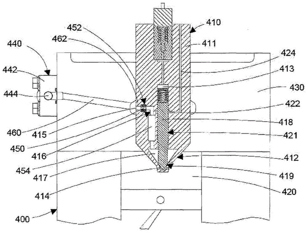
图4是用于双燃料内燃机的本燃料供应系统的另一实施例的示意图。Figure 4 is a schematic diagram of another embodiment of the present fuel supply system for a dual fuel internal combustion engine.
图5示出了图示了与不具有受限的流体流通道的双燃料内燃机的燃料供应系统的柴油燃料供应压力相比,喷嘴室内的气体燃料压力变化的模拟结果的曲线图。FIG. 5 shows a graph illustrating simulation results of gaseous fuel pressure changes in the nozzle chamber compared to the diesel fuel supply pressure of the fuel supply system of a dual fuel internal combustion engine without restricted fluid flow passages.
图6示出了图示了与类似于图4所示的具有受限的流体流通道的燃料供应系统的柴油燃料供应压力相比,喷嘴室内的气体燃料压力变化的模拟结果的曲线图。FIG. 6 shows a graph illustrating simulation results of gaseous fuel pressure variation within the nozzle chamber compared to the diesel fuel supply pressure of a fuel supply system similar to that shown in FIG. 4 with restricted fluid flow passages.
图7是带有六个气缸的包括本燃料供应系统的另一实施例的双燃料内燃机的示意图。7 is a schematic diagram of a dual fuel internal combustion engine with six cylinders including another embodiment of the present fuel supply system.
具体实施方式Detailed ways
图1示意性地示出了用于气体燃料内燃机的具有外部气体供应管道140(也称为气体燃料轨道)的本燃料供应系统。燃料供应系统包括用于将气体燃料喷射到发动机气缸100的燃烧室120中的燃料喷射器110。燃料喷射器110具有机体111,该机体包括:喷嘴112,设置有多个喷射孔114,燃料通过喷射孔喷射到燃烧室120中;入口115,流体地连接至气体燃料供应管道;以及内部燃料通道116,用于将燃料入口115流体地连接至燃料喷射器机体内的喷嘴室117。燃料喷射器还包括针118,该针可以从其座119被提起以打开燃料喷射器,并且允许燃料从喷嘴室117通过燃料喷射孔114喷射到燃烧室120中。当喷射器关闭时,针118位于其座119中,形成停止燃料喷射的喷射阀密封件。如图1所示,针118可以由液压致动器致动,更具体地,在由发动机控制器控制的液压致动器的液压控制室113中的液压流体压力的致动下,针118在燃料喷射器的机体111内部在针镗孔121内移动。为了避免从喷嘴室117到液压控制室113的任何气体燃料泄漏,在针与喷射器的机体中的针镗孔之间设置了流体密封件122。密封流体通过密封流体通道124供应到密封件。此外,为了防止任何进一步的泄漏,针118与针镗孔121在液压控制室113与喷嘴室117之间匹配配合。Figure 1 schematically shows the present fuel supply system with an external gas supply conduit 140 (also referred to as a gaseous fuel rail) for a gaseous fuel internal combustion engine. The fuel supply system includes
在图1所示的实施例中,燃料喷射器安装在气缸盖130中,并且燃料直接喷射到燃烧室120中。气体燃料从气体燃料供应管道140供应到燃料喷射器110,该气体燃料供应管道安装在气缸盖130上且包括机体142和气体燃料供应通道144,燃料流过该气体燃料供应通道。燃料通过受限的流体流通道150(即抑制孔口)和气体燃料流通道160从气体燃料供应管道的气体燃料供应通道144供应到喷嘴室117。气体燃料流通道160包括:气缸盖130中的第一燃料流通道162,燃料通过该第一燃料流通道从气体燃料供应管道144供应到喷射器入口115;和喷射器的机体内的内部燃料通道116,燃料通过该内部燃料通道从喷射器入口115供应到喷嘴室117。气体燃料流通道160将受限的流体流通道150流体地连接至喷嘴室117。In the embodiment shown in FIG. 1 , fuel injectors are mounted in
当气体燃料从气体燃料供应管道144供应到喷嘴室117时,来自气体燃料供应管道的压力脉动可以传递到燃料喷射器入口并且向下游传递到喷嘴室117。类似地,喷嘴室117中由喷射器的打开和关闭造成的压力脉动可以传递回到气体燃料供应管道,增强气体燃料供应管道中的脉动。气体燃料流通道内和喷嘴室内的这种压力脉动可以在喷射事件期间,更具体地,在由发动机控制器根据发动机运行条件控制的预定喷射脉冲宽度内,导致在燃烧室中喷射的燃料量的变化。此外,这种压力脉动可以导致喷嘴室117中的压力变得高于密封流体的压力或液压控制室113中的液压流体的压力。在这种情况下,气体燃料可通过匹配配合泄漏到密封流体和/或液压流体中,这是不期望的。因此,需要将喷嘴室117内的压力脉动的大小限制在预定限度内。When gaseous fuel is supplied from the gaseous
在本公开内容中,受限的流体流通道150以及受限的流体流通道150与燃料喷射器入口115之间的第一燃料流通道162的容积的尺寸被设计成降低气体燃料流通道160内(以及隐含地喷嘴室117内)的压力脉动。计算第一燃料流通道162的容积以及隐含地气体燃料流通道160(该气体燃料流通道包括第一燃料流通道162)的容积,以降低喷射器入口处和喷嘴室内的压力脉动,并且根据第一燃料流通道162的预定(计算的)容积并且隐含地根据整个气体燃料流通道160的容积选择受限的流体流通道150的流体流通面积,以将气体燃料流通道160内和喷嘴室117内的压力脉动保持在预定压力范围内,同时将喷嘴室内的气体燃料压力保持在对于每个发动机运行条件喷射预定喷射脉冲宽度内的控制量的气体燃料所需的预定阈值之上。In the present disclosure, the restricted
通常,通过减少在喷射时看到的燃料喷射器的入口压力变化的范围来提高喷射精确度。由于燃料喷射器内的被传递到燃料轨道的压力波的产生(由于燃料喷射的脉动性质),喷射器入口压力不是恒定的。燃料喷射器在打开时在喷射阀处产生较低的压力波,并且在关闭时产生较高的压力波。这些压力波起始于喷射阀处,并且最初向上游行进。为了实现看到的喷射器的入口压力变化范围的减小,将燃料喷射器与燃料轨道隔离是有用的,使得在喷射事件期间产生的压力波不被传递到燃料轨道以及因此不被传递到其他喷射器。就孔口的尺寸(即,受限的流体流通道的尺寸)而言,这种隔离存在限制。孔口不能太小,因为这会减少喷射事件期间通过喷射器的流。孔口相对于喷射阀(更具体地,相对于喷射阀密封件)的定位也是重要的。当孔口离喷射阀密封件足够远时,在喷射事件期间,孔口尺寸将对通过喷射器的流没有影响,因此当喷射阀打开时(即,在喷射事件期间),不存在通过孔口的燃料流。孔口可以放置在一定距离处,使得当喷射器关闭时,燃料流正要开始通过孔口。那么,孔口尺寸的唯一影响是,如果孔口太小,则其在喷射事件之间不能“再填充”孔口和喷射阀密封件之间的容积。在示例性实施例中,受限的流体流通道150位于距燃料喷射器110的喷射阀密封件预定距离处,使得在喷射事件期间不存在通过通道150的流。当打开喷射阀时产生的低压波到达通道时,流开始通过受限的流体流通道150。通道150和喷射阀之间的压力波以声速行进,并且预定距离可以至少等于根据等式1计算的值,其中D为预定距离(以米计),SOS为通过喷射阀和通道150之间的气体燃料的声速(以米/秒计),并且PW为喷射事件的脉冲宽度(以秒计),本文也称为打开时间。In general, injection accuracy is improved by reducing the range of changes in the inlet pressure of the fuel injector seen at the time of injection. Injector inlet pressure is not constant due to the generation of pressure waves within the fuel injector that are transmitted to the fuel rail (due to the pulsatile nature of fuel injection). The fuel injector produces a lower pressure wave at the injection valve when it is open and a higher pressure wave when it is closed. These pressure waves start at the injection valve and initially travel upstream. In order to achieve the reduction in the seen range of inlet pressure variation of the injector, it is useful to isolate the fuel injector from the fuel rail so that pressure waves generated during an injection event are not transmitted to the fuel rail and thus other injector. There are limitations to this isolation in terms of the size of the orifice (ie, the size of the restricted fluid flow channel). The orifice cannot be too small as this will reduce the flow through the injector during the injection event. The positioning of the orifice relative to the injection valve (more specifically, to the injection valve seal) is also important. When the orifice is far enough from the injection valve seal, the orifice size will have no effect on the flow through the injector during the injection event, so there is no flow through the orifice when the injection valve is open (ie, during the injection event) fuel flow. The orifice may be placed at a distance such that when the injector is closed, fuel flow is about to begin through the orifice. The only effect of orifice size, then, is that if the orifice is too small, it cannot "refill" the volume between the orifice and the injection valve seal between injection events. In the exemplary embodiment, restricted
D=SOS*PW 等式1D=SOS*
通过气体燃料的声速与气体燃料压力直接相关,并且随着压力增加而增加。在示例性实施例中,预定距离在气体燃料压力等于最大气体燃料压力并且脉冲宽度等于发动机100采用的最大脉冲宽度时根据等式1计算,由此有效地消除在此发动机运行条件和任何其他发动机运行条件下在喷射事件期间孔口的影响。通常,在最大发动机负载条件下采用最大气体燃料压力和最大脉冲宽度。The speed of sound through the gaseous fuel is directly related to the gaseous fuel pressure and increases as the pressure increases. In the exemplary embodiment, the predetermined distance is calculated according to
在另一示例性实施例中,预定距离可以至少等于根据下面的等式2计算的距离。当在喷射事件期间产生的低压波(波谷)到达受限的流体流通道150时,其被反射为高压波(波峰),开始朝向喷射阀返回。只要喷射阀在波峰波到达低压波前部的起始位置(在喷射阀密封件附近)之前关闭,则喷射的燃料量将基本上不受燃料喷射器内的压力波的影响,即使由于当喷射阀打开时低压波产生而导致气体燃料流已经开始通过受限的流体流通道150。类似于等式1,可以使用在最大发动机负载条件下确定的变量的参数值来计算等式2。In another exemplary embodiment, the predetermined distance may be at least equal to the distance calculated according to Equation 2 below. When the low pressure wave (trough) generated during the injection event reaches the restricted

图2是用于气体燃料内燃机的本燃料供应系统的第二实施例的示意图。该实施例的许多部件等同于图1所示的实施例的相同部件,并且相同部件由相同的附图标记标识。在本公开内容中,在每个实施例中,相同编号的部件以基本上相同的方式起作用。因此,如果已经相对于图1所示的第一实施例对相同部件进行了描述,则这里不会结合图2赘述这种部件的目的和功能。FIG. 2 is a schematic diagram of a second embodiment of the present fuel supply system for a gaseous fuel internal combustion engine. Many components of this embodiment are identical to the same components of the embodiment shown in FIG. 1 and the same components are identified by the same reference numerals. In this disclosure, like-numbered components function in substantially the same manner in each embodiment. Therefore, if the same components have been described with respect to the first embodiment shown in FIG. 1 , the purpose and function of such components will not be repeated here in connection with FIG. 2 .
图2所示的实施例与图1所示的实施例之间的区别在于,在该第二实施例中,受限的流体流通道未整体形成在燃料供应管道的机体内。替代地,单独的机体452被放置在喷射器机体411内且位于气体燃料供应管道440和喷嘴室417之间,并且机体452设置有受限的流体流通道450。在该实施例中,气体燃料流通道460是设置有扩大部分454的内部燃料通道416的一部分,气体燃料流通道将受限的流体流通道450流体地连接至喷嘴室417。计算受限的流体流通道与喷嘴室之间的气体燃料流通道460的容积,以降低喷嘴室417内的压力脉动。根据该气体燃料流通道的容积选择受限的流体流通道450的流体流通面积,以将内部燃料通道416和喷嘴室417内的压力脉动保持在预定压力范围内,同时将喷嘴室内的气体燃料压力保持在对于每个发动机运行条件喷射预定喷射脉冲宽度内的控制量的气体燃料所需的预定阈值之上。在一些实施例中,机体452可以整体形成在喷射器机体411中。受限的流体流通道450位于距喷射阀密封件预定距离处(如图1的实施例中所限定的),当针418抵靠座419时形成所述喷射阀密封件。在所示的实施例中,示出了内部燃料流通道416将受限的流体流通道450在直接路径中与喷嘴室417连接,在其他实施例中,通道416可以包括多个部段,其在受限的流体流通道和喷嘴室之间形成非直接的路径,使得受限的流体流通道位于距喷射阀密封件预定距离处。在示例性实施例中,可以存在串联连接的多个并排的流体通道部段,如扩大部分454,使得受限的流体流通道450和喷嘴室417之间的路径来回往复。The difference between the embodiment shown in Figure 2 and the embodiment shown in Figure 1 is that, in this second embodiment, the restricted fluid flow passages are not integrally formed within the body of the fuel supply conduit. Alternatively, a
在不同尺寸的抑制孔口上进行的模拟已经表明,通过减小受限的流体流通道的尺寸(以及隐含地受限的流体流通道的流通面积)来降低喷射器的喷嘴室内的压力脉动,如图3所示。与燃料供应系统中不存在受限的流体流通道时的喷嘴室内的压力脉动相比,对于包括分别具有3mm和2mm的受限的流体流通道的燃料系统而言,在打开喷射器之前和将喷射器关闭之后,喷射器的喷嘴室内的压力脉动降低。更具体地,观察到,对于具有3mm直径的抑制孔口的燃料供应系统而言,在燃料喷射开始(SOI)之前,喷嘴室内的燃料压力脉动的最大峰谷量值“A”小于不具有抑制孔口的燃料供应系统的燃料压力脉动的最大峰谷量值“B”,并且同时其大于具有2mm的抑制孔口的燃料供应系统的燃料压力脉动的最大峰谷量值“C”。如果压力脉动的最大峰谷量值大于预定范围,则喷射开始时喷嘴室内的压力可变化的超出预定的可接受的极限,并且这导致喷射到燃烧室中的燃料量的变化太大。这意味着,为了减少喷射事件期间喷射到燃烧室中的燃料量的变化,喷射事件之前喷嘴室内的平均压力优选地保持在预定范围内。图3中绘出的数据证明,如果没有被抑制,压力脉动可以影响发动机的性能。模拟结果已经表明,对该特定模拟发动机,对于分别具有3mm和2mm直径的抑制孔口的燃料供应系统而言,喷嘴室内的平均压力在预定的可接受范围Pacc内,而对于不具有抑制孔口的燃料系统而言,平均压力在预定范围之外。本公开内容中的平均压力被解释为在两个喷射事件之间在喷嘴室内测得的平均压力。在同一发动机上进行的模拟也已经表明,在喷射事件期间喷嘴室内的压降根据受限的流体流通道的尺寸而变化,更具体地,对于具有较小直径的受限的流体流通道而言,压降增加。如图3所示,在喷射事件期间,直径为2mm的受限的流体流通道的压降“D”大于直径为3mm的受限的流体流通道的压降“E”。这本身并不奇怪,但是它表明在选择受限的流体流通道的尺寸上的取舍,以在抑制和管理压降之间进行平衡,使得燃料喷射器喷嘴中的最终压力在对于每个发动机运行条件喷射预定喷射脉冲宽度内的所需量的燃料所需的最小压力之上。Simulations on different sized suppression orifices have shown that pressure pulsations in the nozzle chamber of the injector are reduced by reducing the size of the restricted fluid flow channel (and implicitly the flow area of the restricted fluid flow channel), As shown in Figure 3. Compared to the pressure pulsation in the nozzle chamber without the restricted fluid flow passage in the fuel supply system, for the fuel system including the restricted fluid flow passages of 3 mm and 2 mm, respectively, before and after opening the injector. After the ejector is closed, the pressure pulsation in the nozzle chamber of the ejector is reduced. More specifically, it was observed that for a fuel supply system with a 3 mm diameter suppression orifice, the maximum peak-to-valley magnitude "A" of the fuel pressure pulsation in the nozzle chamber prior to the start of fuel injection (SOI) was less than without suppression. The maximum peak-to-valley magnitude "B" of the fuel pressure pulsation of the orifice fuel supply system is at the same time greater than the maximum peak-to-valley magnitude "C" of the fuel pressure pulsation of the fuel supply system with the 2 mm suppression orifice. If the maximum peak-to-valley magnitude of the pressure pulsation is greater than a predetermined range, the pressure in the nozzle chamber at the start of injection may vary beyond predetermined acceptable limits, and this results in too much variation in the amount of fuel injected into the combustion chamber. This means that, in order to reduce variations in the amount of fuel injected into the combustion chamber during an injection event, the average pressure in the nozzle chamber prior to the injection event is preferably maintained within a predetermined range. The data plotted in Figure 3 demonstrate that, if not suppressed, pressure pulsations can affect engine performance. The simulation results have shown that, for this particular simulated engine, the average pressure in the nozzle chamber is within a predetermined acceptable range Pacc for the fuel supply system with 3mm and 2mm diameter suppression orifices, respectively, while for the fuel supply system with no suppression orifice For the fuel system of the port, the average pressure is outside the predetermined range. Average pressure in this disclosure is interpreted as the average pressure measured in the nozzle chamber between two injection events. Simulations performed on the same engine have also shown that the pressure drop in the nozzle chamber during an injection event varies according to the size of the restricted fluid flow passage, more specifically for restricted fluid flow passages with smaller diameters , the pressure drop increases. As shown in Figure 3, the pressure drop "D" for the 2 mm diameter restricted fluid flow channel is greater than the pressure drop "E" for the 3 mm diameter restricted fluid flow channel during the injection event. This is not surprising in itself, but it suggests a trade-off in choosing the size of the restricted fluid flow passages to balance between suppressing and managing pressure drop so that the final pressure in the fuel injector nozzle is the same for each engine operation Conditioning is above the minimum pressure required to inject a desired amount of fuel within a predetermined injection pulse width.
因此,基于模拟结果,受限的流体流通道的流通面积优选地选择为降低喷嘴室内的燃料压力脉动,并且将喷射事件期间喷射器喷嘴处的平均燃料压力和压降保持在预定范围内,使得预定量的燃料被引入到燃烧室中。Therefore, based on the simulation results, the flow area of the restricted fluid flow passage is preferably selected to reduce fuel pressure pulsation within the nozzle chamber and maintain the average fuel pressure and pressure drop at the injector nozzle during the injection event within predetermined ranges such that A predetermined amount of fuel is introduced into the combustion chamber.
类似地,分别在受限的流体流通道与燃料喷射器入口之间以及受限的流体流通道与喷嘴室之间的流通道的容积影响喷射事件期间燃料喷射器入口处的压力脉动以及压降的量值。因此,受限的流体流通道与喷嘴室之间的燃料流通道的容积也是基于最大峰谷量值的期望范围并因此基于喷嘴室内的平均压力以及压降的期望范围计算的。因此,根据上述计算的燃料流通道的预定容积选择受限的流体流通道的流体流通面积,以将喷射器的喷嘴室内的压力脉动保持在预定压力范围内,同时将喷嘴室内的气体燃料压力保持在预定喷射事件中喷射控制量的气体燃料所需的预定阈值以上。Similarly, the volumes of the flow passages between the restricted fluid flow passage and the fuel injector inlet and between the restricted fluid flow passage and the nozzle chamber, respectively, affect the pressure pulsation and pressure drop at the fuel injector inlet during an injection event amount of. Therefore, the volume of the fuel flow passage between the restricted fluid flow passage and the nozzle chamber is also calculated based on the desired range of maximum peak-to-valley magnitudes and therefore the average pressure within the nozzle chamber and the desired range of pressure drop. Therefore, the fluid flow area of the limited fluid flow channel is selected based on the predetermined volume of the fuel flow channel calculated above to maintain the pressure pulsation in the nozzle chamber of the injector within a predetermined pressure range, while maintaining the gaseous fuel pressure in the nozzle chamber Above a predetermined threshold required to inject a controlled amount of gaseous fuel in a predetermined injection event.
图4中示出了本公开内容的另一实施例,其示出了用于被供以液体燃料和气体燃料的双燃料内燃机的气体燃料供应系统,具有安装在气缸盖内的内部气体燃料轨道。气体燃料供应系统包括用于将气体燃料和液体燃料喷射到发动机气缸200的燃烧室220中的燃料喷射器210。Another embodiment of the present disclosure is shown in FIG. 4, which shows a gas fuel supply system for a dual fuel internal combustion engine powered by liquid fuel and gas fuel, with an internal gas fuel rail mounted in the cylinder head . The gaseous fuel supply system includes
燃料喷射器210具有机体211,其包括设置有多个喷射孔214的喷嘴212,气体燃料通过喷射孔从气体燃料充气室217喷射到燃烧室220中。喷射器包括外部针218,该外部针可以通过致动器从其座219提升,以允许气体燃料通过喷射孔214喷入燃烧室220中。喷射器还包括内部针213,该内部针位于外部针218内部,并且可以通过致动机构从其座提升,以允许通过液体燃料通道270供应的液体燃料通过设置在外部针218中的喷射孔271从液体燃料轨道(未示出)喷射到燃烧室内。针218可以由液压致动器致动,更具体地,在发动机控制器控制的液压致动器的液压控制室113中的液压流体压力的致动下,针218在燃料喷射器的机体211内部在针镗孔221内移动。为了避免从喷嘴室217到液压控制室213的任何气体燃料泄漏,在针与喷射器的机体中的针镗孔之间设置有流体密封件222。密封流体通过密封流体通道(未示出)供应到密封件。此外,为了防止任何进一步的泄漏,针218与针镗孔221在液压控制室213和喷嘴室217之间匹配配合。The
气体燃料从至少部分地安装在气缸盖230中的气体燃料供应管道240供应到喷嘴室217。气体燃料供应管道240包括机体242和燃料供应通道244,气体燃料通过设置在单独的部件245中的供应流道243并且通过受限的流体流通道250和气体流体流通道260从该燃料供应通道供应到喷嘴室217。气体燃料流通道260包括第一燃料流通道260和内部燃料通道216,第一燃料流通道位于气缸盖内。如图4所示,受限的流体流通道250并未布置在气体燃料供应管道中,而是布置在与其分离的部件中。与图1所示的实施例相比,这可能具有可制造性的优点,因为单独的部件可以更容易地适应所需的抑制孔口的尺寸。气体燃料通过内部燃料通道216从喷射器入口215供应到喷嘴室217。Gaseous fuel is supplied to the
与前述实施例一样,计算第一燃料流通道262的容积以及隐含地气体燃料流通道260的容积,以降低燃料喷射开始之前喷嘴室内的气体燃料压力脉动,使得燃料压力脉动的最大峰谷量值和喷嘴室内的压降保持在预定范围内。在一些实施例中,第一燃料流通道262的容积可以由气缸盖中可用空间的限制。如前述实施例一样,根据气体燃料流通道260的容积选择受限的流体流通道250的流体流通面积,以将喷嘴室内的气体燃料压力保持在喷射事件内喷射控制量的气体燃料所需的预定阈值之上,并且可以将其进一步选择为优选地将喷嘴室内的平均气体燃料压力和气体燃料压降保持在预定范围内。受限的流体流通道250位于距喷射阀密封件预定距离处,当针218抵靠座219时形成所述喷射阀密封件。As in the previous embodiment, the volume of the first
在喷射器(其将气体燃料和液体燃料两者都喷射到燃烧室中)中,如图4所示,对于喷射到燃烧室中的气体燃料的压力和液体燃料的压力分别有额外的要求。必须在气体燃料压力与液体燃料压力之间保持一定的偏差,以减少或优选地避免任何气体燃料泄漏到液体燃料中。如果喷嘴室217内的气体燃料的压力不被抑制并且升高到高于液体燃料的压力,则气体燃料可通过在针218与孔221之间的匹配配合之间行进而泄漏到液体燃料中,并且可通过通常使气体燃料与液压流体流体地隔离的流体密封件222泄漏到针控制室213。在许多情况下,用于致动所述针的液压流体是用于点燃气体燃料的液体燃料。因此,气体燃料压力通常保持低于液体燃料的压力以减少并且优选地防止这种泄漏。In an injector (which injects both gaseous and liquid fuels into the combustion chamber), as shown in Figure 4, there are additional requirements for the pressure of the gaseous fuel and the pressure of the liquid fuel injected into the combustion chamber, respectively. A certain offset must be maintained between the gaseous fuel pressure and the liquid fuel pressure to reduce or preferably avoid any leakage of the gaseous fuel into the liquid fuel. If the pressure of the gaseous fuel within the
图5和图6示出了分别用于不带有受限的流体流通道(“无孔口”)的燃料供应系统和带有直径为3mm的受限的流体流通道的燃料供应系统的喷嘴室内的气体燃料压力(“局部GRP”)和喷射器内的液体燃料供应压力(“局部DRP”)的模拟结果。模拟表明,对于不包括受限的流体流通道的燃料供应系统而言,在包括液体燃料喷射600和气体燃料喷射700的喷射事件期间,气体燃料压力(局部GRP)变得长时间高于液体燃料压力(局部DRP),如图5所示。绘制的数据表明,包括受限的流体流通道的气体燃料供应系统,喷嘴室内的气体燃料压力(局部GRP)在几乎整个喷射事件中保持低于液体燃料供应压力,气体燃料压力的偶尔尖峰时间非常短,这降低了气体燃料泄漏到液体燃料中的风险。对于现有的传统内燃机已经获得了图5和图6所示的模拟结果,并且对于该特定发动机计算受限的流体流通道的尺寸,使得喷嘴室内的气体燃料的压力在整个发动机运行期间保持低于液体燃料压力预定值(偏差)。在受限的流体流通道的流体流通面积的计算期间考虑的另一方面是,喷嘴室内的压力迹线的形状优选地保持与不具有受限的流体流通道的燃料供应系统的喷嘴室内的压力迹线相同,使得在喷射事件期间基本上相同量的燃料被喷射到燃烧室中并且保持基本上相同的喷射时长。Figures 5 and 6 show nozzles for a fuel supply system without restricted fluid flow passages ("no orifices") and a fuel supply system with restricted fluid flow passages of 3 mm diameter, respectively Simulation results of gaseous fuel pressure within the chamber ("local GRP") and liquid fuel supply pressure within the injector ("local DRP"). Simulations show that for fuel supply systems that do not include restricted fluid flow passages, during injection events including
在双燃料发动机系统中,基于与向燃烧室中提供预定量的气体燃料相关的要求,并且结合考虑喷嘴室内的气体燃料的峰值压力必须保持低于液体燃料供应压力预定的偏差,而计算抑制孔口250的尺寸和流通道260的容积。In a dual fuel engine system, the suppression orifice is calculated based on the requirements associated with supplying a predetermined amount of gaseous fuel into the combustion chamber, taking into account that the peak pressure of the gaseous fuel in the nozzle chamber must remain below the liquid fuel supply pressure by a predetermined deviation The size of the
在图7中示意性地示出本气体燃料喷射系统的另一实施例,其表示双燃料直接喷射内燃系统300。气体燃料通过气体燃料轨道340从气体燃料存储容器370供应到六个发动机喷射器310a-310f,其中每个发动机喷射器将气体燃料直接喷射到发动机气缸的相应燃烧室中,六个发动机气缸以附图标号300a至300f示出。液体燃料通过液体燃料轨道381从液体燃料储罐380供应到喷射器310a至310f,其中每个喷射器将液体燃料直接喷射到六个发动机气缸300a至300f中相应一个的燃烧室中。喷射器310a至310f可以具有与图3所示的双燃料喷射器相似的构造,并且至少部分地位于气缸盖330中。空气通过进气口390供应到进气歧管391,并且废气通过废气歧管392从燃烧室导出。Another embodiment of the present gaseous fuel injection system is schematically shown in FIG. 7 , which represents a dual fuel direct injection
气体燃料通过受限的流体流通道350a至350f从轨道340供应到每个喷射器300a至310f,每个受限的流体流通道流体地连接至气体燃料轨道,并且还通过预定容积的流通道(流通道360a至360f之一)连接至喷射器(喷射器300a至300f之一)。Gaseous fuel is supplied to each
在优选实施例中,每个受限的流体流通道350a至350f具有基于六个喷射器中的每一个的喷嘴室内的压力脉动计算的不同寸。In a preferred embodiment, each restricted
在一些实施例中,将每个受限的流体流通道流体地连接至每个燃料喷射器的每个流通道的容积是不同的,并且以其所连接的相应喷射器的喷嘴室内的压力脉动为基础。In some embodiments, the volume of each flow passage fluidly connecting each restricted fluid flow passage to each fuel injector is different and pulsates with the pressure within the nozzle chamber of the respective injector to which it is connected as the basis.
模拟结果还表明,根据受限的流体流通道的尺寸,每个发动机喷射器的喷嘴室内的平均气体燃料压力和压降可以彼此不同。因此,优选地将每个喷射器的受限的流体流通道的尺寸选择为将每个喷射器的喷嘴室内的压力脉动保持在预定范围内。The simulation results also show that the average gaseous fuel pressure and pressure drop within the nozzle chamber of each engine injector can differ from each other depending on the size of the restricted fluid flow passage. Accordingly, the dimensions of the restricted fluid flow passages of each injector are preferably selected to maintain pressure pulsations within the nozzle chambers of each injector within a predetermined range.
在本文所示的实施例中,喷射器入口(115、415、215)处的气体燃料通道连接部被示为廊式连接部,其中环形容积围绕相应的燃料喷射器(110、410、210)延伸,并且其中环形容积与相应的气体燃料通道(160、460、260)流体地连接。在替代实施例中,可以在相应的气体燃料通道(160、460、260)与喷射器入口(115、415、215)之间采用直接的金属-金属燃料连接部,诸如在2015年2月27日公开并且由申请人共同拥有的加拿大专利公布2,875,512中所公开的。In the embodiments shown herein, the gaseous fuel passage connections at the injector inlets (115, 415, 215) are shown as gallery connections, with annular volumes surrounding the respective fuel injectors (110, 410, 210) Extends and wherein the annular volume is fluidly connected with the corresponding gaseous fuel passage (160, 460, 260). In alternative embodiments, direct metal-to-metal fuel connections may be employed between the respective gaseous fuel passages (160, 460, 260) and the injector inlets (115, 415, 215), such as on Feb. 27, 2015 disclosed in Canadian Patent Publication 2,875,512, published today and co-owned by the applicant.
对于本文描述的所有实施例,将气体燃料供应管道流体地连接至喷射器入口的流通道的流体流通面积和将喷射器入口连接至喷嘴室的燃料通道的横截面积均大于受限的流体流通道的横截面积。这允许受限的流体流通道和喷射孔之间的平稳燃料流。For all of the embodiments described herein, the fluid flow area of the flow passage fluidly connecting the gaseous fuel supply conduit to the injector inlet and the cross-sectional area of the fuel passage connecting the injector inlet to the nozzle chamber are greater than the restricted fluid flow cross-sectional area of the channel. This allows for smooth fuel flow between the restricted fluid flow passages and the injection holes.
在所有描述的实施例中,系统可以是气体燃料内燃机的燃料供应系统,其可以是车辆的原动机。气体燃料可以是可储存在加压容器中的天然气,通常称为压缩天然气,或者以液化形式存储在诸如LNG罐的低温储存容器中。In all of the described embodiments, the system may be a fuel supply system for a gaseous fuel internal combustion engine, which may be the prime mover of the vehicle. The gaseous fuel can be natural gas that can be stored in pressurized containers, commonly referred to as compressed natural gas, or in liquefied form in cryogenic storage containers such as LNG tanks.
已经关于多个示意性实施例描述了本发明。然而,对于本领域技术人员显而易见的是,在不脱离如权利要求所限定的本发明的范围的情况下,可以进行多种变化和修改。The present invention has been described with respect to a number of illustrative embodiments. However, it will be apparent to those skilled in the art that various changes and modifications can be made without departing from the scope of the present invention as defined by the claims.
Claims (13)
Applications Claiming Priority (3)
| Application Number | Priority Date | Filing Date | Title |
|---|---|---|---|
| CA2874627 | 2014-12-11 | ||
| CA2874627A CA2874627A1 (en) | 2014-12-11 | 2014-12-11 | Apparatus for reducing pressure pulsations in a gaseous fuelled internal combustion engine |
| CN201580075925.5A CN107250524B (en) | 2014-12-11 | 2015-12-11 | Device for reducing pressure pulsations in a gaseous-fuelled internal combustion engine |
Related Parent Applications (1)
| Application Number | Title | Priority Date | Filing Date |
|---|---|---|---|
| CN201580075925.5A Division CN107250524B (en) | 2014-12-11 | 2015-12-11 | Device for reducing pressure pulsations in a gaseous-fuelled internal combustion engine |
Publications (2)
| Publication Number | Publication Date |
|---|---|
| CN111237107A true CN111237107A (en) | 2020-06-05 |
| CN111237107B CN111237107B (en) | 2022-02-22 |
Family
ID=52472002
Family Applications (2)
| Application Number | Title | Priority Date | Filing Date |
|---|---|---|---|
| CN201580075925.5A Active CN107250524B (en) | 2014-12-11 | 2015-12-11 | Device for reducing pressure pulsations in a gaseous-fuelled internal combustion engine |
| CN202010115243.5A Active CN111237107B (en) | 2014-12-11 | 2015-12-11 | Fuel supply system for reducing pressure pulsations in gaseous-fuelled internal combustion engines |
Family Applications Before (1)
| Application Number | Title | Priority Date | Filing Date |
|---|---|---|---|
| CN201580075925.5A Active CN107250524B (en) | 2014-12-11 | 2015-12-11 | Device for reducing pressure pulsations in a gaseous-fuelled internal combustion engine |
Country Status (5)
| Country | Link |
|---|---|
| US (1) | US10527005B2 (en) |
| EP (2) | EP3910181B1 (en) |
| CN (2) | CN107250524B (en) |
| CA (2) | CA2874627A1 (en) |
| WO (1) | WO2016090497A1 (en) |
Families Citing this family (5)
| Publication number | Priority date | Publication date | Assignee | Title |
|---|---|---|---|---|
| EP3165749A1 (en) * | 2015-11-04 | 2017-05-10 | GE Jenbacher GmbH & Co. OG | Internal combustion engine with injection amount control |
| EP3165750A1 (en) * | 2015-11-04 | 2017-05-10 | GE Jenbacher GmbH & Co. OG | Internal combustion engine with fuel injector diagnosis |
| US10920681B2 (en) * | 2016-12-13 | 2021-02-16 | Carrier Corporation | Pressure control valve system |
| CN111594353B (en) * | 2020-05-15 | 2021-06-08 | 一汽解放汽车有限公司 | A dual fuel injector and engine |
| CN114458498B (en) * | 2022-02-24 | 2022-10-28 | 哈尔滨工程大学 | High-pressure common rail oil injector for realizing high-stability injection based on throttling resistance-capacitance effect |
Citations (7)
| Publication number | Priority date | Publication date | Assignee | Title |
|---|---|---|---|---|
| US5752486A (en) * | 1995-12-19 | 1998-05-19 | Nippon Soken Inc. | Accumulator fuel injection device |
| CN1422362A (en) * | 2000-04-07 | 2003-06-04 | 韦斯特波特研究公司 | A fluid seal apparatus and method for dynamically controlling sealing-fluid pressure |
| CN1425107A (en) * | 2000-04-18 | 2003-06-18 | 韦斯特波特研究公司 | Gaseous and liquid fuel injector with two-way hydraulic fluid control valve |
| US7617991B2 (en) * | 2006-03-31 | 2009-11-17 | Delphi Technologies, Inc. | Injector fuel filter with built-in orifice for flow restriction |
| US20140034020A1 (en) * | 2012-08-03 | 2014-02-06 | Caterpillar Inc. | Co-Axial Quill Assembly Retainer And Dual Fuel Common Rail Engine Using Same |
| CN103958878A (en) * | 2011-09-30 | 2014-07-30 | 卡特彼勒公司 | Single actuator fuel injector for dual fuels |
| WO2014148177A1 (en) * | 2013-03-19 | 2014-09-25 | 三菱重工業株式会社 | Sub-chamber fuel supply device for gas internal combustion engine |
Family Cites Families (12)
| Publication number | Priority date | Publication date | Assignee | Title |
|---|---|---|---|---|
| US3795464A (en) * | 1968-08-23 | 1974-03-05 | Graffman J | Hydraulic pulse generator |
| US5868122A (en) * | 1997-12-30 | 1999-02-09 | Westport Research Inc. | Compressed natural gas cylinder pump and reverse cascade fuel supply system |
| US5832906A (en) * | 1998-01-06 | 1998-11-10 | Westport Research Inc. | Intensifier apparatus and method for supplying high pressure gaseous fuel to an internal combustion engine |
| US6761325B2 (en) | 1998-09-16 | 2004-07-13 | Westport Research Inc. | Dual fuel injection valve and method of operating a dual fuel injection valve |
| US6089467A (en) * | 1999-05-26 | 2000-07-18 | Siemens Automotive Corporation | Compressed natural gas injector with gaseous damping for armature needle assembly during opening |
| DE10122353B4 (en) | 2001-05-09 | 2004-04-22 | Robert Bosch Gmbh | Fuel injector |
| US7516734B2 (en) | 2006-01-20 | 2009-04-14 | Denso Corporation | Common rail having orifice |
| DE102006003639A1 (en) * | 2006-01-26 | 2007-08-02 | Robert Bosch Gmbh | Fuel-injection system used in multicylindered internal combustion engines comprises a volume in a high-pressure reservoir for damping pressure pulses between high-pressure reservoirs and between the reservoirs and a high-pressure pump |
| WO2008000095A1 (en) * | 2006-06-29 | 2008-01-03 | The University Of British Columbia | Concurrent injection of liquid and gaseous fuels in an engine |
| CA2633846C (en) * | 2008-06-27 | 2009-12-29 | Westport Power Inc. | Fuel injection valve and method for co-injecting a liquid and a gaseous fuel into the combustion chamber of an internal combustion engine |
| US9115653B2 (en) * | 2012-03-27 | 2015-08-25 | Ford Global Technologies, Llc | System and method for emptying a tank |
| CA2875512C (en) | 2014-12-18 | 2015-12-08 | Westport Power Inc. | Sealing structure for gaseous fuel |
-
2014
- 2014-12-11 CA CA2874627A patent/CA2874627A1/en not_active Abandoned
-
2015
- 2015-12-11 CA CA2970416A patent/CA2970416C/en active Active
- 2015-12-11 CN CN201580075925.5A patent/CN107250524B/en active Active
- 2015-12-11 WO PCT/CA2015/051315 patent/WO2016090497A1/en not_active Ceased
- 2015-12-11 EP EP21182050.1A patent/EP3910181B1/en active Active
- 2015-12-11 US US15/534,977 patent/US10527005B2/en active Active
- 2015-12-11 EP EP15867340.0A patent/EP3230576B1/en active Active
- 2015-12-11 CN CN202010115243.5A patent/CN111237107B/en active Active
Patent Citations (7)
| Publication number | Priority date | Publication date | Assignee | Title |
|---|---|---|---|---|
| US5752486A (en) * | 1995-12-19 | 1998-05-19 | Nippon Soken Inc. | Accumulator fuel injection device |
| CN1422362A (en) * | 2000-04-07 | 2003-06-04 | 韦斯特波特研究公司 | A fluid seal apparatus and method for dynamically controlling sealing-fluid pressure |
| CN1425107A (en) * | 2000-04-18 | 2003-06-18 | 韦斯特波特研究公司 | Gaseous and liquid fuel injector with two-way hydraulic fluid control valve |
| US7617991B2 (en) * | 2006-03-31 | 2009-11-17 | Delphi Technologies, Inc. | Injector fuel filter with built-in orifice for flow restriction |
| CN103958878A (en) * | 2011-09-30 | 2014-07-30 | 卡特彼勒公司 | Single actuator fuel injector for dual fuels |
| US20140034020A1 (en) * | 2012-08-03 | 2014-02-06 | Caterpillar Inc. | Co-Axial Quill Assembly Retainer And Dual Fuel Common Rail Engine Using Same |
| WO2014148177A1 (en) * | 2013-03-19 | 2014-09-25 | 三菱重工業株式会社 | Sub-chamber fuel supply device for gas internal combustion engine |
Also Published As
| Publication number | Publication date |
|---|---|
| EP3910181B1 (en) | 2024-09-18 |
| CN107250524A (en) | 2017-10-13 |
| EP3230576B1 (en) | 2021-08-25 |
| CN111237107B (en) | 2022-02-22 |
| CA2970416A1 (en) | 2016-06-16 |
| CA2874627A1 (en) | 2015-02-12 |
| EP3230576A1 (en) | 2017-10-18 |
| EP3230576A4 (en) | 2018-05-23 |
| CA2970416C (en) | 2023-05-02 |
| US10527005B2 (en) | 2020-01-07 |
| EP3910181A1 (en) | 2021-11-17 |
| US20170356391A1 (en) | 2017-12-14 |
| CN107250524B (en) | 2020-03-17 |
| WO2016090497A1 (en) | 2016-06-16 |
Similar Documents
| Publication | Publication Date | Title |
|---|---|---|
| CN107250524B (en) | Device for reducing pressure pulsations in a gaseous-fuelled internal combustion engine | |
| CN103573516B (en) | Diesel fuel leakage control system for dual fuel injector | |
| KR101148683B1 (en) | Dual fuel injector valve by hybrid nozzle with dual fuel injection valve for diesel and gas engine | |
| CN104110338A (en) | Dual Fuel Injector With F, A And Z Orifice Control | |
| CN109630335B (en) | Dual fuel injector, dual fuel system, internal combustion engine, and method of operating an internal combustion engine | |
| CN102084117A (en) | Dual fuel connector | |
| CN103987952A (en) | Dual fuel injector with hydraulic lock seal and liquid leak purge strategy | |
| CN101297108B (en) | Fuel oil injection system suitable for low-viscosity fuel oil | |
| US20160061168A1 (en) | Single Actuator Fuel Injector for Duel Fuels | |
| CN105264213A (en) | Fuel injector | |
| CN113795665B (en) | Fuel system with fixed geometry pressure regulating valve for limiting injector crosstalk | |
| JP2006144774A (en) | Gaseous fuel injection injector | |
| JP2010261451A (en) | Fuel delivery system | |
| US20140346254A1 (en) | Fuel injector for gaseous injection | |
| WO2007049780A1 (en) | Diesel engine employing dimethyl ether as fuel | |
| CN120457271A (en) | Fuel injector unit for assembly to a cylinder head of a piston type internal combustion engine, and a piston type internal combustion engine provided with the fuel injector unit | |
| JP5409934B2 (en) | Injector with reduced pressure oscillation | |
| CN104755742B (en) | Fuel injection arrangement | |
| JPH09250412A (en) | Fuel injector for internal combustion engine | |
| JP2023111441A (en) | fuel system | |
| JP6411260B2 (en) | Gas fuel supply passage structure | |
| CN103635684B (en) | Injectors, especially fuel injectors for internal combustion engines | |
| JP2021050608A (en) | Fuel injection device | |
| KR20100019005A (en) | Apparatus for prevention of fuel leak in lpi system |
Legal Events
| Date | Code | Title | Description |
|---|---|---|---|
| PB01 | Publication | ||
| PB01 | Publication | ||
| SE01 | Entry into force of request for substantive examination | ||
| SE01 | Entry into force of request for substantive examination | ||
| GR01 | Patent grant | ||
| GR01 | Patent grant | ||
| CP01 | Change in the name or title of a patent holder |
Address after: Canada, Great Britain, Columbia Patentee after: Westport fuel systems Canada Inc. Address before: Canada, Great Britain, Columbia Patentee before: WESTPORT POWER Inc. |
|
| CP01 | Change in the name or title of a patent holder | ||
| TR01 | Transfer of patent right |
Effective date of registration: 20241209 Address after: British Columbia, Canada Patentee after: Hopediai Technology Co.,Ltd. Country or region after: Canada Address before: British Columbia, Canada Patentee before: Westport fuel systems Canada Inc. Country or region before: Canada |
|
| TR01 | Transfer of patent right |