CN111237217B - Fluid centrifugal through-flow action structure - Google Patents
Fluid centrifugal through-flow action structure Download PDFInfo
- Publication number
- CN111237217B CN111237217B CN201911207678.6A CN201911207678A CN111237217B CN 111237217 B CN111237217 B CN 111237217B CN 201911207678 A CN201911207678 A CN 201911207678A CN 111237217 B CN111237217 B CN 111237217B
- Authority
- CN
- China
- Prior art keywords
- flow
- fluid
- guide
- centrifugal
- flow guide
- Prior art date
- Legal status (The legal status is an assumption and is not a legal conclusion. Google has not performed a legal analysis and makes no representation as to the accuracy of the status listed.)
- Active
Links
- 239000012530 fluid Substances 0.000 title claims abstract description 222
- 230000009471 action Effects 0.000 title claims abstract description 44
- 239000000725 suspension Substances 0.000 claims abstract description 45
- 230000005540 biological transmission Effects 0.000 claims abstract description 9
- 230000003321 amplification Effects 0.000 claims description 6
- 238000003199 nucleic acid amplification method Methods 0.000 claims description 6
- 238000003780 insertion Methods 0.000 claims description 2
- 230000037431 insertion Effects 0.000 claims description 2
- 238000010276 construction Methods 0.000 claims 14
- 238000005119 centrifugation Methods 0.000 claims 1
- 238000009434 installation Methods 0.000 abstract description 9
- 238000010586 diagram Methods 0.000 description 26
- 230000008859 change Effects 0.000 description 4
- 239000007788 liquid Substances 0.000 description 4
- 238000000034 method Methods 0.000 description 4
- 238000013461 design Methods 0.000 description 3
- 238000004519 manufacturing process Methods 0.000 description 3
- 239000000463 material Substances 0.000 description 3
- 230000000694 effects Effects 0.000 description 2
- 230000006872 improvement Effects 0.000 description 2
- 238000012423 maintenance Methods 0.000 description 2
- 230000007246 mechanism Effects 0.000 description 2
- 230000008569 process Effects 0.000 description 2
- 230000001133 acceleration Effects 0.000 description 1
- 230000009286 beneficial effect Effects 0.000 description 1
- 238000006243 chemical reaction Methods 0.000 description 1
- 230000000295 complement effect Effects 0.000 description 1
- 230000007547 defect Effects 0.000 description 1
- 238000005516 engineering process Methods 0.000 description 1
- 238000012986 modification Methods 0.000 description 1
- 230000004048 modification Effects 0.000 description 1
- 239000002861 polymer material Substances 0.000 description 1
- 238000012545 processing Methods 0.000 description 1
- 230000009467 reduction Effects 0.000 description 1
- 239000007787 solid Substances 0.000 description 1
- 239000011885 synergistic combination Substances 0.000 description 1
- 238000004804 winding Methods 0.000 description 1
Images





Classifications
-
- F—MECHANICAL ENGINEERING; LIGHTING; HEATING; WEAPONS; BLASTING
- F04—POSITIVE - DISPLACEMENT MACHINES FOR LIQUIDS; PUMPS FOR LIQUIDS OR ELASTIC FLUIDS
- F04D—NON-POSITIVE-DISPLACEMENT PUMPS
- F04D25/00—Pumping installations or systems
- F04D25/02—Units comprising pumps and their driving means
- F04D25/08—Units comprising pumps and their driving means the working fluid being air, e.g. for ventilation
-
- F—MECHANICAL ENGINEERING; LIGHTING; HEATING; WEAPONS; BLASTING
- F04—POSITIVE - DISPLACEMENT MACHINES FOR LIQUIDS; PUMPS FOR LIQUIDS OR ELASTIC FLUIDS
- F04D—NON-POSITIVE-DISPLACEMENT PUMPS
- F04D29/00—Details, component parts, or accessories
- F04D29/40—Casings; Connections of working fluid
- F04D29/42—Casings; Connections of working fluid for radial or helico-centrifugal pumps
- F04D29/44—Fluid-guiding means, e.g. diffusers
-
- F—MECHANICAL ENGINEERING; LIGHTING; HEATING; WEAPONS; BLASTING
- F04—POSITIVE - DISPLACEMENT MACHINES FOR LIQUIDS; PUMPS FOR LIQUIDS OR ELASTIC FLUIDS
- F04D—NON-POSITIVE-DISPLACEMENT PUMPS
- F04D29/00—Details, component parts, or accessories
- F04D29/40—Casings; Connections of working fluid
- F04D29/42—Casings; Connections of working fluid for radial or helico-centrifugal pumps
- F04D29/44—Fluid-guiding means, e.g. diffusers
- F04D29/445—Fluid-guiding means, e.g. diffusers especially adapted for liquid pumps
- F04D29/448—Fluid-guiding means, e.g. diffusers especially adapted for liquid pumps bladed diffusers
-
- F—MECHANICAL ENGINEERING; LIGHTING; HEATING; WEAPONS; BLASTING
- F24—HEATING; RANGES; VENTILATING
- F24F—AIR-CONDITIONING; AIR-HUMIDIFICATION; VENTILATION; USE OF AIR CURRENTS FOR SCREENING
- F24F13/00—Details common to, or for air-conditioning, air-humidification, ventilation or use of air currents for screening
- F24F13/08—Air-flow control members, e.g. louvres, grilles, flaps or guide plates
Landscapes
- Engineering & Computer Science (AREA)
- Mechanical Engineering (AREA)
- General Engineering & Computer Science (AREA)
- Chemical & Material Sciences (AREA)
- Combustion & Propulsion (AREA)
- Structures Of Non-Positive Displacement Pumps (AREA)
- Other Liquid Machine Or Engine Such As Wave Power Use (AREA)
Abstract
本发明提供的流体离心贯流作用结构体包括:导流结构体,流体入口结构和驱动支撑结构;导流结构体由若干导流条围构成的直筒结构;流体入口结构取为适配离心叶轮流体输入的结构设于所述直筒结构的流体入端,构成流体离心贯流作用结构体的流体入口;直筒结构的流体出端,构成流体离心贯流作用结构体的流体出口;导流条内侧悬置端围构空间内构成离心叶轮的装置空间;驱动支承结构以位于离心叶轮之后所述导流条内侧的悬置端为结构基础设置。本发明离心叶轮受驱动旋转,将自流体入口输入的流体通过离心叶轮作用使之横向流向导流结构体的导流面,再经导流结构体的导流面导流,使流体流向转向直筒结构的出口流出,可以显著降低流体输送损耗,提高效率。

The fluid centrifugal cross-flow action structure provided by the present invention includes: a flow guide structure, a fluid inlet structure and a driving support structure; the flow guide structure is a straight cylinder structure surrounded by several guide bars; the fluid inlet structure is adapted to the centrifugal impeller The fluid input structure is arranged at the fluid inlet end of the straight-tube structure, which constitutes the fluid inlet of the fluid centrifugal through-flow structure; the fluid outlet end of the straight-tube structure constitutes the fluid outlet of the fluid centrifugal through-flow structure; the inner side of the guide strip The installation space of the centrifugal impeller is formed in the enclosure space of the suspension end; the driving support structure is set on the basis of the suspension end located on the inner side of the guide strip behind the centrifugal impeller. The centrifugal impeller of the invention is driven to rotate, and the fluid input from the fluid inlet is made to flow laterally to the guide surface of the flow guide structure body through the action of the centrifugal impeller, and then the flow guide surface of the flow guide structure body guides the flow, so that the fluid flows to the turning straight cylinder The outlet of the structure flows out, which can significantly reduce the loss of fluid transmission and improve the efficiency.
Description
技术领域technical field
本发明涉及流体作用技术,特别涉及一种流体离心贯流作用结构体。The invention relates to fluid action technology, in particular to a fluid centrifugal through-flow action structure.
背景技术Background technique
流体(包括空气流和液体流)的流动需要有流体作用装置作用才能实现。流体作用装置根据工质不同可分为驱动空气流流体装置和驱动液体流流体装置两类。驱动空气流流体装置和驱动液体流流体装置实际应用类型丰富,但以透平式流体驱动装置为典型,应用最为广泛。而透平式流体驱动装置又以轴流式驱动装置和离心式驱动装置为核心。以驱动空气流流体装置为例,驱动空气流流体装置又分为空气流轴流式驱动装置和空气流离心式驱动装置。The flow of fluid (including air flow and liquid flow) requires the action of a fluid action device. Fluid action devices can be divided into two categories: driving air flow fluid devices and driving liquid flow fluid devices according to different working fluids. There are many practical application types of the driving air flow fluid device and the driving liquid flow fluid device, but the turbine type fluid driving device is the most widely used. The turbo fluid drive device is based on the axial flow drive device and the centrifugal drive device. Taking the driving air flow fluid device as an example, the driving air flow fluid device is further divided into an air flow axial flow driving device and an air flow centrifugal driving device.
轴流风机是一种典型的空气流轴流式驱动装置,其优点包括:进、出流体共轴线同方向,所以轴流风机方便串装在风路中使用;轴流风机排风口和流体入端与风筒内径一般等大,行风总风阻相对较低,风量相对要大;结构简单,制造成本低,以及维护简单;其缺点是流体输送压力低,远距离送风困难,影响和制约轴流风机的应用。Axial flow fan is a typical air flow axial flow drive device. Its advantages include: the inlet and outlet fluids are coaxial in the same direction, so the axial flow fan is convenient to be used in series in the air duct; the exhaust port of the axial flow fan and the fluid The inlet end and the inner diameter of the air duct are generally the same size, the total wind resistance is relatively low, and the air volume is relatively large; the structure is simple, the manufacturing cost is low, and the maintenance is simple; the disadvantage is that the fluid conveying pressure is low, and the long-distance air supply is difficult, affecting and Restrict the application of axial flow fans.
离心风机是一种典型的空气流离心式驱动装置,其优点是风压高,克服风阻能力强,送风距离较远;其缺点包括:平均导风路径长,行风风阻较大,流体运动方向与流出方向正交,在风路中安装使用不方便,传输风管为圆管情况,排风侧风管一般都要求用方圆转换接口才能实现,不利于风路的优化设计;流体入端较难做成大口径,因为大口径的流体入端将导致风机外廓尺寸显著增大;还有体积偏大。Centrifugal fan is a typical air flow centrifugal driving device. Its advantages are high wind pressure, strong ability to overcome wind resistance, and long air supply distance; its disadvantages include: long average air guide path, large wind resistance, fluid movement The direction is orthogonal to the outflow direction, which is inconvenient to install and use in the air duct. In the case of the transmission air duct being a round pipe, the air duct on the exhaust side generally requires a square-circle conversion interface to achieve this, which is not conducive to the optimal design of the air duct; the fluid inlet end It is difficult to make a large diameter, because the large diameter of the fluid inlet will lead to a significant increase in the outer dimension of the fan; and the volume is too large.
从风机输出风量和风压角度看,轴流风机与离心风机存在互补关系,所以人们想到了综合轴流风机与离心风机的优点,创造出混流(又称斜流)风机、圆形管道风机和圆形离心管道风机。圆形管道风机与混流风机都是利用具有子午加速特点的扭曲叶片制作的叶轮工作,进风方式部分包含离心进风因素,流出方式纯粹为轴流模式流出,性能兼顾轴流风机大流量特点,风压系数较纯轴流风机高但又较纯离心风机小。但上述的风机都只是将离心流体驱动装置与轴流流体驱动装置各自优点进行简单地结合,都存在一些问题和缺陷,如圆形离心管道风机属于离心方式进风和轴流方式流出,其轴流方式流出只是单纯依靠壳体的半封闭作用,让从离心叶轮发出的风被动不得不从流出口排出,导致风机效率降低。此外,圆形离心管道风机的进排风口口径远小于壳体外径,导致风机工作风量提升困难和机体径向尺寸过大。From the perspective of fan output air volume and wind pressure, there is a complementary relationship between axial flow fans and centrifugal fans, so people have thought of integrating the advantages of axial flow fans and centrifugal fans to create mixed flow (also known as oblique flow) fans, circular duct fans and circular shaped centrifugal duct fan. Both the circular duct fan and the mixed flow fan work with impellers made of twisted blades with meridian acceleration characteristics. The air inlet mode includes centrifugal air inlet factors, and the outflow mode is purely axial flow mode outflow. The performance takes into account the large flow characteristics of axial flow fans. The wind pressure coefficient is higher than that of pure axial flow fans but smaller than that of pure centrifugal fans. However, the above-mentioned fans only simply combine the advantages of centrifugal fluid drive device and axial flow drive device, and there are some problems and defects. The outflow in the flow mode only relies on the semi-enclosed effect of the casing, so that the wind from the centrifugal impeller has to be passively discharged from the outflow port, resulting in a decrease in the efficiency of the fan. In addition, the diameter of the air inlet and outlet of the circular centrifugal duct fan is much smaller than the outer diameter of the casing, which makes it difficult to increase the working air volume of the fan and the radial size of the body is too large.
同理,透平式驱动液体流流体装置和驱动空气流流体装置一样,也都存在上述问题。迄今为止还缺乏一种能将轴流式流体驱动与离心式流体驱动的各自优点完美结合的流体作用装置,其主要的原因是目前尚未能解决现有的离心透平式流体作用装置无法有效地改变流体流向与使流体进、出离心透平式流体作用装置的方向实现共轴同向的统一性问题。In the same way, the turbine-type fluid device for driving liquid flow and the fluid device for driving air flow also have the above problems. So far, there is still a lack of a fluid action device that can perfectly combine the advantages of axial flow and centrifugal fluid drives. The main reason is that the existing centrifugal turbine fluid action device cannot be effectively The unification problem of changing the flow direction of the fluid and making the direction of the fluid entering and leaving the centrifugal turbine type fluid action device realize the coaxial and the same direction.
中国专利CN104948502A公开了一种离心式叶轮的导流装置,但是其存在以下几个问题:一方面其内置导流片需要额外安装在一固定外环上,再将固定外环安装到导流装置外壳内,安装复杂,成本较高,且导流片一旦产生损坏,不容易更换;其马达的固定安装位置为外筒体内部,这种部署方式一方面使得马达安装占用外部筒体的无法部署足够长的导流片,另一方面这种结构只能将马达限定在外筒体内部,部署灵活性较差。此外,此发明出入口均为收缩口,这种结构极为影响贯流出来的风速。Chinese patent CN104948502A discloses a flow guide device for a centrifugal impeller, but it has the following problems: on the one hand, its built-in guide vane needs to be additionally installed on a fixed outer ring, and then the fixed outer ring is installed on the flow guide device Inside the casing, the installation is complicated and the cost is high, and once the deflector is damaged, it is not easy to replace; the fixed installation position of the motor is inside the outer cylinder, on the one hand, this deployment method makes it impossible to deploy the motor installation occupying the outer cylinder Long enough guide vanes, on the other hand, this structure can only limit the motor inside the outer cylinder, and the deployment flexibility is poor. In addition, the entrances and exits of this invention are all constricted openings, and this structure greatly affects the wind speed that flows out.
发明内容SUMMARY OF THE INVENTION
为解决现有技术存在的问题,本发明提供一种流体离心贯流作用结构体,包括:导流结构体,流体入口结构和驱动支承结构;所述导流结构体取为由若干导流条围构成的直筒结构;流体入口结构取为适配离心叶轮流体输入的结构设于所述直筒结构的流体入端,构成流体离心贯流作用结构体的流体入口;直筒结构的流体出端构成流体离心贯流作用结构体的流体出口;所述导流条内侧悬置端围构空间构成离心叶轮的装置空间;所述驱动支承结构设置在所述导流条内侧的悬置端上并位于装置离心叶轮的空间之后。In order to solve the problems existing in the prior art, the present invention provides a fluid centrifugal through-flow structure, including: a flow guide structure, a fluid inlet structure and a drive support structure; the flow guide structure is made of several guide bars. The fluid inlet structure is a structure suitable for the fluid input of the centrifugal impeller, and is arranged at the fluid inlet end of the straight cylinder structure to constitute the fluid inlet of the fluid centrifugal through-flow structure; the fluid outlet end of the straight cylinder structure constitutes the fluid The fluid outlet of the centrifugal cross-flow action structure; the surrounding space of the inner suspension end of the guide bar constitutes the installation space of the centrifugal impeller; the driving support structure is arranged on the inner suspension end of the guide bar and is located in the device After the space for the centrifugal impeller.
进一步地,所述流体入口的内侧口径不大于离心叶轮流体入口的口径。Further, the inner diameter of the fluid inlet is not larger than the diameter of the fluid inlet of the centrifugal impeller.
进一步地,所述流体入口的结构为漏斗型结构。Further, the structure of the fluid inlet is a funnel-shaped structure.
进一步地,所述驱动支承结构设为与导流条悬置端嵌入固定装置结构,导流条悬置端设有针对驱动支承结构的嵌入装置槽;或者设为与导流条悬置端一体结构的固定结构;还或是设为于导流条悬置端设置一体化用于驱动支承结构插入套合装置的环状体,驱动支承结构取为独立结构,以插入套合和获得紧固件紧固的固定装置。Further, the driving support structure is configured to be embedded in a fixing device structure with the suspension end of the guide bar, and the suspension end of the guide bar is provided with an embedding device slot for the driving support structure; or is set to be integrated with the suspension end of the guide bar. The fixing structure of the structure; it is also possible to set an annular body integrated at the suspension end of the guide bar for driving the support structure to be inserted into the sleeve device, and the drive support structure is taken as an independent structure to insert the sleeve and obtain the fastening. Fastening fixtures.
进一步地,所述驱动支承结构设为装置驱动马达的机座或支承传动轴的轴承座。Further, the drive support structure is set as a base of the device drive motor or a bearing seat for supporting the transmission shaft.
进一步地,若干所述导流条通过榫合连接结构、插片连接结构或连接片连接结构组合构成直筒结构。Further, a plurality of the guide strips are combined to form a straight tube structure through a tenon joint connection structure, an insert connection structure or a connection piece connection structure.
进一步地,若干所述导流条一体成型围构直筒结构。Further, a plurality of the guide strips are integrally formed to enclose a straight cylindrical structure.
进一步地,还包括外套筒,所述直筒结构设置于外套筒内。Further, an outer sleeve is also included, and the straight-tube structure is arranged in the outer sleeve.
进一步地,所述外套筒长度大于内置的导流条长度。Further, the length of the outer sleeve is greater than the length of the built-in guide strip.
进一步地,所述导流条的导流面呈曲面结构、平面结构、折面结构中的一种或一种以上的组合面结构。Further, the guide surface of the guide bar is one or more of a combined surface structure selected from a curved surface structure, a planar structure, and a folded surface structure.
进一步地,所述导流条的导流面的流体流出端设置为变向导流结构。Further, the fluid outflow end of the guide surface of the guide bar is configured as a variable guide structure.
进一步地,所述变向导流结构将所述导流面分为前导流面与后导流面;所述后导流面的导流流体流动方向与所述导流结构体的轴线方向平行。Further, the diversion guide structure divides the guide surface into a front guide surface and a rear guide surface; the flow direction of the guide fluid on the rear guide surface is parallel to the axial direction of the guide structure. .
进一步地,所述变向导流结构将所述导流面分为前导流面与后导流面;所述后导流面的导流流体流动方向与前导流面导流流体流动方向形成反向夹角。Further, the changing diversion structure divides the diversion surface into a front diversion surface and a rear diversion surface; the flow direction of diversion fluid on the rear diversion surface and the flow direction of diversion fluid on the front diversion surface are formed. Reverse angle.
进一步地,在所述导流条的导流面一侧设有凸出于导流面的至少一条分流条,所述分流条将所述导流面分割成可实施流量重新分配的不同流道。Further, at least one diversion strip protruding from the diversion surface is provided on one side of the diversion surface of the diversion strip, and the diversion strip divides the diversion surface into different flow channels that can implement flow redistribution. .
进一步地,所述驱动支承结构设置在所述导流条内侧的悬置端上的安装固定件上,所述安装固定件与所述导流条内侧的悬置端为一体成型或者连接组合而成。Further, the driving support structure is arranged on the mounting fixture on the suspension end on the inner side of the guide bar, and the mounting fixture is integrally formed or connected and combined with the suspension end on the inner side of the guide bar. to make.
本发明工作原理为离心叶轮受驱动旋转,将自流体入口输入的流体通过离心叶轮作用使之横向流向导流结构体的导流面,再经导流结构体的导流面导流,使流体流转向向直筒结构的出口流出。其具有的优点为:一方面导流结构体通过若干导流条组合而成的环状结构体,使用时,先将导流条拼接组合,此时可以根据不同应用场景选择相应的导流条进行组合,组合多样化,适用性更广;组合后的环状结构体嵌入独立的外套筒,安装更加方便,且便于后续的维修或更换导流条。另一方面,在所述导流条内侧悬置端围构空间内设有驱动支承结构,可以使得后续的驱动源之间内置或者外置在所述导流条内侧悬置端围构空间内,有效降低流体输送损耗,提高工作效率,支持流体作用装置串装使用,利于流体通路的简化与优化设计,还利于流体作用装置体积缩小。The working principle of the invention is that the centrifugal impeller is driven to rotate, and the fluid input from the fluid inlet is made to flow laterally to the guide surface of the flow guide structure through the action of the centrifugal impeller, and then the flow guide surface of the flow guide structure is guided to make the fluid flow. The flow is diverted to the outlet of the straight barrel structure. Its advantages are: on the one hand, the diversion structure is a ring-shaped structure formed by a combination of several diversion strips. When using, the diversion strips are first spliced and combined. At this time, the corresponding diversion strips can be selected according to different application scenarios. The combination is diversified, and the applicability is wider; the combined annular structure body is embedded in an independent outer sleeve, which is more convenient to install and facilitate subsequent maintenance or replacement of the guide strip. On the other hand, a drive support structure is provided in the enclosure space of the inner suspension end of the guide bar, so that subsequent driving sources can be built into or externally placed in the enclosure space of the inner suspension end of the guide bar , effectively reduce the loss of fluid transmission, improve work efficiency, support the use of fluid action devices in series, facilitate the simplification and optimal design of the fluid passage, and also facilitate the reduction of the volume of the fluid action device.
附图说明Description of drawings
为了更清楚地说明本发明实施例或现有技术中的技术方案,下面将对实施例或现有技术描述中所需要使用的附图作一简单地介绍,显而易见地,下面描述中的附图是本发明的一些实施例,对于本领域普通技术人员来讲,在不付出创造性劳动的前提下,还可以根据这些附图获得其他的附图。In order to more clearly illustrate the embodiments of the present invention or the technical solutions in the prior art, the following briefly introduces the accompanying drawings that need to be used in the description of the embodiments or the prior art. Obviously, the accompanying drawings in the following description These are some embodiments of the present invention. For those of ordinary skill in the art, other drawings can also be obtained according to these drawings without creative efforts.
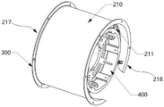
图1为本发明提供一种流体离心贯流作用结构体实施例一的结构示意图;1 is a schematic structural diagram of Embodiment 1 of a fluid centrifugal through-flow structure provided by the present invention;
图2为本发明提供一种流体离心贯流作用结构体实施例二的结构示意图;2 is a schematic structural diagram of Embodiment 2 of a fluid centrifugal through-flow structure body provided by the present invention;
图3为本发明提供一种驱动支承结构设为与导流条悬置端嵌入固定装置结构的导流结构体示意图;3 is a schematic diagram of a flow guide structure provided by the present invention with a drive support structure set as a structure of embedding a fixing device with the suspension end of the guide bar;
图4为本发明提供一种流体离心贯流作用装置实施例一的结构示意图;4 is a schematic structural diagram of Embodiment 1 of a fluid centrifugal through-flow device provided by the present invention;
图5为导流结构体中组合式导流条采用榫合连接的结构示意图;FIG. 5 is a schematic structural diagram of a combined flow guide strip in a flow guide structure using tenon joint connection;
图6为导流结构体中组合式导流条采用插片连接的结构示意图;FIG. 6 is a schematic structural diagram of the combined guide bar in the guide structure body using inserts to connect;
图7为导流结构体中组合式导流条采用连接片连接的结构示意图;FIG. 7 is a schematic structural diagram of a combined guide strip connected by a connecting piece in a guide structure;
图8为导流条一体成型围构直筒结构实施例一的结构示意图;8 is a schematic structural diagram of Embodiment 1 of the straight-tube structure of the integrally formed surrounding structure of the guide strip;
图9为导流条一体成型围构直筒结构实施例二的结构示意图;9 is a schematic structural diagram of Embodiment 2 of the straight-tube structure of the integrally formed surrounding structure of the guide strip;
图10为导流面呈曲面的导流条件示意图;Fig. 10 is a schematic diagram of the diversion conditions when the diversion surface is a curved surface;
图11为导流面呈平面的导流条件示意图;Fig. 11 is a schematic diagram of the diversion condition with the diversion surface being a plane;
图12为导流面呈折面的导流条件示意图;Fig. 12 is a schematic diagram of the diversion conditions when the diversion surface is a folded surface;
图13为导流条的导流面流体流出端取变向导流结构的实施例一的示意图;13 is a schematic diagram of the first embodiment of the flow guide structure in which the flow outflow end of the guide surface of the guide bar is changed to a guide structure;
图14为导流条的导流面流体流出端取变向导流结构的实施例二的示意图;14 is a schematic diagram of the second embodiment of the flow guide structure in which the flow outflow end of the guide surface of the guide strip is changed to a guide structure;
图15为导流面呈不等分流道的导流条结构示意图;15 is a schematic diagram of the structure of the guide strip with the guide surface being unequally divided flow channels;
图16为导流面呈等分流道的导流条结构示意图;16 is a schematic diagram of the structure of the guide strip with the guide surface in the form of an equally divided flow channel;
图17为设有嵌入装置槽的导流条的结构示意图;FIG. 17 is a schematic structural diagram of a guide bar provided with an embedded device slot;
图18为导流面左旋设置的导流条的结构示意图;FIG. 18 is a schematic structural diagram of a guide strip with a left-handed setting on the guide surface;
图19为导流面右旋设置的导流条的结构示意图;Figure 19 is a schematic structural diagram of a guide strip with a clockwise arrangement on the guide surface;
图20为一种导流体流出侧悬置端设开放结构的导流结构体的结构示意图;20 is a schematic structural diagram of a flow guide structure with an open structure at the suspension end on the outflow side of the guide body;
图21为一种导流体流出侧悬置端呈封闭结构的导流结构体的结构示意图;FIG. 21 is a schematic structural diagram of a flow-guiding structure body with a suspension end on the outflow side of the guide-fluid having a closed structure;
图22为封闭结构外延的导流结构体的结构示意图;22 is a schematic structural diagram of a closed-structure epitaxial flow-guiding structure;
图23为一种驱动支承结构兼封闭流出侧悬置端的导流机构体的结构示意图;Figure 23 is a schematic structural diagram of a flow guiding mechanism body that drives the supporting structure and closes the outflow side suspension end;
图24为一种导流体流出侧悬置端增设导流内筒的流体离心贯流作用结构体的结构示意图;24 is a schematic structural diagram of a fluid centrifugal through-flow structure body with an additional flow-guiding inner cylinder at the suspension end of the flow-guiding fluid outflow side;
图25为一种流体离心贯流作用装置实施例二的结构示意图;25 is a schematic structural diagram of Embodiment 2 of a fluid centrifugal through-flow device;
图26为一种流体离心贯流作用装置实施例三的结构示意图。FIG. 26 is a schematic structural diagram of Embodiment 3 of a fluid centrifugal through-flow device.
附图标记:Reference number:
100离心叶轮 210导流结构体 211导流条100
212导流面 213流道 214嵌入装置槽212
215环状结构体 216外套筒 217流体入口215
218流体出口 221榫凸 222榫槽218
223插槽 224插片 225连接槽223
226连接片 230导流内筒 300流体入口结构226 connecting
400驱动支承结构 500驱动源400
具体实施方式Detailed ways
为使本发明实施例的目的、技术方案和优点更加清楚,下面将结合本发明实施例中的附图,对本发明实施例中的技术方案进行清楚、完整地描述,显然,所描述的实施例是本发明一部分实施例,而不是全部的实施例。基于本发明中的实施例,本领域普通技术人员在没有作出创造性劳动前提下所获得的所有其他实施例,都属于本发明保护的范围。In order to make the purposes, technical solutions and advantages of the embodiments of the present invention clearer, the technical solutions in the embodiments of the present invention will be clearly and completely described below with reference to the accompanying drawings in the embodiments of the present invention. Obviously, the described embodiments These are some embodiments of the present invention, but not all embodiments. Based on the embodiments of the present invention, all other embodiments obtained by those of ordinary skill in the art without creative efforts shall fall within the protection scope of the present invention.
术语解释:本发明中将“流体以离心方式进入,以轴流方式输出”的方式定义为“离心贯流”。 Explanation of terms : In the present invention, the way in which "fluid enters in a centrifugal way and outputs in an axial flow way" is defined as "centrifugal flow".
本发明提供一种流体离心贯流作用结构体,如图1或图2所示,流体离心贯流作用结构体包括:导流结构体210,流体入口结构300和驱动支承结构400;导流结构体210取为由若干导流条211围构成的直筒结构;流体入口结构300取为适配离心叶轮流体输入的结构设于直筒结构的流体入端,构成流体离心贯流作用结构体的流体入口;直筒结构的流体出端构成流体离心贯流作用结构体的流体出口;导流条211内侧悬置端围构空间构成离心叶轮的装置空间;所述驱动支承结构400设置在所述导流条211内侧的悬置端上并位于装置离心叶轮的空间之后。The present invention provides a fluid centrifugal cross-flow structure. As shown in FIG. 1 or FIG. 2, the fluid centrifugal cross-flow structure includes: a
需要说明的是,流体入口结构300与导流结构体210可以根据不同的制造工艺选择一体成型或者连接组合而成。It should be noted that, the
进一步地,为了适配离心叶轮流体输入的结构,所述流体入口的内侧口径不大于离心叶轮流体入口的口径,内侧口径为对向向离心叶轮的输送风的入口。如图1所示,所述流体入口300的结构为漏斗型结构。Further, in order to adapt to the structure of the centrifugal impeller fluid input, the inner diameter of the fluid inlet is not larger than the diameter of the centrifugal impeller fluid inlet, and the inner diameter is the inlet of the conveying air opposite to the centrifugal impeller. As shown in FIG. 1 , the structure of the
进一步地,如图1所示,在所述导流条的流体出端之后还设有流量负压扩增结构体。流量负压扩增结构体为包括有出端内流体通道和出端外流体输入通道的壳体;出端外流体输入通道的出口与出端内流体通道相通。需要说明的是,出端流量负压扩增结构体应用于流体作用装置时,出端内流体通道为流体作用装置的流体导流通道;当流体作用装置的内部流动流体在出端内流体通道高速流动时,流体会在出端外流体输入通道的入口处产生相对于出端外流体输入通道入口的负压,在负压作用下,外流体从出端外流体通道的入口流入至出端内流体通道内参与内流体的流动,从而实现扩流。此外,出端流量负压扩增结构体与流体作用装置的导流体可以是一体成型结构或者为组合式结构。Further, as shown in FIG. 1 , a flow negative pressure amplification structure is further provided behind the fluid outlet end of the guide strip. The flow negative pressure amplification structure is a shell including a fluid channel in the outlet end and a fluid input channel outside the outlet end; the outlet of the fluid input channel outside the outlet end communicates with the fluid channel in the outlet end. It should be noted that when the negative pressure amplification structure at the outlet end is applied to the fluid action device, the fluid channel in the outlet end is the fluid guide channel of the fluid action device; When flowing at high speed, the fluid will generate a negative pressure at the inlet of the outer fluid input channel at the outlet end relative to the inlet of the outer fluid input channel at the outlet end. Under the action of the negative pressure, the outer fluid flows from the inlet of the outer fluid channel at the outlet end to the outlet end. Participate in the flow of the inner fluid in the inner fluid channel, thereby realizing flow expansion. In addition, the outlet flow negative pressure amplification structure and the conducting body of the fluid action device may be an integrally formed structure or a combined structure.
本发明提供的流体离心贯流作用结构体工作原理为离心叶轮受安装在驱动支承结构400的驱动源驱动旋转,将自流体入口输入的流体通过离心叶轮作用使之横向流向导流结构体的导流面,再经导流结构体的导流面导流,使流体流转向向直筒结构的出口流出。The working principle of the fluid centrifugal cross-flow structure provided by the present invention is that the centrifugal impeller is driven to rotate by the driving source installed on the driving
进一步地,所述驱动支承结构设为与导流条悬置端嵌入固定装置结构,导流条悬置端设有针对驱动支承结构的嵌入装置槽;或者设为与导流条悬置端一体结构的固定结构;还或是设为于导流条悬置端设置一体化用于驱动支承结构插入套合装置的环状体,驱动支承结构取为独立结构,以插入套合和获得紧固件紧固的固定装置。Further, the driving support structure is configured to be embedded in a fixing device structure with the suspension end of the guide bar, and the suspension end of the guide bar is provided with an embedding device slot for the driving support structure; or is set to be integrated with the suspension end of the guide bar. The fixing structure of the structure; it is also possible to set an annular body integrated at the suspension end of the guide bar for driving the support structure to be inserted into the sleeve device, and the drive support structure is taken as an independent structure to insert the sleeve and obtain the fastening. Fastening fixtures.
具体实施时,如图3所示,驱动支承结构400设为与导流条211悬置端嵌入固定装置结构,导流条211悬置端设有针对驱动支承结构的嵌入装置槽214;In specific implementation, as shown in FIG. 3 , the driving
可选地,驱动支承结构400设为与导流条211悬置端一体结构的固定结构;还或是,驱动支承结构400设为于导流条悬置端设置一体化用于驱动支承结构插入套合装置的环状体,驱动支承结构400取为独立结构,以插入套合和获得紧固件紧固的固定装置。Optionally, the driving
进一步地,所述驱动支承结构设置在所述导流条内侧的悬置端上的安装固定件上,所述安装固定件与所述导流条内侧的悬置端为一体成型或者连接组合而成。Further, the driving support structure is arranged on the mounting fixture on the suspension end on the inner side of the guide bar, and the mounting fixture is integrally formed or connected and combined with the suspension end on the inner side of the guide bar. to make.
需要说明的是,本发明提供的驱动支承结构与导流条悬置端的安装模式实施例仅是为了说明驱动支承结构可设置于导流条悬置端,凡是为了实现驱动支承结构与导流条悬置端的安装的其它结构也均属于本发明保护的范围。It should be noted that the embodiment of the installation mode of the drive support structure and the suspension end of the guide bar provided by the present invention is only to illustrate that the drive support structure can be arranged at the suspension end of the guide bar. Other structures for the installation of the suspension end also belong to the protection scope of the present invention.
进一步地,所述驱动支承结构400设为装置驱动马达的机座。具体实施时,如图1和图2所示,驱动支承结构400设为装置驱动马达的机座,用于安装内置驱动源。Further, the driving
进一步地,所述驱动支承结构400设为支承传动轴的轴承座。具体实施时,如图4所示,驱动支承结构400设为支承传动轴的轴承座,可在驱动支承结构400设置传动轴用于连接外置驱动源。Further, the
需要说明的是,驱动支承结构除了用作驱动马达的机座和支承传动轴的轴承座,凡是为了支承驱动源所作的结构改进也均属于本发明保护的范围。It should be noted that the drive support structure is not only used as the base of the drive motor and the bearing seat for supporting the transmission shaft, all structural improvements made to support the drive source also belong to the scope of protection of the present invention.
进一步地,若干所述导流条211通过榫合连接结构、插片连接结构或连接片连接结构组合构成直筒结构。Further, a plurality of the guide strips 211 are combined to form a straight cylinder structure through a tenon joint connection structure, a plug connection structure or a connection piece connection structure.
具体实施时,如图5所示,组合式导流条211可以通过榫合结构连接。相邻的导流条211可以在连接部位设置相吻合的榫凸221和榫槽222。During specific implementation, as shown in FIG. 5 , the combined guide strips 211 may be connected by a tenon structure. The adjacent guide strips 211 may be provided with matching
具体实施时,如图6所示,组合式导流条211可以通过插片连接。相邻的导流条211可以在首端或尾端设置相吻合的插槽223和插片224,也可以在首尾两端或者还包括中间位置均设置相吻合的插槽223和插片224。During specific implementation, as shown in FIG. 6 , the combined guide strips 211 may be connected through inserts. The adjacent guide strips 211 may be provided with matching
具体实施时,如图7所示,组合式导流条211可以通过连接片连接。相邻导流条211可以在首端或尾端设置相吻合的连接槽225和连接片226,也可以在首尾两端均设置相吻合的连接槽225和连接片226。During specific implementation, as shown in FIG. 7 , the combined guide bars 211 may be connected by connecting pieces. The adjacent guide strips 211 may be provided with
需要说明的是,所述组合式导流条的榫合、插片、连接片实施例组合结构形式仅仅是举例,凡能够实现相邻导流条的相互位置、方向定位,或者还包括相互连接固定,使若干导流条能够形成一个环状结构体的任何组合方式均可利用。It should be noted that the combined structure of the tenon joint, insert piece, and connecting piece of the combined guide strip is only an example, and the mutual position and direction positioning of the adjacent guide strips can be realized, or the mutual connection is also included. Fixed, any combination that enables several guide strips to form an annular structure can be used.
进一步地,流体离心贯流作用结构体还包括外套筒216,所述导流结构体210设置于外套筒216内。Further, the fluid centrifugal through-flow structure body further includes an
进一步地,所述外套筒长度大于内置的导流条长度。Further, the length of the outer sleeve is greater than the length of the built-in guide strip.
具体实施时,如图5-7所示,将导流结构体210设置成由若干独立结构组合而成的环状结构体215,再与外套筒216嵌套形成流体的组合式离心贯流筒体,支持改善导流结构体的制成工艺,提高加工效率。In specific implementation, as shown in FIGS. 5-7 , the
进一步地,若干所述导流条一体成型围构直筒结构。具体实施时,如图8和图9所示,导流结构体210为具有导流功能的一体成型结构,内表面分布有若干导流条211。Further, a plurality of the guide strips are integrally formed to enclose a straight cylindrical structure. During specific implementation, as shown in FIGS. 8 and 9 , the
进一步地,如图8所示,根据具体的使用场景,导流条211可以右旋分布于导流结构体210内表面。Further, as shown in FIG. 8 , according to specific usage scenarios, the guide strips 211 may be clockwise distributed on the inner surface of the
可选地,如图9所示,导流条211还可以左旋分布于导流结构体210内表面。Optionally, as shown in FIG. 9 , the guide strips 211 may also be left-handedly distributed on the inner surface of the
进一步地,所述导流条的导流面呈曲面结构、平面结构、折面结构中的一种或一种以上的组合面结构。Further, the guide surface of the guide bar is one or more of a combined surface structure selected from a curved surface structure, a planar structure, and a folded surface structure.
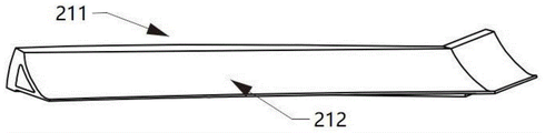
具体实施时,如图10-14所示,导流条211的导流面212可以为曲面、平面或者折面的结构。具体根据使用场景,导流条211的导流面212还可以是曲面、平面、折面三者中部分或全部组合结构。During specific implementation, as shown in FIGS. 10-14 , the
进一步地,所述导流条的导流面的流体流出端设置为变向导流结构。Further, the fluid outflow end of the guide surface of the guide bar is configured as a variable guide structure.
进一步地,所述变向导流结构将所述导流面分为前导流面与后导流面;所述后导流面的导流流体流动方向与所述导流结构体的轴线方向平行。Further, the diversion guide structure divides the guide surface into a front guide surface and a rear guide surface; the flow direction of the guide fluid on the rear guide surface is parallel to the axial direction of the guide structure. .
进一步地,所述变向导流结构将所述导流面分为前导流面与后导流面;所述后导流面的导流流体流动方向与前导流面导流流体流动方向形成反向夹角。Further, the changing diversion structure divides the diversion surface into a front diversion surface and a rear diversion surface; the flow direction of diversion fluid on the rear diversion surface and the flow direction of diversion fluid on the front diversion surface are formed. Reverse angle.
具体实施时,将导流条的导流面设置成变向导流结构和选择采用变向导流结构,可以获得流体离心贯流作用装置流体输出端的设定流向的流场,支持离心贯流作用装置流体输出端的后续流体应用流场需要,平行情况的无预旋流场;夹角情况的反向预旋流场是其典型实施例。In specific implementation, the guide surface of the guide bar is set to a variable guide structure and the variable guide structure is selected to obtain the flow field of the set flow direction of the fluid output end of the fluid centrifugal through-flow action device, which supports the centrifugal through-flow action device. The subsequent fluid application flow field at the fluid output end requires no pre-swirl flow field in the parallel case; reverse pre-swirl flow field in the included angle case is a typical example thereof.
如图13和图14所示,导流条211本身的导流面212流体流出端可以取变向导流结构,导流面212的流体输出端方向可以与导流结构体210的轴线方向平行或者形成与导流条211的导流面212的反向夹角,以实现导流条211针对流体导向方向的改变。As shown in FIG. 13 and FIG. 14 , the fluid outflow end of the guiding
进一步地,在所述导流条的导流面一侧设有凸出于导流面的至少一条分流条,所述分流条将所述导流面分割成可实施流量重新分配的不同流道。Further, at least one diversion strip protruding from the diversion surface is provided on one side of the diversion surface of the diversion strip, and the diversion strip divides the diversion surface into different flow channels that can implement flow redistribution. .
具体实施时,将导流条的导流面设置成由凸起结构分割成的多个流道的导流面由各流道对经离心叶轮作用送出的径向运动流体在分流过程中实施流量分配,可以获得流体离心贯流作用装置流体输出端的设定流量的流场,支持流体离心贯流作用装置流体输出端的后续流体应用流场需要,以最终实现经导流条的全导流面的导流流体在导流条的流体出端沿导流结构体径向方向的由流道宽窄决定的量的分布,由此使得流体离心贯流作用装置的流体出端流场分布成为可根据使用对象或具体使用场景需要实施人为设置的预设性流场。In specific implementation, the guide surface of the guide bar is set as the guide surface of a plurality of flow channels divided by the convex structure, and the flow of the radial moving fluid sent out by the centrifugal impeller is implemented by each flow channel during the flow splitting process. Distribution, the flow field of the set flow rate at the fluid output end of the fluid centrifugal through-flow action device can be obtained, and the subsequent fluid application flow field needs of the fluid output end of the fluid centrifugal through-flow action device can be obtained, so as to finally realize the full diversion surface of the flow guide bar. The distribution of the diversion fluid at the fluid outlet end of the diversion bar along the radial direction of the diversion structure body is determined by the width of the flow channel, so that the flow field distribution of the fluid outlet end of the fluid centrifugal cross-flow device can be used according to the use. Objects or specific usage scenarios need to implement artificially set preset flow fields.
具体实施时,如图15所示,导流条211的导流面212可以由若干不等分的流道213构成,也可以如图16所示,导流条211的导流面212由若干等分的流道213构成。In specific implementation, as shown in FIG. 15 , the
进一步地,如图17所示,导流条211悬置端还可以预设嵌入装置槽214,嵌入装置槽214可以用于后续驱动源内置机座的安装。所述导流条211悬置端即导流条211与离心叶轮相对最接近的一侧,因它没有依附,而与悬置端相对的导流条211的另一侧与筒体相结合;因与悬置端相对的导流条211的另一侧依附于筒体内表面,所以导流条211的另一侧不存在悬置关系。Further, as shown in FIG. 17 , the suspension end of the
进一步地,如图17和图18所示,导流条211可以为实心结构或者空心结构。Further, as shown in FIG. 17 and FIG. 18 , the
进一步地,如图18和图19所示,根据具体的使用场景,导流条211本身的导流面212也可以设置右旋、左旋的方式。图18和图19的旋转的角度在此不做具体限定。Further, as shown in FIG. 18 and FIG. 19 , according to specific usage scenarios, the
进一步地,将导流条211的位于相对于离心叶轮之后的导流面以渐变方式设置成扩展面结构,可以实现流体离心贯流作用装置流体输出端的流场面积的改变。Further, the guide surface of the
需要说明的是,上述术语“导流条”只是为了描述实施例使用,并非限定一定是“条”状,“导流条”可以是片状结构,条状结构,或者是其它立体结构,均落入本发明的保护范围内。It should be noted that the above term "guiding strip" is only used to describe the embodiment, and is not limited to be in the shape of a "strip". fall within the protection scope of the present invention.
为了使导流结构体的流体输出方式能够适用不同场景需求,及丰富导流结构体的结构。本发明还对导流结构体的流体输出端结构进行改进。针对导流结构体位于离心叶轮后部的流体输出端悬置端,用环带结构体对其实施封闭,可对导流结构体流出流体的流场实现约束。In order to make the fluid output mode of the diversion structure suitable for different scene requirements, and to enrich the structure of the diversion structure. The present invention also improves the structure of the fluid output end of the flow guiding structure. For the suspension end of the fluid output end of the flow guide structure located at the rear of the centrifugal impeller, the annular belt structure is used to seal it, which can constrain the flow field of the fluid flowing out of the flow guide structure.
图20为一种导流体流出侧悬置端设开放结构的导流结构体,该导流结构体为基础型导流结构体。Fig. 20 shows a flow guide structure with an open structure at the suspension end on the outflow side of the guide body, and the flow guide structure is a basic flow guide structure.
图21为一种导流体流出侧悬置端呈封闭结构的导流结构体,该封闭结构有由驱动支承结构400边缘结构延伸形成,该导流结构体210能够对输出流体起到束流作用。Fig. 21 shows a flow-guiding structure with the suspension end on the outflow side of the guiding fluid in a closed structure. The closed structure is formed by extending the edge structure of the driving
进一步地,如图22所示,驱动支承结构400还可延长至筒体外。Further, as shown in FIG. 22 , the driving
进一步地,图23为一种驱动源装置座兼封闭流出侧悬置端的导流机构体,该封闭结构由驱动源装置座的侧面结构构成,该导流结构体同样能够对输出流体起到束流作用。Further, FIG. 23 is a guide mechanism body of a drive source device seat and a closed outflow side suspension end, the closed structure is formed by the side structure of the drive source device seat, and the guide structure body can also play a beam on the output fluid. flow effect.
进一步地,图24为一种导流体211流出侧悬置端增设导流内筒230的导流结构体210。Further, FIG. 24 is a
本发明提供的流体离心贯流作用结构体可以应用于透平式流体作用装置中,从而创造出一种全新模式的透平式流体作用装置,即一种透平式流体离心贯流作用装置,它能有效解决现有离心透平式流体作用装置无法有效改变流体流向与使流体进出离心透平式流体作用装置的方向共轴同向的统一性问题,并且与现有离心透平式流体作用装置比较,显著地缩短流体输送方向变向所经历的路径长度,减少流体流向变化过程中流体的压力损失,可显著提高透平式流体作用装置的工作效率。如图25或图26所示,一种流体离心贯流作用装置包括离心叶轮100和离心贯流导流筒体;其中,所述离心贯流导流筒体内表面设有导流结构体210,所述离心叶轮100部署于所述导流结构体210内部空间内。The fluid centrifugal cross-flow action structure provided by the present invention can be applied to a turbine-type fluid action device, thereby creating a new model of the turbine-type fluid action device, that is, a turbine-type fluid centrifugal cross-flow action device, It can effectively solve the problem that the existing centrifugal turbine type fluid action device cannot effectively change the fluid flow direction and the direction of the fluid entering and exiting the centrifugal turbine type fluid action device is coaxial and coaxial, and the existing centrifugal turbine type fluid action device. Compared with the device, the path length of the fluid conveying direction change can be significantly shortened, the pressure loss of the fluid in the process of changing the fluid flow direction can be reduced, and the working efficiency of the turbine-type fluid action device can be significantly improved. As shown in FIG. 25 or FIG. 26 , a fluid centrifugal through-flow action device includes a
具体实施时,所述导流结构体210可以由若干沿轴线方向延伸的导流条211组成,也可以是具有导流功能的一体成型结构。During specific implementation, the
具体实施时,离心贯流导流筒体可以是由所述导流结构体210整体的外表面组合而成,也可以是独立外套筒结构。该独立外套筒结构可以由刚性材料、柔性材料结构或者带状材料缠绕制备和高分子材料制备而成。In specific implementation, the centrifugal cross-flow guide cylinder may be formed by combining the entire outer surfaces of the
进一步地,如图25所示,流体入口结构300取为斗体结构,斗体的流体出口与离心叶轮的流体入口适配。Further, as shown in FIG. 25 , the
可选地,如图26所示,流体入口结构300设为与直筒结构的流体入端的组合固装结构。Optionally, as shown in FIG. 26 , the
需要说明的是,流体入口结构300除了取斗体结构、与直筒结构的流体入端的一体化结构、与直筒结构的流体入端的组合固装结构外,凡是为了在导流结构体210上设置的流体入口的结构也均属于本发明的保护范围。It should be noted that, in addition to the bucket body structure, the integrated structure with the fluid inlet end of the straight-tube structure, and the combined fixed structure with the fluid inlet end of the straight-tube structure, the
本发明提供的流体离心贯流作用装置的作用原理为:离心叶轮100受驱动源驱动旋转,使得流体从离心贯流导流筒体的进口(或称入口)输入;流体受离心叶轮100作用,使得流体以垂直离心贯流筒体轴线的方向到达导流结构体210的导流面212;在导流结构体210的导流面212设定的结构导流作用下,将使流体流向从垂直于离心贯流导流筒体200轴线方向变成绕离心贯流导流筒体轴线流动或平行离心贯流导流筒体轴线流动,从而获得一种流体离心贯流作用方式。The working principle of the fluid centrifugal through-flow action device provided by the present invention is as follows: the
该流体离心贯流作用装置利用离心叶轮和离心贯流导流筒体的协同结合,可以达到流体以离心方式进入,以轴流方式输出,使得轴流流体作用装置与离心流体作用装置各自优点更优化地结合。该离心贯流作用装置,不仅实现了在流体通路中串装使用,利于流体通路的简化与优化设计,还能够提高流体驱动的工作效率,且可以显著将流体作用装置的体积缩小。The fluid centrifugal flow action device utilizes the synergistic combination of the centrifugal impeller and the centrifugal flow guide cylinder, so that the fluid can enter in a centrifugal way and output in an axial flow way, so that the respective advantages of the axial flow fluid action device and the centrifugal fluid action device are better. Optimally combined. The centrifugal through-flow action device can not only be used in series in the fluid passage, which is beneficial to the simplification and optimal design of the fluid passage, but also can improve the working efficiency of the fluid drive, and can significantly reduce the volume of the fluid action device.
在本发明的描述中,需要说明的是,术语“中心”、“纵向”、“横向”、“上”、“下”、“前”、“后”、“左”、“右”、“竖直”、“水平”、“顶”、“底”、“内”、“外”等指示的方位或位置关系为基于附图所示的方位或位置关系,仅是为了便于描述本发明和简化描述,而不是指示或暗示所指的装置或元件必须具有特定的方位、以特定的方位构造和操作,因此不能理解为对本发明的限制。此外,术语“第一”、“第二”仅用于描述目的,而不能理解为指示或暗示相对重要性。In the description of the present invention, it should be noted that the terms "center", "portrait", "horizontal", "top", "bottom", "front", "rear", "left", "right", " The orientation or positional relationship indicated by vertical, horizontal, top, bottom, inner, outer, etc. is based on the orientation or positional relationship shown in the drawings, and is only for the convenience of describing the present invention and The description is simplified rather than indicating or implying that the device or element referred to must have a particular orientation, be constructed and operate in a particular orientation, and therefore should not be construed as limiting the invention. Furthermore, the terms "first" and "second" are used for descriptive purposes only and should not be construed to indicate or imply relative importance.
最后应说明的是:以上各实施例仅用以说明本发明的技术方案,而非对其限制;尽管参照前述各实施例对本发明进行了详细的说明,本领域的普通技术人员应当理解:其依然可以对前述各实施例所记载的技术方案进行修改,或者对其中部分或者全部技术特征进行等同替换;而这些修改或者替换,并不使相应技术方案的本质脱离本发明各实施例技术方案的范围。Finally, it should be noted that the above embodiments are only used to illustrate the technical solutions of the present invention, but not to limit them; although the present invention has been described in detail with reference to the foregoing embodiments, those of ordinary skill in the art should understand that: The technical solutions described in the foregoing embodiments can still be modified, or some or all of the technical features thereof can be equivalently replaced; and these modifications or replacements do not make the essence of the corresponding technical solutions deviate from the technical solutions of the embodiments of the present invention. scope.
Claims (16)
Applications Claiming Priority (2)
| Application Number | Priority Date | Filing Date | Title |
|---|---|---|---|
| CN2018114480750 | 2018-11-29 | ||
| CN201811448075 | 2018-11-29 |
Publications (2)
| Publication Number | Publication Date |
|---|---|
| CN111237217A CN111237217A (en) | 2020-06-05 |
| CN111237217B true CN111237217B (en) | 2022-08-30 |
Family
ID=70852652
Family Applications (13)
| Application Number | Title | Priority Date | Filing Date |
|---|---|---|---|
| CN201922106598.3U Expired - Fee Related CN211370785U (en) | 2018-11-29 | 2019-11-29 | A centrifugal tubular propulsion device for diving |
| CN201922108275.8U Expired - Fee Related CN211901014U (en) | 2018-11-29 | 2019-11-29 | Centrifugal through-flow water navigation body propulsion device and application equipment |
| CN201911205910.2A Pending CN111237214A (en) | 2018-11-29 | 2019-11-29 | A centrifugal cross-flow air body traction device and its application |
| CN201911205948.XA Pending CN111237216A (en) | 2018-11-29 | 2019-11-29 | Centrifugal through-flow water navigation body propulsion device and application |
| CN201922107462.4U Expired - Fee Related CN211874763U (en) | 2018-11-29 | 2019-11-29 | A radial out-shaft fluid counter-rotation action device and fan |
| CN201922106595.XU Expired - Fee Related CN211901013U (en) | 2018-11-29 | 2019-11-29 | Fluid centrifugal through-flow device with external driving source and fan |
| CN201922108723.4U Active CN211370786U (en) | 2018-11-29 | 2019-11-29 | A flow-amplifying fluid centrifugal through-flow device |
| CN201922108714.5U Expired - Fee Related CN211874765U (en) | 2018-11-29 | 2019-11-29 | A centrifugal cross-flow high-speed water and mist spray device |
| CN201911203654.3A Pending CN111237212A (en) | 2018-11-29 | 2019-11-29 | Fluid centrifugal cross-flow action device without driving source and fan |
| CN201911203657.7A Pending CN111237213A (en) | 2018-11-29 | 2019-11-29 | A fluid centrifugal through-flow device with an external drive source and a fan |
| CN201911207678.6A Active CN111237217B (en) | 2018-11-29 | 2019-11-29 | Fluid centrifugal through-flow action structure |
| CN201911205943.7A Pending CN111237215A (en) | 2018-11-29 | 2019-11-29 | Large-flow high-full-pressure reloading centrifugal cross-flow fan |
| CN201922108297.4U Expired - Fee Related CN211874764U (en) | 2018-11-29 | 2019-11-29 | A large flow and high full pressure reloaded centrifugal cross-flow fan |
Family Applications Before (10)
| Application Number | Title | Priority Date | Filing Date |
|---|---|---|---|
| CN201922106598.3U Expired - Fee Related CN211370785U (en) | 2018-11-29 | 2019-11-29 | A centrifugal tubular propulsion device for diving |
| CN201922108275.8U Expired - Fee Related CN211901014U (en) | 2018-11-29 | 2019-11-29 | Centrifugal through-flow water navigation body propulsion device and application equipment |
| CN201911205910.2A Pending CN111237214A (en) | 2018-11-29 | 2019-11-29 | A centrifugal cross-flow air body traction device and its application |
| CN201911205948.XA Pending CN111237216A (en) | 2018-11-29 | 2019-11-29 | Centrifugal through-flow water navigation body propulsion device and application |
| CN201922107462.4U Expired - Fee Related CN211874763U (en) | 2018-11-29 | 2019-11-29 | A radial out-shaft fluid counter-rotation action device and fan |
| CN201922106595.XU Expired - Fee Related CN211901013U (en) | 2018-11-29 | 2019-11-29 | Fluid centrifugal through-flow device with external driving source and fan |
| CN201922108723.4U Active CN211370786U (en) | 2018-11-29 | 2019-11-29 | A flow-amplifying fluid centrifugal through-flow device |
| CN201922108714.5U Expired - Fee Related CN211874765U (en) | 2018-11-29 | 2019-11-29 | A centrifugal cross-flow high-speed water and mist spray device |
| CN201911203654.3A Pending CN111237212A (en) | 2018-11-29 | 2019-11-29 | Fluid centrifugal cross-flow action device without driving source and fan |
| CN201911203657.7A Pending CN111237213A (en) | 2018-11-29 | 2019-11-29 | A fluid centrifugal through-flow device with an external drive source and a fan |
Family Applications After (2)
| Application Number | Title | Priority Date | Filing Date |
|---|---|---|---|
| CN201911205943.7A Pending CN111237215A (en) | 2018-11-29 | 2019-11-29 | Large-flow high-full-pressure reloading centrifugal cross-flow fan |
| CN201922108297.4U Expired - Fee Related CN211874764U (en) | 2018-11-29 | 2019-11-29 | A large flow and high full pressure reloaded centrifugal cross-flow fan |
Country Status (2)
| Country | Link |
|---|---|
| CN (13) | CN211370785U (en) |
| WO (1) | WO2020108655A1 (en) |
Families Citing this family (3)
| Publication number | Priority date | Publication date | Assignee | Title |
|---|---|---|---|---|
| CN211370785U (en) * | 2018-11-29 | 2020-08-28 | 曾固 | A centrifugal tubular propulsion device for diving |
| CN114183386B (en) * | 2021-09-27 | 2025-03-04 | 深圳市几素科技有限公司 | Pressurized mixed flow generator and portable bladeless fan equipped with the same |
| CN113884267B (en) * | 2021-12-07 | 2022-02-25 | 中国空气动力研究与发展中心超高速空气动力研究所 | Transient jet flow test device for pulse wind tunnel |
Citations (10)
| Publication number | Priority date | Publication date | Assignee | Title |
|---|---|---|---|---|
| CN200968294Y (en) * | 2006-10-20 | 2007-10-31 | 陈耀乾 | Linear centrifugal fan structure |
| CN102162470A (en) * | 2011-03-02 | 2011-08-24 | 杭州日通风机有限公司 | Pipeline-type axial flow centrifugal fan and eccentric flow guiding method |
| CN202900707U (en) * | 2012-10-29 | 2013-04-24 | 江苏兆胜空调有限公司 | Air supply device of mixed flow blower |
| CN104564742A (en) * | 2014-12-30 | 2015-04-29 | 上虞市鹏翔暖通设备有限公司 | Centrifugal type axial flow fan |
| CN104948502A (en) * | 2014-03-26 | 2015-09-30 | 陈玉沛 | Flow guides for centrifugal impellers |
| CN105370600A (en) * | 2015-12-18 | 2016-03-02 | 中车大连机车研究所有限公司 | Centrifugal axial flow traction ventilator for electric locomotive |
| CN106321525A (en) * | 2016-11-15 | 2017-01-11 | 美的集团股份有限公司 | Base and bladeless fan |
| CN106593949A (en) * | 2016-09-12 | 2017-04-26 | 东莞市卓奇电子科技有限公司 | Split impeller |
| CN207049046U (en) * | 2017-08-11 | 2018-02-27 | 郑州新光矿山机械制造有限公司 | Diagonal flow type water conservancy diversion axial flow blower |
| CN208153351U (en) * | 2018-04-16 | 2018-11-27 | 威海克莱特菲尔风机股份有限公司 | Centrifugal axial flow-type marine fan |
Family Cites Families (23)
| Publication number | Priority date | Publication date | Assignee | Title |
|---|---|---|---|---|
| DE3568614D1 (en) * | 1985-09-05 | 1989-04-13 | Howden James & Co Ltd | Centrifugal fans and blowers |
| GB2244098A (en) * | 1990-05-17 | 1991-11-20 | Secr Defence | Variable configuration gas turbine engine |
| CN2332834Y (en) * | 1997-11-17 | 1999-08-11 | 卞锡培 | Multi-kinds wheel dragging cyclone fan |
| US6589013B2 (en) * | 2001-02-23 | 2003-07-08 | Macro-Micro Devices, Inc. | Fluid flow controller |
| CA2429204A1 (en) * | 2003-05-16 | 2004-11-16 | Mikulas Pohanka | Propulsion system of a ship, by ejection of water with a pump |
| TWM266364U (en) * | 2004-09-06 | 2005-06-01 | Shiou-Ying Chen | Improved structure of blower |
| CN201003499Y (en) * | 2006-07-24 | 2008-01-09 | 黄贞秋 | Water turbine axial flow fan for gas water heater |
| FR2908482B1 (en) * | 2006-11-13 | 2010-04-02 | Airfan | REGULATED DELIVERY APPARATUS FOR A GAS, PARTICULARLY RESPIRATORY ASSISTANCE APPARATUS |
| US8205454B2 (en) * | 2007-02-06 | 2012-06-26 | United Technologies Corporation | Convergent divergent nozzle with edge cooled divergent seals |
| CN201173198Y (en) * | 2008-03-31 | 2008-12-31 | 黄宇涛 | Electric energy-free water-driven blower fan |
| CN201176967Y (en) * | 2008-04-14 | 2009-01-07 | 魏高翔 | Centrifugal blower fan flow guiding structure capable of producing uniform speed airflow of same direction |
| CN201288679Y (en) * | 2008-11-10 | 2009-08-12 | 北京得能创新科技有限公司 | Dual driving apparatus for steam turbine and electric motor |
| CN202673724U (en) * | 2012-08-10 | 2013-01-16 | 青岛艾特尔机械电子科技有限公司 | Mixed flow fan |
| CN203257699U (en) * | 2013-02-22 | 2013-10-30 | 吴钰 | Double-duct draught fan |
| CN103225625A (en) * | 2013-03-28 | 2013-07-31 | 无锡小天鹅股份有限公司 | Centrifugal fan and clothes dryer with same |
| CN103486058B (en) * | 2013-08-19 | 2016-02-03 | 平安电气股份有限公司 | Motor side external formula one drag two counter-rotating axial fan |
| US9656755B2 (en) * | 2013-12-13 | 2017-05-23 | The Boeing Company | Air cycle machine pack system and method for improving low inlet pressure cooling performance |
| CA2875339A1 (en) * | 2013-12-19 | 2015-06-19 | Airius Ip Holdings, Llc | Columnar air moving devices, systems and methods |
| JP2016061272A (en) * | 2014-09-22 | 2016-04-25 | パナソニックIpマネジメント株式会社 | Blower |
| CN204827981U (en) * | 2015-08-14 | 2015-12-02 | 江西佳通通风设备有限公司 | High -efficient mixed flow fan |
| CN105298877B (en) * | 2015-11-19 | 2018-01-30 | 株洲联诚集团控股股份有限公司 | A kind of centrifugal axial flow-type blower fan |
| CN107939727B (en) * | 2017-11-20 | 2023-07-14 | 珠海格力电器股份有限公司 | Fan subassembly and have its air conditioner |
| CN211370785U (en) * | 2018-11-29 | 2020-08-28 | 曾固 | A centrifugal tubular propulsion device for diving |
-
2019
- 2019-11-29 CN CN201922106598.3U patent/CN211370785U/en not_active Expired - Fee Related
- 2019-11-29 CN CN201922108275.8U patent/CN211901014U/en not_active Expired - Fee Related
- 2019-11-29 CN CN201911205910.2A patent/CN111237214A/en active Pending
- 2019-11-29 WO PCT/CN2019/122222 patent/WO2020108655A1/en not_active Ceased
- 2019-11-29 CN CN201911205948.XA patent/CN111237216A/en active Pending
- 2019-11-29 CN CN201922107462.4U patent/CN211874763U/en not_active Expired - Fee Related
- 2019-11-29 CN CN201922106595.XU patent/CN211901013U/en not_active Expired - Fee Related
- 2019-11-29 CN CN201922108723.4U patent/CN211370786U/en active Active
- 2019-11-29 CN CN201922108714.5U patent/CN211874765U/en not_active Expired - Fee Related
- 2019-11-29 CN CN201911203654.3A patent/CN111237212A/en active Pending
- 2019-11-29 CN CN201911203657.7A patent/CN111237213A/en active Pending
- 2019-11-29 CN CN201911207678.6A patent/CN111237217B/en active Active
- 2019-11-29 CN CN201911205943.7A patent/CN111237215A/en active Pending
- 2019-11-29 CN CN201922108297.4U patent/CN211874764U/en not_active Expired - Fee Related
Patent Citations (10)
| Publication number | Priority date | Publication date | Assignee | Title |
|---|---|---|---|---|
| CN200968294Y (en) * | 2006-10-20 | 2007-10-31 | 陈耀乾 | Linear centrifugal fan structure |
| CN102162470A (en) * | 2011-03-02 | 2011-08-24 | 杭州日通风机有限公司 | Pipeline-type axial flow centrifugal fan and eccentric flow guiding method |
| CN202900707U (en) * | 2012-10-29 | 2013-04-24 | 江苏兆胜空调有限公司 | Air supply device of mixed flow blower |
| CN104948502A (en) * | 2014-03-26 | 2015-09-30 | 陈玉沛 | Flow guides for centrifugal impellers |
| CN104564742A (en) * | 2014-12-30 | 2015-04-29 | 上虞市鹏翔暖通设备有限公司 | Centrifugal type axial flow fan |
| CN105370600A (en) * | 2015-12-18 | 2016-03-02 | 中车大连机车研究所有限公司 | Centrifugal axial flow traction ventilator for electric locomotive |
| CN106593949A (en) * | 2016-09-12 | 2017-04-26 | 东莞市卓奇电子科技有限公司 | Split impeller |
| CN106321525A (en) * | 2016-11-15 | 2017-01-11 | 美的集团股份有限公司 | Base and bladeless fan |
| CN207049046U (en) * | 2017-08-11 | 2018-02-27 | 郑州新光矿山机械制造有限公司 | Diagonal flow type water conservancy diversion axial flow blower |
| CN208153351U (en) * | 2018-04-16 | 2018-11-27 | 威海克莱特菲尔风机股份有限公司 | Centrifugal axial flow-type marine fan |
Also Published As
| Publication number | Publication date |
|---|---|
| CN111237213A (en) | 2020-06-05 |
| CN111237216A (en) | 2020-06-05 |
| CN211901014U (en) | 2020-11-10 |
| CN211370786U (en) | 2020-08-28 |
| CN111237215A (en) | 2020-06-05 |
| CN111237217A (en) | 2020-06-05 |
| CN211874764U (en) | 2020-11-06 |
| CN211370785U (en) | 2020-08-28 |
| CN211874763U (en) | 2020-11-06 |
| CN211901013U (en) | 2020-11-10 |
| CN211874765U (en) | 2020-11-06 |
| CN111237212A (en) | 2020-06-05 |
| CN111237214A (en) | 2020-06-05 |
| WO2020108655A1 (en) | 2020-06-04 |
Similar Documents
| Publication | Publication Date | Title |
|---|---|---|
| US11506211B2 (en) | Counter-rotating fan | |
| CN111237217B (en) | Fluid centrifugal through-flow action structure | |
| EP2975269B1 (en) | Centrifugal compressor | |
| CN105240320B (en) | Air supplementing structure of centrifugal compressor and compressor | |
| CN104302928A (en) | Axial flow cooling fan with centripetally guiding stator vanes | |
| TW201441489A (en) | Fluid pump low turbulence impeller | |
| CN105874211A (en) | Blower for breathing apparatus | |
| CN105351240B (en) | A kind of turbocharger air compressor of range of flow surge control wide | |
| CN113175443A (en) | Efficient low-noise three-dimensional flow impeller of backward centrifugal fan without volute | |
| CN109578326A (en) | Centrifugal impeller and centrifugal compressor | |
| KR20150120168A (en) | Centrifugal type mixed flow blower | |
| CN107514394A (en) | Fan shell and cross-flow fan with same | |
| CN215444436U (en) | High-circulation and low-pressure-loss radial and axial integrated diffuser | |
| KR20150127555A (en) | Diffuser | |
| CN205136069U (en) | Air purifier and air supply arrangement thereof | |
| JP6362980B2 (en) | Turbo machine | |
| CN105179275A (en) | Novel mixed flow pipeline fan | |
| KR20060085944A (en) | Impeller of Four-stream Compressor | |
| CN118757441B (en) | Centrifugal impeller, impeller assembly and purifier | |
| JP2010236401A (en) | Centrifugal fluid machine | |
| US20110164966A1 (en) | Method and apparatus to improve wake flow and power production of wind and water turbines | |
| CN213270441U (en) | Compressor impeller and compressor | |
| CN105370589A (en) | A blower fan | |
| CN207454393U (en) | Fan shell and cross-flow fan with same | |
| KR100997867B1 (en) | Submersible Axial Flow Pump with Vortex Head |
Legal Events
| Date | Code | Title | Description |
|---|---|---|---|
| PB01 | Publication | ||
| PB01 | Publication | ||
| SE01 | Entry into force of request for substantive examination | ||
| SE01 | Entry into force of request for substantive examination | ||
| GR01 | Patent grant | ||
| GR01 | Patent grant | ||
| TR01 | Transfer of patent right | ||
| TR01 | Transfer of patent right |
Effective date of registration: 20250224 Address after: No. 269, 270-325, Xiaoxiang Building, Fubuhe Road, Baziwang Community, Juzizhou Street, Yuelu District, Changsha City, Hunan Province 410200 (cluster registration) Patentee after: Changsha Xunshui Technology Co.,Ltd. Country or region after: China Address before: 247 Yuanda Er Road, Furong district, Changsha City, Hunan Province Patentee before: Zeng Gu Country or region before: China |