CN111237268A - Spiral rotary oil cylinder high-pressure gas-liquid linkage device capable of being quickly closed - Google Patents
Spiral rotary oil cylinder high-pressure gas-liquid linkage device capable of being quickly closed Download PDFInfo
- Publication number
- CN111237268A CN111237268A CN201811433755.5A CN201811433755A CN111237268A CN 111237268 A CN111237268 A CN 111237268A CN 201811433755 A CN201811433755 A CN 201811433755A CN 111237268 A CN111237268 A CN 111237268A
- Authority
- CN
- China
- Prior art keywords
- valve
- oil cylinder
- pipeline
- rotary oil
- pressure
- Prior art date
- Legal status (The legal status is an assumption and is not a legal conclusion. Google has not performed a legal analysis and makes no representation as to the accuracy of the status listed.)
- Pending
Links
Images



Classifications
-
- F—MECHANICAL ENGINEERING; LIGHTING; HEATING; WEAPONS; BLASTING
- F15—FLUID-PRESSURE ACTUATORS; HYDRAULICS OR PNEUMATICS IN GENERAL
- F15B—SYSTEMS ACTING BY MEANS OF FLUIDS IN GENERAL; FLUID-PRESSURE ACTUATORS, e.g. SERVOMOTORS; DETAILS OF FLUID-PRESSURE SYSTEMS, NOT OTHERWISE PROVIDED FOR
- F15B11/00—Servomotor systems without provision for follow-up action ; Circuits therefor
- F15B11/08—Servomotor systems without provision for follow-up action ; Circuits therefor with only one servomotor
-
- F—MECHANICAL ENGINEERING; LIGHTING; HEATING; WEAPONS; BLASTING
- F15—FLUID-PRESSURE ACTUATORS; HYDRAULICS OR PNEUMATICS IN GENERAL
- F15B—SYSTEMS ACTING BY MEANS OF FLUIDS IN GENERAL; FLUID-PRESSURE ACTUATORS, e.g. SERVOMOTORS; DETAILS OF FLUID-PRESSURE SYSTEMS, NOT OTHERWISE PROVIDED FOR
- F15B1/00—Installations or systems with accumulators; Supply reservoir or sump assemblies
- F15B1/02—Installations or systems with accumulators
-
- F—MECHANICAL ENGINEERING; LIGHTING; HEATING; WEAPONS; BLASTING
- F15—FLUID-PRESSURE ACTUATORS; HYDRAULICS OR PNEUMATICS IN GENERAL
- F15B—SYSTEMS ACTING BY MEANS OF FLUIDS IN GENERAL; FLUID-PRESSURE ACTUATORS, e.g. SERVOMOTORS; DETAILS OF FLUID-PRESSURE SYSTEMS, NOT OTHERWISE PROVIDED FOR
- F15B13/00—Details of servomotor systems ; Valves for servomotor systems
- F15B13/02—Fluid distribution or supply devices characterised by their adaptation to the control of servomotors
Landscapes
- Engineering & Computer Science (AREA)
- Physics & Mathematics (AREA)
- Fluid Mechanics (AREA)
- Mechanical Engineering (AREA)
- General Engineering & Computer Science (AREA)
- Fluid-Pressure Circuits (AREA)
Abstract
本发明属于阀门控制技术,具体涉及一种螺旋旋转油缸快速关闭高压气液联动装置包括螺旋旋转油缸、活塞式蓄能器、油箱、安装在螺旋旋转油缸进油侧管路上的截止阀和逻辑阀、安装在螺旋旋转油缸排油侧管路上的截止阀、逻辑阀,油箱和逻辑阀之间的管路与活塞式蓄能器连通,螺旋旋转油缸以替代传统的直行程油缸和拨叉机构,省去了体积大的机械传动结构,使得系统管路的布置也比机械传动结构的布置更加灵活;使用高压氮气提供快关能量,采用传统的活塞式蓄能器作为储能装置,高压氮气可以充当永不失效的气弹簧,以替代传统的机械弹簧,可靠性更高。

The invention belongs to the valve control technology, and in particular relates to a high-pressure gas-liquid linkage device for rapidly closing a spiral rotary oil cylinder, comprising a spiral rotary oil cylinder, a piston-type accumulator, an oil tank, a shut-off valve and a logic valve installed on the pipeline of the oil inlet side of the spiral rotary oil cylinder , The shut-off valve and logic valve installed on the oil discharge side pipeline of the screw rotary cylinder, the pipeline between the oil tank and the logic valve is connected with the piston accumulator, the screw rotary cylinder replaces the traditional straight stroke cylinder and the fork mechanism, The bulky mechanical transmission structure is omitted, which makes the arrangement of the system pipeline more flexible than that of the mechanical transmission structure; high-pressure nitrogen is used to provide fast-closing energy, and traditional piston accumulators are used as energy storage devices. Act as a gas spring that never fails to replace traditional mechanical springs with higher reliability.
Description
技术领域technical field
本发明属于阀门控制技术,具体涉及一种螺旋旋转油缸快速关闭高压气液联动装置。The invention belongs to the valve control technology, and in particular relates to a high-pressure gas-liquid linkage device for rapidly closing a screw rotary oil cylinder.
背景技术Background technique
在一些特殊行业,如石油化工、核电,需要驱动的主回路阀门一般扭矩较大(有的可达10万NM)或者推力较大(可达1000KN以上)并且均需要具备快速关闭(2~5秒)的功能,同时为了防止误动作,系统配置上需要冗余设计。In some special industries, such as petrochemical and nuclear power, the main circuit valve that needs to be driven generally has a large torque (some can reach 100,000 NM) or a large thrust (up to 1000KN or more), and all need to have a fast closing (2-5 seconds) function, and in order to prevent malfunction, redundant design is required in the system configuration.
常规的旋转阀门气液联动执行器,其结构一般包括动力执行单元、拨叉执行箱体,和储气罐或者气液罐,但是目前市场上常规的气液联动执行器在相同输出扭矩的条件下,由于供气压力比较低,所以体积较大,快关动作的时间较慢,也缺少冗余配置,不能满足石油化工和核电等特殊行业的技术要求。The structure of conventional rotary valve gas-liquid linkage actuator generally includes a power execution unit, a fork actuator box, and a gas storage tank or a gas-liquid tank, but the conventional gas-liquid linkage actuators on the market are currently under the same output torque conditions. Due to the relatively low gas supply pressure, the volume is large, the time of quick closing action is slow, and there is also a lack of redundant configuration, which cannot meet the technical requirements of special industries such as petrochemical and nuclear power.
发明内容SUMMARY OF THE INVENTION
本发明的目的是提供一种螺旋旋转油缸快速关闭高压气液联动装置,能够快速驱动旋转阀门启闭动作。The purpose of the present invention is to provide a fast-closing high-pressure gas-liquid linkage device of a helical rotary oil cylinder, which can rapidly drive the opening and closing actions of a rotary valve.
本发明的技术方案如下:The technical scheme of the present invention is as follows:
一种螺旋旋转油缸快速关闭高压气液联动装置,包括螺旋旋转油缸、与螺旋旋转油缸通过管路连接的活塞式蓄能器和油箱、安装在螺旋旋转油缸进油侧管路上的截止阀C和逻辑阀A、安装在螺旋旋转油缸排油侧管路上的截止阀D、逻辑阀B,所述的油箱和逻辑阀A之间的管路上依次安装气液增压泵、高压过滤器、截止阀A和单向阀,且油箱和逻辑阀A之间的管路与活塞式蓄能器连通;A fast-closing high-pressure gas-liquid linkage device for a screw-rotating oil cylinder, comprising a screw-rotating oil cylinder, a piston-type accumulator and an oil tank connected with the screw-rotating oil cylinder through a pipeline, a shut-off valve C installed on the pipeline of the oil-inlet side of the screw-rotating oil cylinder, and an oil tank. Logic valve A, shut-off valve D and logic valve B installed on the pipeline on the oil discharge side of the screw rotary oil cylinder. The pipeline between the oil tank and logic valve A is installed in sequence with a gas-liquid booster pump, a high-pressure filter, and a shut-off valve. A and the one-way valve, and the pipeline between the oil tank and the logic valve A is connected to the piston accumulator;
所述的单向阀后段的管路上安装截止阀B。A globe valve B is installed on the pipeline at the rear of the one-way valve.
还包括气动三联件电磁阀和快插接头球阀,所述的气液增压泵与气动三联件电磁阀和快插接头球阀依次连接。It also includes a pneumatic triple-piece solenoid valve and a quick-plug joint ball valve, and the gas-liquid booster pump is connected with the pneumatic triple-piece solenoid valve and the quick-plug joint ball valve in sequence.
在螺旋旋转油缸进油侧和排油侧之间的管路上串联安装二位三通电磁阀A和二位三通电磁阀B,且在二位三通电磁阀A和二位三通电磁阀B之间的管路上安装压力开关A和溢流阀。Two-position three-way solenoid valve A and two-position three-way solenoid valve B are installed in series on the pipeline between the oil inlet side and the oil discharge side of the screw rotary cylinder, and the two-position three-way solenoid valve A and the two-position three-way solenoid valve are installed in series. Install pressure switch A and relief valve on the pipeline between B.
所述的二位三通电磁阀A和二位三通电磁阀B与螺旋旋转油缸之间的管路上分别安装液控单向阀A和液控单向阀B。A hydraulic control check valve A and a hydraulic control check valve B are respectively installed on the pipeline between the two-position three-way solenoid valve A and the two-position three-way solenoid valve B and the screw rotary oil cylinder.
所述的高压过滤器、截止阀A、单向阀、溢流阀、二位三通电磁阀A、二位三通电磁阀B、液控单向阀A、液控单向阀B集成安装。The high-pressure filter, globe valve A, one-way valve, relief valve, two-position three-way solenoid valve A, two-position three-way solenoid valve B, hydraulic control check valve A, and hydraulic control check valve B are integrated and installed .
所述的活塞式蓄能器的气侧安装截止阀E和充气阀,在充气管路上可以安装氮气压力表、压力开关C和气体安全阀。The gas side of the piston accumulator is provided with a stop valve E and a charging valve, and a nitrogen pressure gauge, a pressure switch C and a gas safety valve can be mounted on the charging pipeline.
所述的截止阀E、充气阀集成安装。The cut-off valve E and the inflation valve are integrally installed.
所述的高压过滤器、截止阀A之间的管路上可以安装油压表。An oil pressure gauge can be installed on the pipeline between the high-pressure filter and the shut-off valve A.
所述的螺旋旋转油缸由缸筒、端盖、活塞、传动轴组成,所述的传动轴的外侧设有导向套,所述的缸筒内设有行程限位块,所述的活塞外设有齿套,传动轴端部设有适配器。The helical rotary oil cylinder is composed of a cylinder barrel, an end cover, a piston and a transmission shaft. A guide sleeve is provided on the outer side of the transmission shaft, a stroke limit block is arranged in the cylinder barrel, and the piston is provided with a peripheral device. There is a gear sleeve, and the end of the transmission shaft is provided with an adapter.
本发明的显著效果如下:Significant effects of the present invention are as follows:
螺旋旋转油缸以替代传统的直行程油缸和拨叉机构,在阀门需求的扭矩相同的条件下,螺旋旋转油缸可以减少体积,成本也可以相应的降低;相比采用直行程油缸和拨叉箱体的执行器,此种方案省去了体积大的机械传动结构,使得系统管路的布置也比机械传动结构的布置更加灵活;The spiral rotary oil cylinder can replace the traditional straight stroke oil cylinder and the fork mechanism. Under the condition of the same torque required by the valve, the spiral rotary oil cylinder can reduce the volume and the cost. Compared with the use of the straight stroke oil cylinder and the fork box body This solution saves the bulky mechanical transmission structure, making the arrangement of the system pipelines more flexible than the arrangement of the mechanical transmission structure;
使用高压氮气提供快关能量,采用传统的活塞式蓄能器作为储能装置,高压氮气可以充当永不失效的气弹簧,以替代传统的机械弹簧,可靠性更高;Use high-pressure nitrogen gas to provide fast-closing energy, and use traditional piston accumulators as energy storage devices. High-pressure nitrogen gas can act as a gas spring that will never fail to replace traditional mechanical springs, with higher reliability;
氮气提供快关能量,在螺旋旋转油缸的压力油作用面积一定的情况下,高压氮气可以提供很大的输出扭矩;Nitrogen provides quick-closing energy, and high-pressure nitrogen can provide a large output torque under the condition that the pressure oil action area of the screw rotating cylinder is certain;
采用一次蓄能,无需多次蓄能的方式以减少多次充压的过程,将蓄能器与慢开慢关通道隔离,降低了执行器进行慢开动作时的压力,同时也使系统的最高压力限制在蓄能器及其相关管路中,系统的泄漏风险比较低;One-time energy storage is adopted to reduce the process of multiple pressure charging, and the accumulator is isolated from the slow opening and slow closing channel, which reduces the pressure of the actuator when the slow opening action is performed, and also makes the system The maximum pressure is limited in the accumulator and its related pipelines, and the leakage risk of the system is relatively low;
冗余设计了两个二位二通电磁换向阀同时通电,才能进行快关动作,降低了误操作的风险;Redundantly designed two two-position two-way electromagnetic directional valves are energized at the same time to perform quick-closing action, reducing the risk of misoperation;
两个二位二通电磁换向阀可以进行在线检测。在执行器不进行快关动作的情况下,可以检测这两个电磁换向阀能否正常动作,操作性和可靠性更好;Two 2/2-way solenoid directional valves can be tested online. In the case that the actuator does not perform quick closing action, it can detect whether the two electromagnetic directional valves can operate normally, and the operability and reliability are better;
慢开慢关+快关阀块和气压阀块的集成设计,其余元件通过管路与这两个阀块连接,从而简化了管路的连接,使得装配制造更简便,减少了泄漏点,整体结构也更简洁美观。The integrated design of slow opening and slow closing + quick closing valve block and air pressure valve block, and other components are connected with these two valve blocks through pipelines, which simplifies the connection of pipelines, makes assembly and manufacturing easier, reduces leakage points, and the overall The structure is also more concise and beautiful.
附图说明Description of drawings
图1为螺旋旋转油缸快速关闭高压气液联动装置示意图;Fig. 1 is the schematic diagram of the fast closing high-pressure gas-liquid linkage device of the helical rotary oil cylinder;
图2为螺旋旋转油缸快速关闭高压气液联动装置部分零件安装位置示意图;Figure 2 is a schematic diagram of the installation position of some parts of the high-pressure gas-liquid linkage device for quick closing of the screw rotary oil cylinder;
图3为螺旋旋转油缸快速关闭高压气液联动装置原理图;Figure 3 is a schematic diagram of the rapid closing of the high-pressure gas-liquid linkage device of the helical rotary oil cylinder;
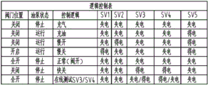
图4为逻辑控制表;Fig. 4 is a logic control table;
图5为螺旋旋转油缸示意图;Fig. 5 is a schematic diagram of a helical rotary oil cylinder;
图中:1.框架结构件;2.活塞式蓄能器;3.油压表;4.氮气压力表;5.压力开关A;6.压力开关B;7.油箱;8.慢开慢关快关阀块;9.螺旋旋转油缸;10.快插接头+球阀;11.接线盒;12.气体安全阀;13.压力开关C;14.气液增压泵;15.气压阀块;16.气动三联件电磁阀;17.高压过滤器;18.截止阀A;19.单向阀;20.截止阀B;21.溢流阀;22.二位三通电磁阀A;23.二位三通电磁阀B;24.液控单向阀A;25.液控单向阀B;26.截止阀C;27.截止阀D;28.逻辑阀A;29.截止阀E;30.充气阀;31.逻辑阀B;32.二位二通电磁阀A;33.二位二通电磁阀B;34.端盖;35.传动轴;36.活塞;37.齿套;38.行程限位块;39.导向套;40.适配器;41.缸筒。In the picture: 1. Frame structure; 2. Piston accumulator; 3. Oil pressure gauge; 4. Nitrogen pressure gauge; 5. Pressure switch A; 6. Pressure switch B; Shut-off valve block; 9. Screw rotary oil cylinder; 10. Quick plug connector + ball valve; 11. Junction box; 12. Gas safety valve; 13. Pressure switch C; 14. Gas-liquid booster pump; 15. Air pressure valve block ; 16. Pneumatic triple solenoid valve; 17. High pressure filter; 18. Globe valve A; 19. Check valve; 20. Globe valve B; 21. Relief valve; 22. Two-position three-way solenoid valve A; 23 .2-position 3-way solenoid valve B; 24. Hydraulic control check valve A; 25. Hydraulic control check valve B; 26. Globe valve C; 27. Globe valve D; 28. Logic valve A; 29.
具体实施方式Detailed ways
下面通过附图及具体实施方式对本发明作进一步说明。The present invention will be further described below through the accompanying drawings and specific embodiments.
螺旋旋转油缸快速关闭高压气液联动装置的核心部件安装在框架结构件1上,如图1给出了各个部件安装的示意图。The core components of the fast-closing high-pressure gas-liquid linkage device of the helical rotary oil cylinder are installed on the frame structure 1. Figure 1 shows the schematic diagram of the installation of each component.
框架结构件1的上下端为圆环状的法兰,上下法兰之间安装竖直的安装筋板,将法兰之间的空间均匀分割,同时也便于各个部件的安装。The upper and lower ends of the frame structure member 1 are annular flanges, and vertical mounting ribs are installed between the upper and lower flanges, which evenly divides the space between the flanges and facilitates the installation of various components.
其中,活塞式蓄能器2安装在上端的法兰上,油压表3和氮气压力表4通过筋板安装,且位于上下法兰之间,压力开关A5和压力开关B6安装在下法兰下表面,同时油箱5固定于上法兰下方,阀块8安装在下法兰上,螺旋旋转油缸9和快插接头球阀10安装在下法兰下方,接线盒11安装在筋板上。Among them, the piston accumulator 2 is installed on the upper flange, the
如图2所示,气体安全阀12固定在上法兰上,压力开关C13固定于筋板,气液增压泵14固定在下法兰上,气压阀块15和气动三联件电磁阀16均固定在筋板上。As shown in Figure 2, the
上述所有部件均与框架结构件2固定,各部件通过螺钉或螺栓螺母牢固地安装在这些筋板板或者法兰上,布置紧凑,使得整体体积较小。All the above components are fixed to the frame structure 2, and each component is firmly installed on these rib plates or flanges through screws or bolts and nuts, and the arrangement is compact, so that the overall volume is small.
上述只是各个部件的安装位置和方式,为了说明本装置的原理,有必要结合图3将各个器件的连接具体描述如下。The above is only the installation position and manner of each component. In order to explain the principle of the device, it is necessary to describe the connection of each component in detail as follows with reference to FIG. 3 .
如图3所示,螺旋旋转油缸快速关闭高压气液联动装置包括:As shown in Figure 3, the rapid closing of the high-pressure gas-liquid linkage device of the helical rotary oil cylinder includes:
与螺旋旋转油缸9通过管路连接的活塞式蓄能器2和油箱7、安装在螺旋旋转油缸9进油侧管路上的截止阀C26和逻辑阀A28、安装在螺旋旋转油缸9排油侧管路上的截止阀D27、逻辑阀B31,所述的油箱7和逻辑阀A28之间的管路上依次安装气液增压泵14、高压过滤器17、截止阀A18和单向阀19,且油箱7和逻辑阀A28之间的管路与活塞式蓄能器2连通。Piston accumulator 2 and
单向阀19后段的管路上安装截止阀B20。A stop valve B20 is installed on the pipeline behind the check valve 19.
气液增压泵14与气动三联件电磁阀16和快插接头球阀10依次连接,用于驱动上述阀结构。The gas-
在高压过滤器17、截止阀A18之间的管路上可以安装油压表3。The
在螺旋旋转油缸9进油侧和排油侧之间的管路上串联安装二位三通电磁阀A22和二位三通电磁阀B23,且在二位三通电磁阀A22和二位三通电磁阀B23之间的管路上安装压力开关A5和溢流阀21。Install the two-position three-way solenoid valve A22 and the two-position three-way solenoid valve B23 in series on the pipeline between the oil inlet side and the oil discharge side of the screw rotary oil cylinder 9, and install the two-position three-way solenoid valve A22 and the two-position three-way solenoid valve A22 in series. Pressure switch A5 and relief valve 21 are installed on the pipeline between valve B23.
二位三通电磁阀A22和二位三通电磁阀B23与螺旋旋转油缸9之间的管路上分别安装液控单向阀A24和液控单向阀B25。A hydraulically controlled check valve A24 and a hydraulically controlled check valve B25 are respectively installed on the pipeline between the two-position three-way solenoid valve A22 and the two-position three-way solenoid valve B23 and the helical rotary oil cylinder 9 .
活塞式蓄能器2的气侧安装截止阀E29和充气阀30,在充气管路上可以安装氮气压力表4、压力开关C13和气体安全阀12。A stop valve E29 and a
上述的逻辑阀A28和逻辑阀B31的作用是控制油的排出,通过连接二位二通电磁阀A32和二位二通电磁阀B33进行控制,两个二位二通电磁阀串联,需要将二位二通电磁阀A32和二位二通电磁阀B33同时通电,才能排出逻辑阀A28和逻辑阀B31的控制油,此种冗余设计可以降低误操作的风险。在串联管路上可以安装压力开关B6。The function of the above-mentioned logic valve A28 and logic valve B31 is to control the discharge of oil, which is controlled by connecting the two-position two-way solenoid valve A32 and the two-position two-way solenoid valve B33, and the two two-position two-way solenoid valves are connected in series. The two-position two-way solenoid valve A32 and the two-position two-way solenoid valve B33 are energized at the same time to discharge the control oil of the logic valve A28 and the logic valve B31. This redundant design can reduce the risk of misoperation. A pressure switch B6 can be installed on the series line.
在活塞式蓄能器2的气侧充指定量的氮气,再通过气液增压泵14对活塞式蓄能器2的油侧进行充油蓄压,利用压缩后的高压氮气充当永不失效的气弹簧,用作快关动作的能量源。相比传统的机械弹簧,气弹簧重量轻,且可大量次地使用不会失效。The gas side of the piston accumulator 2 is charged with a specified amount of nitrogen, and then the oil side of the piston accumulator 2 is charged with oil through the gas-
利用活塞式蓄能器2中的高压氮气储存能量,当进行快关动作时,高压氮气快速膨胀,通过活塞式蓄能器2中的活塞推动高压油经过逻辑阀28、截止阀26后,进入螺旋旋转油缸9的一侧,螺旋旋转油缸9另一侧的液压油经过截止阀27、逻辑阀B31后,排入油箱7。螺旋旋转油缸9进油侧的压力最大可达到蓄能器中高压氮气的压力,当压缩后的氮气压力足够高(目前25MPa),再适当增加螺旋旋转油缸9进油侧的作用面积,螺旋旋转油缸9即可输出很大的扭矩(可达10万NM)。The high-pressure nitrogen in the piston-type accumulator 2 is used to store energy. When the quick-closing action is performed, the high-pressure nitrogen gas expands rapidly, and the piston in the piston-type accumulator 2 pushes the high-pressure oil through the
如图3、图4所示,由于螺旋旋转油缸9的进油侧和排油侧均有逻辑阀A28和逻辑阀B31,在不进行快关动作时,蓄能器2中储存的高压油通过控制管路将逻辑阀28和31关闭,从而使系统的慢开和慢关通道与蓄能器2隔离。如此一来,在进行完一次快关动作之前,无需对蓄能器2进行反复蓄压,同时,执行器在做慢开动作时,仅仅需要克服阀门的负载,无需克服蓄能器2中的氮气压力。而且,在阀门处于开启位置时,执行器的螺旋旋转油缸9中只有很低的压力(0~2MPa左右),高压被封锁在仅存在于蓄能器2及其相关的管路中,从而降低了系统的泄漏风险。As shown in Fig. 3 and Fig. 4, since there are logic valve A28 and logic valve B31 on the oil inlet side and oil discharge side of the screw rotary cylinder 9, when the quick closing action is not performed, the high pressure oil stored in the accumulator 2 passes through The control line closes the
当蓄能器完成充油蓄压后,仅将二位二通电磁阀A32通电,高压油会使压力开关6报警,而执行器不发生快关,从而说明二位二通电磁阀A32能正常动作,二位二通电磁阀B33关闭到位,然后将二位二通电磁阀A32断电,二位二通电磁阀B33通电,压力开关B6复位,说明二位二通电磁阀B33能正常动作。这样就可以在执行器不进行快关动作的情况下,对二位二通电磁阀A32和二位二通电磁阀B33这两个决定快关功能的电磁阀进行在线检测。When the accumulator is filled with oil and pressure, only the two-position two-way solenoid valve A32 is energized, and the high-pressure oil will cause the
高压过滤器17、截止阀A18、单向阀19、截止阀B20、溢流阀21、二位三通电磁阀A22、二位三通电磁阀B23、液控单向阀A24、液控单向阀B25、截止阀C26、截止阀D27、逻辑阀A28、逻辑阀B31、二位二通电磁阀A32、二位二通电磁阀33均集成到慢开慢关快关阀块8中,截止阀E29、充气阀30集成到气压阀块15中。High pressure filter 17, globe valve A18, check valve 19, globe valve B20, relief valve 21, 2/3-way solenoid valve A22, 2/3-way solenoid valve B23, hydraulic control check valve A24, hydraulic control check valve Valve B25, globe valve C26, globe valve D27, logic valve A28, logic valve B31, two-position two-way solenoid valve A32, and two-position two-
如图4给出了阀门控制具体控制逻辑。Figure 4 shows the specific control logic of valve control.
如图5所示的螺旋旋转油缸9,由缸筒41、端盖34、活塞36、传动轴35组成。传动轴35端部加工有凸台,传动轴35端部安装适配器4,在上述凸台的一侧,传动轴35的外侧安装导向套39,导向套39通过凸台定位,同时在凸台的另一侧安装行程限位块38,其固定在缸筒41内,在活塞36外侧螺纹安装齿套37,行程其作为齿套37随活塞36运动的缓冲装置,减少快速关闭的碰撞力。As shown in FIG. 5 , the helical rotary oil cylinder 9 is composed of a
螺旋旋转油缸9作为该装置的输出端,工作压力为25MPa~30MPa,省去了拨叉箱体。液压和气动管路的布置比机械传动结构的布置灵活得多,从而使得零部件布局更为灵活,结构更为紧凑。The screw rotary oil cylinder 9 is used as the output end of the device, and the working pressure is 25MPa to 30MPa, and the fork box is omitted. The arrangement of hydraulic and pneumatic pipelines is much more flexible than the arrangement of mechanical transmission structures, which makes the layout of components more flexible and the structure more compact.
Claims (10)
Priority Applications (1)
| Application Number | Priority Date | Filing Date | Title |
|---|---|---|---|
| CN201811433755.5A CN111237268A (en) | 2018-11-28 | 2018-11-28 | Spiral rotary oil cylinder high-pressure gas-liquid linkage device capable of being quickly closed |
Applications Claiming Priority (1)
| Application Number | Priority Date | Filing Date | Title |
|---|---|---|---|
| CN201811433755.5A CN111237268A (en) | 2018-11-28 | 2018-11-28 | Spiral rotary oil cylinder high-pressure gas-liquid linkage device capable of being quickly closed |
Publications (1)
| Publication Number | Publication Date |
|---|---|
| CN111237268A true CN111237268A (en) | 2020-06-05 |
Family
ID=70863633
Family Applications (1)
| Application Number | Title | Priority Date | Filing Date |
|---|---|---|---|
| CN201811433755.5A Pending CN111237268A (en) | 2018-11-28 | 2018-11-28 | Spiral rotary oil cylinder high-pressure gas-liquid linkage device capable of being quickly closed |
Country Status (1)
| Country | Link |
|---|---|
| CN (1) | CN111237268A (en) |
Cited By (1)
| Publication number | Priority date | Publication date | Assignee | Title |
|---|---|---|---|---|
| CN114135710A (en) * | 2021-12-02 | 2022-03-04 | 大连大高阀门股份有限公司 | Hydraulic Control System of Gas-liquid Linkage Drive |
Citations (6)
| Publication number | Priority date | Publication date | Assignee | Title |
|---|---|---|---|---|
| GB1311645A (en) * | 1970-04-18 | 1973-03-28 | Daiei Kogyo Sha Kk | Hydraulic torque actuator |
| DE2924536A1 (en) * | 1979-06-19 | 1981-01-15 | Bollmann Hydraulik | Hinging spindle drive system - has balls in cage engaging between helical spindle teeth and in bearings in piston |
| CN2729468Y (en) * | 2004-08-25 | 2005-09-28 | 黄云平 | Energy storage electrohydraulic linkage actuator for quickly closing valve |
| CN205559405U (en) * | 2016-04-20 | 2016-09-07 | 正洲泵阀制造有限公司 | Oscillating hydraulic actuator |
| CN107044557A (en) * | 2016-12-30 | 2017-08-15 | 大连大高阀门股份有限公司 | Suitable for the gas-liquid linked drive device of main steam isolation valve |
| CN209523929U (en) * | 2018-11-28 | 2019-10-22 | 中核苏阀科技实业股份有限公司 | A kind of spiral rotating oil cylinder quick closedown high-pressure gas-liquid linkage |
-
2018
- 2018-11-28 CN CN201811433755.5A patent/CN111237268A/en active Pending
Patent Citations (6)
| Publication number | Priority date | Publication date | Assignee | Title |
|---|---|---|---|---|
| GB1311645A (en) * | 1970-04-18 | 1973-03-28 | Daiei Kogyo Sha Kk | Hydraulic torque actuator |
| DE2924536A1 (en) * | 1979-06-19 | 1981-01-15 | Bollmann Hydraulik | Hinging spindle drive system - has balls in cage engaging between helical spindle teeth and in bearings in piston |
| CN2729468Y (en) * | 2004-08-25 | 2005-09-28 | 黄云平 | Energy storage electrohydraulic linkage actuator for quickly closing valve |
| CN205559405U (en) * | 2016-04-20 | 2016-09-07 | 正洲泵阀制造有限公司 | Oscillating hydraulic actuator |
| CN107044557A (en) * | 2016-12-30 | 2017-08-15 | 大连大高阀门股份有限公司 | Suitable for the gas-liquid linked drive device of main steam isolation valve |
| CN209523929U (en) * | 2018-11-28 | 2019-10-22 | 中核苏阀科技实业股份有限公司 | A kind of spiral rotating oil cylinder quick closedown high-pressure gas-liquid linkage |
Cited By (2)
| Publication number | Priority date | Publication date | Assignee | Title |
|---|---|---|---|---|
| CN114135710A (en) * | 2021-12-02 | 2022-03-04 | 大连大高阀门股份有限公司 | Hydraulic Control System of Gas-liquid Linkage Drive |
| CN114135710B (en) * | 2021-12-02 | 2024-12-20 | 大连大高阀门股份有限公司 | Hydraulic control system of gas-hydraulic drive device |
Similar Documents
| Publication | Publication Date | Title |
|---|---|---|
| CN201100474Y (en) | Energy-storage electrolysis joint valve gate executor | |
| CN201391499Y (en) | Intelligent electrohydraulic actuating mechanism | |
| WO2021079288A4 (en) | Shock absorber assembly with adjustable height | |
| US7356990B2 (en) | Electro hydraulic actuator with spring energized accumulators | |
| JPH0854083A (en) | Valve drive | |
| CN209523929U (en) | A kind of spiral rotating oil cylinder quick closedown high-pressure gas-liquid linkage | |
| RU2350429C1 (en) | Gasostat | |
| CN219176697U (en) | Leather bag damage detection system of leather bag type energy accumulator | |
| US3718158A (en) | Accumulator control system | |
| CN111288207A (en) | A hydraulic control system for a straight-stroke gas-liquid linkage actuator | |
| CN103410808B (en) | Intrinsic safety type fire-proof and explosion-proof electro-hydraulic actuator and control method thereof | |
| CN212054829U (en) | High-pressure fire-resistant oil electrohydraulic control system of main steam pipeline quick closing valve of steam turbine | |
| CN114198347A (en) | Hydraulic control system of safety cut-off valve | |
| CN114135710A (en) | Hydraulic Control System of Gas-liquid Linkage Drive | |
| CN209398906U (en) | A kind of hydraulic control system of Direct Travel pneumatic hydraulic actuator | |
| CN1102233A (en) | Operating device for regulating valve | |
| KR102526159B1 (en) | High-capacity, low-noise type ultra-high pressure piston compressor hydraulic control system for hydrogen filling stations | |
| CN201112259Y (en) | Hydraulic Integrated Operating Mechanism for High Voltage Circuit Breaker | |
| CN111623002A (en) | Multipurpose emergency power unit | |
| US20070113899A1 (en) | Compact manifolded fail safe hydraulic control system | |
| CN210106275U (en) | Electro-hydraulic actuating system of thrust valve | |
| RU2255250C1 (en) | Pneumatic drive with jet motor for shutoff and control valves and electropneumatic control device | |
| CN204755306U (en) | Vortex hydraulic pump and have its gas -liquid linkage actuating mechanism | |
| JP3439656B2 (en) | Switchgear for pneumatically operated on-off valves | |
| CN114060331B (en) | Column type hydraulic bidirectional propulsion locking device |
Legal Events
| Date | Code | Title | Description |
|---|---|---|---|
| PB01 | Publication | ||
| PB01 | Publication | ||
| SE01 | Entry into force of request for substantive examination | ||
| SE01 | Entry into force of request for substantive examination | ||
| RJ01 | Rejection of invention patent application after publication | ||
| RJ01 | Rejection of invention patent application after publication |
Application publication date: 20200605 |