CN111237280A - Rigidity-adjustable corner self-servo valve control hydraulic joint - Google Patents
Rigidity-adjustable corner self-servo valve control hydraulic joint Download PDFInfo
- Publication number
- CN111237280A CN111237280A CN202010219778.7A CN202010219778A CN111237280A CN 111237280 A CN111237280 A CN 111237280A CN 202010219778 A CN202010219778 A CN 202010219778A CN 111237280 A CN111237280 A CN 111237280A
- Authority
- CN
- China
- Prior art keywords
- working chamber
- valve core
- pressure relief
- cavity
- floating
- Prior art date
- Legal status (The legal status is an assumption and is not a legal conclusion. Google has not performed a legal analysis and makes no representation as to the accuracy of the status listed.)
- Granted
Links
- 238000007667 floating Methods 0.000 claims abstract description 55
- 238000007789 sealing Methods 0.000 claims description 6
- 230000000149 penetrating effect Effects 0.000 claims 1
- 238000010586 diagram Methods 0.000 description 3
- 238000009434 installation Methods 0.000 description 3
- 238000000034 method Methods 0.000 description 2
- 206010023230 Joint stiffness Diseases 0.000 description 1
- 230000009286 beneficial effect Effects 0.000 description 1
- 239000008358 core component Substances 0.000 description 1
- 238000005516 engineering process Methods 0.000 description 1
- 238000009776 industrial production Methods 0.000 description 1
- 238000003801 milling Methods 0.000 description 1
Images


Classifications
-
- F—MECHANICAL ENGINEERING; LIGHTING; HEATING; WEAPONS; BLASTING
- F15—FLUID-PRESSURE ACTUATORS; HYDRAULICS OR PNEUMATICS IN GENERAL
- F15B—SYSTEMS ACTING BY MEANS OF FLUIDS IN GENERAL; FLUID-PRESSURE ACTUATORS, e.g. SERVOMOTORS; DETAILS OF FLUID-PRESSURE SYSTEMS, NOT OTHERWISE PROVIDED FOR
- F15B13/00—Details of servomotor systems ; Valves for servomotor systems
- F15B13/02—Fluid distribution or supply devices characterised by their adaptation to the control of servomotors
- F15B13/04—Fluid distribution or supply devices characterised by their adaptation to the control of servomotors for use with a single servomotor
-
- F—MECHANICAL ENGINEERING; LIGHTING; HEATING; WEAPONS; BLASTING
- F15—FLUID-PRESSURE ACTUATORS; HYDRAULICS OR PNEUMATICS IN GENERAL
- F15B—SYSTEMS ACTING BY MEANS OF FLUIDS IN GENERAL; FLUID-PRESSURE ACTUATORS, e.g. SERVOMOTORS; DETAILS OF FLUID-PRESSURE SYSTEMS, NOT OTHERWISE PROVIDED FOR
- F15B15/00—Fluid-actuated devices for displacing a member from one position to another; Gearing associated therewith
- F15B15/08—Characterised by the construction of the motor unit
- F15B15/14—Characterised by the construction of the motor unit of the straight-cylinder type
- F15B15/1423—Component parts; Constructional details
-
- F—MECHANICAL ENGINEERING; LIGHTING; HEATING; WEAPONS; BLASTING
- F15—FLUID-PRESSURE ACTUATORS; HYDRAULICS OR PNEUMATICS IN GENERAL
- F15B—SYSTEMS ACTING BY MEANS OF FLUIDS IN GENERAL; FLUID-PRESSURE ACTUATORS, e.g. SERVOMOTORS; DETAILS OF FLUID-PRESSURE SYSTEMS, NOT OTHERWISE PROVIDED FOR
- F15B2215/00—Fluid-actuated devices for displacing a member from one position to another
- F15B2215/30—Constructional details thereof
Landscapes
- Engineering & Computer Science (AREA)
- Physics & Mathematics (AREA)
- Fluid Mechanics (AREA)
- Mechanical Engineering (AREA)
- General Engineering & Computer Science (AREA)
- Actuator (AREA)
Abstract
本发明涉及一种刚度可调的转角自伺服阀控液压关节,本发明提供的液压关节中当第一工作腔/第二工作腔内压力大于阈值时浮动阀芯下行并使第一卸压流道通过第三卸压流道与第二卸压流道连通,第一工作腔/第二工作腔内高液压流入第二工作腔/第一工作腔内;当第一工作腔/第二工作腔内压力下降并恢复至阈值时浮动阀芯上行并复位,第一工作腔/第二工作腔内高压油停止流入第二工作腔/第一工作腔内。本发明中通过浮动阀芯的浮动以实现第一卸压流道及第二卸压流道的通/断,从而控制高压腔压力油是否向低压腔卸荷并改变关节刚度。
The invention relates to a self-servo valve-controlled hydraulic joint with adjustable stiffness. In the hydraulic joint provided by the invention, when the pressure in the first working chamber/the second working chamber is greater than a threshold value, the floating valve core descends and makes the first pressure relief flow The third pressure relief channel is communicated with the second pressure relief channel, and the high hydraulic pressure in the first working chamber/second working chamber flows into the second working chamber/first working chamber; when the first working chamber/second working chamber When the pressure in the cavity drops and returns to the threshold value, the floating spool moves upward and resets, and the high-pressure oil in the first working cavity/second working cavity stops flowing into the second working cavity/first working cavity. In the present invention, the on/off of the first pressure relief channel and the second pressure relief channel is realized by the floating of the floating valve core, so as to control whether the pressure oil in the high pressure chamber is unloaded to the low pressure chamber and change the stiffness of the joint.
Description
技术领域technical field
本发明涉及一种液压关节,尤其涉及一种刚度可调的转角自伺服阀控液压关节。The invention relates to a hydraulic joint, in particular to a rotational angle self-servo valve-controlled hydraulic joint with adjustable stiffness.
背景技术Background technique
液压转角伺服技术的工作原理是利用电机的小力矩直接驱动阀芯使阀口打开,从而让高压油推动阀体转动,并进而得到大输出力矩。The working principle of hydraulic angle servo technology is to use the small torque of the motor to directly drive the valve core to open the valve port, so that the high-pressure oil can push the valve body to rotate, and then obtain a large output torque.
液压转角自伺服阀是液压控制系统中的核心元件,其具有精度高、反应快的特点,在高精度的机电一体化系统、航空航天机载驱动系统、大型试验设备中有着广泛的应用,因而得到国内外科技人员的关注。The hydraulic angle self-servo valve is the core component of the hydraulic control system. It has the characteristics of high precision and fast response. It is widely used in high-precision mechatronic systems, aerospace airborne drive systems, and large-scale test equipment. Therefore, Get the attention of domestic and foreign scientific and technological personnel.
目前,输出力矩较大的液压机械臂类机器人在工业生产中有广泛应用,但该类机器人的人机接触安全性较差,不具有在意外接触瞬间对接触进行处理的能力,这是一个急需解决的难题。At present, hydraulic manipulator robots with large output torque are widely used in industrial production, but such robots have poor human-machine contact safety and do not have the ability to handle contact at the moment of accidental contact, which is an urgent need. problem solved.
发明内容SUMMARY OF THE INVENTION
针对上述问题,现提供一种刚度可调且可实现过载保护的的转角自伺服阀控液压关节。In view of the above problems, a self-servo valve-controlled hydraulic joint with adjustable stiffness and overload protection is provided.
具体技术方案如下:The specific technical solutions are as follows:
一种刚度可调的转角自伺服阀控液压关节,包括缸体、左端盖、右端盖、驱动舵机、缸体内圈、外阀体、固定挡块、叶片、内阀体、阀芯、阀体转轴及法兰盘,缸体的两端分别由左端盖及右端盖密封并形成密封腔体,缸体及外阀体均设于上述密封腔体内,内阀体穿设于缸体内圈及外阀体之间,阀芯设于内阀体内,且阀芯的一端穿过左端盖并与驱动舵机的舵机盘连接,阀体转轴的一端连接于内阀体上,阀体转轴的另一端穿过右端盖并与法兰盘连接,叶片及固定挡块设于缸体内圈及外阀体之间,且叶片固定连接于内阀体的外壁上,固定挡块连接于缸体的内壁上,且固定挡块及叶片将缸体、内阀体、缸体内圈及外阀体合围形成的密封腔分隔形成第一工作腔、第二工作腔,具有这样的特征,固定挡块内设有浮动阀芯腔、第一卸压流道及第二卸压流道,第一卸压流道及第二卸压流道的一端均与浮动阀芯腔连通,第一卸压流道及第二卸压流道的的另一端分别对应与第一工作腔、第二工作腔连通,浮动阀芯腔内设有浮动阀芯,浮动阀芯滑动密封于浮动阀芯腔内,且浮动阀芯内设有第三卸压流道;An angle self-servo valve-controlled hydraulic joint with adjustable stiffness, comprising a cylinder body, a left end cover, a right end cover, a driving steering gear, a cylinder inner ring, an outer valve body, a fixed stop, a blade, an inner valve body, a valve core, The shaft of the valve body and the flange plate, the two ends of the cylinder body are sealed by the left end cover and the right end cover respectively and form a sealing cavity, the cylinder body and the outer valve body are all set in the above-mentioned sealing cavity, and the inner valve body is penetrated in the cylinder body. Between the ring and the outer valve body, the valve core is set in the inner valve body, and one end of the valve core passes through the left end cover and is connected with the steering gear plate that drives the steering gear, and one end of the valve body shaft is connected to the inner valve body. The other end of the rotating shaft passes through the right end cover and is connected with the flange plate, the vane and the fixed stopper are arranged between the inner ring of the cylinder and the outer valve body, and the vane is fixedly connected to the outer wall of the inner valve body, and the fixed stopper is connected to the On the inner wall of the cylinder body, the fixed block and the vanes separate the sealing cavity formed by the cylinder body, the inner valve body, the inner ring of the cylinder and the outer valve body to form the first working chamber and the second working chamber, which has the following characteristics: The fixed block is provided with a floating valve core cavity, a first pressure relief flow channel and a second pressure relief flow channel. One end of the first pressure relief flow channel and the second pressure relief flow channel is connected with the floating valve core cavity. The other ends of the pressure relief flow channel and the second pressure relief flow channel are respectively communicated with the first working chamber and the second working chamber. The floating valve core cavity is provided with a floating valve core, and the floating valve core is slidably sealed in the floating valve core cavity. Inside, and the floating valve core is provided with a third pressure relief channel;
其中,当第一工作腔/第二工作腔内压力大于阈值时浮动阀芯下行并使第一卸压流道通过第三卸压流道与第二卸压流道连通,第一工作腔/第二工作腔内高液压流入第二工作腔/第一工作腔内;当第一工作腔/第二工作腔内压力下降并恢复至阈值时浮动阀芯上行并复位,第一工作腔/第二工作腔内高压油停止流入第二工作腔/第一工作腔内。Wherein, when the pressure in the first working chamber/second working chamber is greater than the threshold value, the floating spool goes down and makes the first pressure relief flow passage communicate with the second pressure relief flow passage through the third pressure relief flow passage, and the first working chamber/ The high hydraulic pressure in the second working chamber flows into the second working chamber/the first working chamber; when the pressure in the first working chamber/the second working chamber drops and returns to the threshold value, the floating spool moves up and resets, and the first working chamber/the first working chamber The high-pressure oil in the second working chamber stops flowing into the second working chamber/first working chamber.
上述的转角自伺服阀控液压关节,还具有这样的特征,液压关节还包括第一复位簧、第二复位簧及设于缸体上的外接接头,外接接头内设有油液流道,且外接接头通过油液流道与浮动阀芯腔连通,第一复位簧及第二复位簧均设于浮动阀芯腔内,且浮动阀芯的一端通过第一复位簧连接于外接接头上,浮动阀芯的另一端通过第二复位簧连接于固定挡块上。The above-mentioned rotary angle self-servo valve-controlled hydraulic joint also has the feature that the hydraulic joint further includes a first return spring, a second return spring and an external joint arranged on the cylinder body, and the external joint is provided with an oil flow channel, and The external joint is communicated with the floating valve core cavity through the oil flow channel, the first return spring and the second return spring are both arranged in the floating valve core cavity, and one end of the floating valve core is connected to the external joint through the first return spring, floating The other end of the valve core is connected to the fixed block through a second return spring.
上述的转角自伺服阀控液压关节,还具有这样的特征,固定挡块内还设有一端与浮动阀芯腔连通的第四卸压流道,第四卸压流道的另一端通过位于缸体内的连接流道与位于左端盖上的第一卸油接头连通。The above-mentioned rotary angle self-servo valve-controlled hydraulic joint also has the feature that the fixed stop is further provided with a fourth pressure relief flow channel, one end of which is communicated with the floating valve core cavity, and the other end of the fourth pressure relief flow channel passes through the cylinder located in the cylinder. The connecting flow channel in the body communicates with the first oil discharge joint located on the left end cover.
上述的转角自伺服阀控液压关节,还具有这样的特征,固定挡块与缸体内壁的接触面上设有安装通孔,且缸体上设有与安装于安装通孔内的固定螺钉相配合的沉孔,固定挡块通过固定螺钉配合安装于缸体上。The above-mentioned rotary angle self-servo valve-controlled hydraulic joint also has the feature that a mounting through hole is provided on the contact surface between the fixed stopper and the inner wall of the cylinder, and the cylinder body is provided with a fixing screw installed in the mounting through hole. The matching countersunk hole and the fixed block are installed on the cylinder body through the fixing screw.
上述方案的有益效果是:The beneficial effects of the above scheme are:
本发明中通过浮动阀芯的浮动以实现第一卸压流道及第二卸压流道的通/断,从而控制高压腔压力油是否向低压腔卸荷并改变关节刚度。In the present invention, the on/off of the first pressure relief channel and the second pressure relief channel is realized by the floating of the floating valve core, so as to control whether the pressure oil in the high pressure chamber is unloaded to the low pressure chamber and change the stiffness of the joint.
附图说明Description of drawings
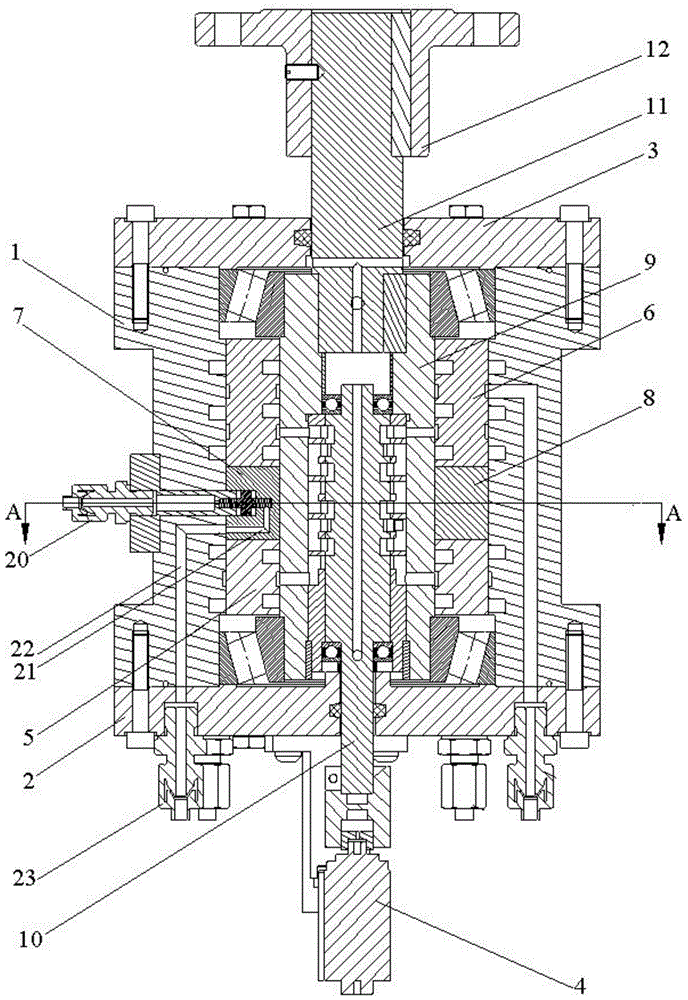
图1为本发明的实施例中提供的转角自伺服阀控液压关节的剖视结构示意图;1 is a schematic cross-sectional structural diagram of a rotary angle self-servo valve-controlled hydraulic joint provided in an embodiment of the present invention;
图2为图1中沿字母A-A线处的剖视结构示意图;Fig. 2 is the sectional structure schematic diagram along the letter A-A line in Fig. 1;
图3为本发明的实施例中提供的转角自伺服阀控液压关节的部分分解结构示意图;3 is a schematic diagram of a partially exploded structure of a rotary angle self-servo valve-controlled hydraulic joint provided in an embodiment of the present invention;
图4为图3中字母A处对应部分的局部放大图。FIG. 4 is a partial enlarged view of the part corresponding to the letter A in FIG. 3 .
附图中:1、缸体;2、左端盖;3、右端盖;4、驱动舵机;5、缸体内圈;6、外阀体;7、固定挡块;8、叶片;9、内阀体;10、阀芯;11、阀体转轴;12、法兰盘;13、浮动阀芯腔;14、第一卸压流道;15、第二卸压流道;16、浮动阀芯;17、第三卸压流道;18、第一复位簧;19、第二复位簧;20、外接接头;21、第四卸压流道;22、连接流道;23、第一卸油接头;24、固定螺钉;25、第一工作腔;26、第二工作腔。In the drawings: 1. Cylinder block; 2. Left end cover; 3. Right end cover; 4. Driving steering gear; 5. Cylinder inner ring; 6. Outer valve body; 7. Fixed stop; 8. Blade; 9. Inner valve body; 10, valve core; 11, valve body shaft; 12, flange plate; 13, floating valve core cavity; 14, first pressure relief channel; 15, second pressure relief channel; 16, floating valve Core; 17, the third pressure relief flow channel; 18, the first return spring; 19, the second return spring; 20, the external joint; 21, the fourth pressure relief flow channel; 22, the connection flow channel; 23, the first release oil joint; 24, fixing screw; 25, first working chamber; 26, second working chamber.
具体实施方式Detailed ways
下面将结合本发明实施例中的附图,对本发明实施例中的技术方案进行清楚、完整地描述,显然,所描述的实施例仅仅是本发明一部分实施例,而不是全部的实施例。基于本发明中的实施例,本领域普通技术人员在没有作出创造性劳动的前提下所获得的所有其他实施例,都属于本发明保护的范围。The technical solutions in the embodiments of the present invention will be clearly and completely described below with reference to the accompanying drawings in the embodiments of the present invention. Obviously, the described embodiments are only a part of the embodiments of the present invention, but not all of the embodiments. Based on the embodiments of the present invention, all other embodiments obtained by those of ordinary skill in the art without creative work fall within the protection scope of the present invention.
需要说明的是,在不冲突的情况下,本发明中的实施例及实施例中的特征可以相互组合。It should be noted that the embodiments of the present invention and the features of the embodiments may be combined with each other under the condition of no conflict.
下面结合附图和具体实施例对本发明作进一步说明,但不作为本发明的限定。The present invention will be further described below with reference to the accompanying drawings and specific embodiments, but it is not intended to limit the present invention.
如图1至图4所示,本发明的实施例中提供的转角自伺服阀控液压关节包括缸体1、左端盖2、右端盖3、驱动舵机4、缸体内圈5、外阀体6、固定挡块7、叶片8、内阀体9、阀芯10、阀体转轴11及法兰盘12,缸体1的两端分别由左端盖2及右端盖3密封并形成密封腔体,缸体内圈5及外阀体6均设于上述密封腔体内,内阀体9穿设于缸体内圈5及外阀体6之间,阀芯10设于内阀体9内,且阀芯10的一端穿过左端盖2并与驱动舵机4的舵机盘连接,阀体转轴11的一端连接于内阀体9上,阀体转轴11的另一端穿过右端盖3并与法兰盘12连接,叶片8及固定挡块7设于缸体内圈5及外阀体6之间,且叶片8固定连接于内阀体9的外壁上,固定挡块7连接于缸体1的内壁上,且固定挡块7及叶片8将缸体1、内阀体9、缸体内圈5及外阀体6合围形成的环状密封腔分隔形成第一工作腔25、第二工作腔26,本发明中固定挡块7内设有浮动阀芯腔13、第一卸压流道14及第二卸压流道15,第一卸压流道14及第二卸压流道15的一端均与浮动阀芯腔13连通,第一卸压流道14及第二卸压流道15的的另一端分别对应与第一工作腔25、第二工作腔26连通,浮动阀芯腔13内设有浮动阀芯16,浮动阀芯16滑动密封于浮动阀芯腔13内,且浮动阀芯16内设有第三卸压流道17。As shown in FIGS. 1 to 4 , the angle self-servo valve-controlled hydraulic joint provided in the embodiment of the present invention includes a cylinder block 1 , a
不同于现有技术,本发明中当第一工作腔25/第二工作腔26内压力大于阈值时浮动阀芯16下行并使第一卸压流道14通过第三卸压流道17与第二卸压流道15连通,第一工作腔25/第二工作腔26内高液压流入第二工作腔26/第一工作腔25内,从而实现高压腔压力油向低压腔卸荷,并进而改变关节刚度;当第一工作腔25/第二工作腔26内压力下降并恢复至阈值时浮动阀芯16上行并复位,第一工作腔25/第二工作腔26内高压油停止流入第二工作腔26/第一工作腔25内,此时液压关节即如同现有技术中提供的液压关节一般正常运转。Different from the prior art, in the present invention, when the pressure in the
本发明提供的液压关节正常运转时其工作原理与现有技术特别是本课题组研究、提供的液压关节(如申请号为CN201822233651.1、发明名称为“一种易于加工的液压转角自伺服柔顺驱动器”的实用新型专利)工作原理相同,因而本申请中不再对本申请提供的液压关节的工作原理做进一步赘述。When the hydraulic joint provided by the present invention operates normally, its working principle is the same as that of the prior art, especially the hydraulic joint researched and provided by this research group (for example, the application number is CN201822233651.1, and the name of the invention is "an easy-to-process hydraulic angle self-servo compliance"). The working principle of the hydraulic joint provided in this application is the same, so the working principle of the hydraulic joint provided in this application will not be further described in this application.
具体的,本发明提供的液压关节中还包括第一复位簧18、第二复位簧19及设于缸体1上的外接接头20,本发明中外接接头20内设有油液流道,且外接接头20通过油液流道与浮动阀芯腔13连通,且第一复位簧18及第二复位簧19均设于浮动阀芯腔13内,浮动阀芯16的一端通过第一复位簧18连接于外接接头20上,浮动阀芯16的另一端通过第二复位簧19连接于固定挡块7上,本发明中当第一工作腔25/第二工作腔26内压力大于阈值时即可通过外接接头20向浮动阀芯腔13中流入高压油,此时浮动阀芯16即可在高压油作用下下行并使第一卸压流道14通过第三卸压流道17与第二卸压流道15连通,从而使第一工作腔25/第二工作腔26内高液压流入第二工作腔26/第一工作腔25内;当第一工作腔25/第二工作腔26内压力下降并恢复至阈值时即可从浮动阀芯腔13内泵出高压油,此时浮动阀芯16即可在第一复位簧18及第二复位簧19作用下上行并复位,从而使第一卸压流道14与第二卸压流道15隔断,并进而使第一工作腔25/第二工作腔26内高液压停止流入第二工作腔26/第一工作腔25内,此时液压关节即可正常运转。Specifically, the hydraulic joint provided by the present invention further includes a
于上述技术方案基础上,进一步的,本实施例提供的液压关节中固定挡块7内还设有一端与浮动阀芯腔13连通的第四卸压流道21,本实施例中第四卸压流道21的另一端通过位于缸体1内的连接流道22与位于左端盖2上的第一卸油接头23连通,本实施例中考虑到滑动密封于浮动阀芯腔13内的浮动阀芯16随运转时间的增加密封性会有所降低,故通过设置第四卸压流道21及对应设置的连接流道使得渗入浮动阀芯腔13底部的油液可及时泵出。On the basis of the above technical solution, further, the fixed
于上述技术方案基础上,更进一步的,本实施例提供的液压关节中固定挡块7与缸体1内壁的接触面上设有安装通孔,且缸体1上设有与安装于安装通孔内的固定螺钉相配合的沉孔,本发明中固定挡块7通过固定螺钉24配合安装于缸体1上,不同于本课题组之前提供的液压关节,本发明中固定螺钉24从固定挡块7中穿出后再打进缸体1上的沉孔中,即可借助固定螺钉24的螺钉头与沉孔间的接触作用将固定挡块7有效紧固于缸体1上,且上述结构的改变还可避免现有技术中因在缸体1上开设安装通孔而导致空间受限而难以在缸体1上铣出与外接接头20及浮动阀芯腔13相配合的连接流道这一技术问题。On the basis of the above technical solutions, further, in the hydraulic joint provided by this embodiment, the contact surface between the
以上仅为本发明较佳的实施例,并非因此限制本发明的实施方式及保护范围,对于本领域技术人员而言,应当能够意识到凡运用本发明说明书及图示内容所作出的等同替换和显而易见的变化所得到的方案,均应当包含在本发明的保护范围内。The above are only preferred embodiments of the present invention, and are not intended to limit the embodiments and protection scope of the present invention. For those skilled in the art, they should be aware of the equivalent replacement and Solutions obtained by obvious changes shall all be included in the protection scope of the present invention.
Claims (4)
Priority Applications (1)
| Application Number | Priority Date | Filing Date | Title |
|---|---|---|---|
| CN202010219778.7A CN111237280B (en) | 2020-03-25 | 2020-03-25 | A Rotary Angle Self-Servo-Valve Controlled Hydraulic Joint with Adjustable Stiffness |
Applications Claiming Priority (1)
| Application Number | Priority Date | Filing Date | Title |
|---|---|---|---|
| CN202010219778.7A CN111237280B (en) | 2020-03-25 | 2020-03-25 | A Rotary Angle Self-Servo-Valve Controlled Hydraulic Joint with Adjustable Stiffness |
Publications (2)
| Publication Number | Publication Date |
|---|---|
| CN111237280A true CN111237280A (en) | 2020-06-05 |
| CN111237280B CN111237280B (en) | 2021-09-24 |
Family
ID=70867588
Family Applications (1)
| Application Number | Title | Priority Date | Filing Date |
|---|---|---|---|
| CN202010219778.7A Active CN111237280B (en) | 2020-03-25 | 2020-03-25 | A Rotary Angle Self-Servo-Valve Controlled Hydraulic Joint with Adjustable Stiffness |
Country Status (1)
| Country | Link |
|---|---|
| CN (1) | CN111237280B (en) |
Cited By (1)
| Publication number | Priority date | Publication date | Assignee | Title |
|---|---|---|---|---|
| CN113263521A (en) * | 2021-06-28 | 2021-08-17 | 武汉科技大学 | Multi-stage rigidity-adjustable passive flexible swing joint |
Citations (10)
| Publication number | Priority date | Publication date | Assignee | Title |
|---|---|---|---|---|
| JPH08295136A (en) * | 1994-07-20 | 1996-11-12 | Applied Power Inc | Liquid circuit |
| JPH0930267A (en) * | 1994-07-20 | 1997-02-04 | Applied Power Inc | Liquid circuit |
| CN102078228A (en) * | 2010-12-30 | 2011-06-01 | 霍启英 | Intelligent mechanical leg |
| CN103552089A (en) * | 2013-10-22 | 2014-02-05 | 北京航空航天大学 | Series-parallel connection ball joint device |
| CN104179746A (en) * | 2014-08-15 | 2014-12-03 | 武汉科技大学 | Self-servo hydraulic robot joint capable of continuously rotating |
| CN105067465A (en) * | 2015-08-04 | 2015-11-18 | 中国矿业大学 | Double-moving-platform parallel bionic hip joint testing machine and testing method thereof |
| CN105904480A (en) * | 2016-05-30 | 2016-08-31 | 广东工业大学 | Hydraulic joint |
| CN205852828U (en) * | 2016-05-30 | 2017-01-04 | 广东工业大学 | A kind of hydraulic knuckle |
| CN108161979A (en) * | 2018-02-12 | 2018-06-15 | 西安正安环境技术有限公司 | Robot hydraulic knuckle |
| CN109483589A (en) * | 2018-12-28 | 2019-03-19 | 武汉科技大学 | A kind of hydraulic corner easy to process is from the submissive driver of servo |
-
2020
- 2020-03-25 CN CN202010219778.7A patent/CN111237280B/en active Active
Patent Citations (10)
| Publication number | Priority date | Publication date | Assignee | Title |
|---|---|---|---|---|
| JPH08295136A (en) * | 1994-07-20 | 1996-11-12 | Applied Power Inc | Liquid circuit |
| JPH0930267A (en) * | 1994-07-20 | 1997-02-04 | Applied Power Inc | Liquid circuit |
| CN102078228A (en) * | 2010-12-30 | 2011-06-01 | 霍启英 | Intelligent mechanical leg |
| CN103552089A (en) * | 2013-10-22 | 2014-02-05 | 北京航空航天大学 | Series-parallel connection ball joint device |
| CN104179746A (en) * | 2014-08-15 | 2014-12-03 | 武汉科技大学 | Self-servo hydraulic robot joint capable of continuously rotating |
| CN105067465A (en) * | 2015-08-04 | 2015-11-18 | 中国矿业大学 | Double-moving-platform parallel bionic hip joint testing machine and testing method thereof |
| CN105904480A (en) * | 2016-05-30 | 2016-08-31 | 广东工业大学 | Hydraulic joint |
| CN205852828U (en) * | 2016-05-30 | 2017-01-04 | 广东工业大学 | A kind of hydraulic knuckle |
| CN108161979A (en) * | 2018-02-12 | 2018-06-15 | 西安正安环境技术有限公司 | Robot hydraulic knuckle |
| CN109483589A (en) * | 2018-12-28 | 2019-03-19 | 武汉科技大学 | A kind of hydraulic corner easy to process is from the submissive driver of servo |
Cited By (1)
| Publication number | Priority date | Publication date | Assignee | Title |
|---|---|---|---|---|
| CN113263521A (en) * | 2021-06-28 | 2021-08-17 | 武汉科技大学 | Multi-stage rigidity-adjustable passive flexible swing joint |
Also Published As
| Publication number | Publication date |
|---|---|
| CN111237280B (en) | 2021-09-24 |
Similar Documents
| Publication | Publication Date | Title |
|---|---|---|
| US11434938B2 (en) | Hydraulically driven joint for robot | |
| US8439640B2 (en) | Propeller blade pitch control system | |
| CN107116572B (en) | A kind of passive follow-up hydraulic robot revolute joint | |
| US8726787B2 (en) | Rotary hydraulic actuator with hydraulically controlled position limits | |
| CN106737827B (en) | Corner self-servo passive flexible hydraulic robot joint | |
| CN105545863B (en) | A kind of water hydraulic single blade formula oscillating cylinder | |
| US20150041689A1 (en) | Fluid-Actuated Butterfly Valve | |
| CN104747365A (en) | Hydraulic swing motor | |
| CN111237280A (en) | Rigidity-adjustable corner self-servo valve control hydraulic joint | |
| EP3868653A1 (en) | Rotary actuator | |
| CN102691614B (en) | Double-stator swing hydraulic multi-speed motor | |
| CN113263521A (en) | Multi-stage rigidity-adjustable passive flexible swing joint | |
| CN108386405A (en) | Robot dedicated hydraulic servo motor | |
| CN108953276B (en) | Screw thread cartridge type rotary direct-drive electrohydraulic servo valve with harmonic speed reducer | |
| CN208634124U (en) | Threaded Cartridge Rotary Direct Drive Electro-hydraulic Servo Valve | |
| CN108757619B (en) | Screw thread plug-in type rotary direct-drive electrohydraulic servo valve | |
| CN107035611A (en) | A kind of small size multiple-blade servo oscillating motor | |
| CN206510062U (en) | A kind of corner is from the submissive swinging driver of servo-hydraulic | |
| CN1986332A (en) | Directly driven volume controlled electro-hydraulic servo rotating-vane helm | |
| CN209458197U (en) | A kind of axial force balance structure of single-stage magnetic centrifugal pump | |
| CN113309698A (en) | Multi-component fluid proportional controller | |
| CN116696883A (en) | Miniature hydraulic blade swing motor | |
| CN106989050A (en) | A kind of Hydrodynamic float mechanical pump | |
| CN202468152U (en) | Cycloid hydraulic motor rotor and stator pair with sealing structure | |
| CN108506268A (en) | Limited pivot angle rotating hydraulic actuator with integrated sealing structure |
Legal Events
| Date | Code | Title | Description |
|---|---|---|---|
| PB01 | Publication | ||
| PB01 | Publication | ||
| SE01 | Entry into force of request for substantive examination | ||
| SE01 | Entry into force of request for substantive examination | ||
| GR01 | Patent grant | ||
| GR01 | Patent grant |