CN111237335A - Linear slide - Google Patents

Linear slide Download PDF

Info

Publication number
CN111237335A
CN111237335A CN201811493377.XA CN201811493377A CN111237335A CN 111237335 A CN111237335 A CN 111237335A CN 201811493377 A CN201811493377 A CN 201811493377A CN 111237335 A CN111237335 A CN 111237335A
Authority
CN
China
Prior art keywords
slider
strip
linear slide
slide rail
grooves
Prior art date
Legal status (The legal status is an assumption and is not a legal conclusion. Google has not performed a legal analysis and makes no representation as to the accuracy of the status listed.)
Granted
Application number
CN201811493377.XA
Other languages
Chinese (zh)
Other versions
CN111237335B (en
Inventor
张若轩
罗致杰
林志昌
Current Assignee (The listed assignees may be inaccurate. Google has not performed a legal analysis and makes no representation or warranty as to the accuracy of the list.)
Ome Technology Co Ltd
Original Assignee
Ome Technology Co Ltd
Priority date (The priority date is an assumption and is not a legal conclusion. Google has not performed a legal analysis and makes no representation as to the accuracy of the date listed.)
Filing date
Publication date
Application filed by Ome Technology Co Ltd filed Critical Ome Technology Co Ltd
Publication of CN111237335A publication Critical patent/CN111237335A/en
Application granted granted Critical
Publication of CN111237335B publication Critical patent/CN111237335B/en
Active legal-status Critical Current
Anticipated expiration legal-status Critical

Links

Images

Classifications

    • FMECHANICAL ENGINEERING; LIGHTING; HEATING; WEAPONS; BLASTING
    • F16ENGINEERING ELEMENTS AND UNITS; GENERAL MEASURES FOR PRODUCING AND MAINTAINING EFFECTIVE FUNCTIONING OF MACHINES OR INSTALLATIONS; THERMAL INSULATION IN GENERAL
    • F16CSHAFTS; FLEXIBLE SHAFTS; ELEMENTS OR CRANKSHAFT MECHANISMS; ROTARY BODIES OTHER THAN GEARING ELEMENTS; BEARINGS
    • F16C29/00Bearings for parts moving only linearly
    • F16C29/04Ball or roller bearings
    • F16C29/06Ball or roller bearings in which the rolling bodies circulate partly without carrying load
    • F16C29/0614Ball or roller bearings in which the rolling bodies circulate partly without carrying load with a shoe type bearing body, e.g. a body facing one side of the guide rail or track only
    • F16C29/0621Ball or roller bearings in which the rolling bodies circulate partly without carrying load with a shoe type bearing body, e.g. a body facing one side of the guide rail or track only for supporting load in essentially two directions, e.g. by multiple points of contact or two rows of rolling elements
    • F16C29/0623Ball or roller bearings in which the rolling bodies circulate partly without carrying load with a shoe type bearing body, e.g. a body facing one side of the guide rail or track only for supporting load in essentially two directions, e.g. by multiple points of contact or two rows of rolling elements with balls
    • FMECHANICAL ENGINEERING; LIGHTING; HEATING; WEAPONS; BLASTING
    • F16ENGINEERING ELEMENTS AND UNITS; GENERAL MEASURES FOR PRODUCING AND MAINTAINING EFFECTIVE FUNCTIONING OF MACHINES OR INSTALLATIONS; THERMAL INSULATION IN GENERAL
    • F16CSHAFTS; FLEXIBLE SHAFTS; ELEMENTS OR CRANKSHAFT MECHANISMS; ROTARY BODIES OTHER THAN GEARING ELEMENTS; BEARINGS
    • F16C29/00Bearings for parts moving only linearly
    • F16C29/04Ball or roller bearings
    • F16C29/06Ball or roller bearings in which the rolling bodies circulate partly without carrying load
    • F16C29/0633Ball or roller bearings in which the rolling bodies circulate partly without carrying load with a bearing body defining a U-shaped carriage, i.e. surrounding a guide rail or track on three sides

Landscapes

  • Engineering & Computer Science (AREA)
  • General Engineering & Computer Science (AREA)
  • Mechanical Engineering (AREA)
  • Bearings For Parts Moving Linearly (AREA)

Abstract

The invention discloses a linear sliding rail which comprises a guide rail, a sliding block, four sleeves, two end covers, two circulating seats and four rolling units. The slide block is arranged on the guide rail in a sliding way by the matching groove. The four sleeves are respectively penetrated through the four accommodating channels of the sliding block. Two end covers are respectively arranged on the sliding block. Each end cap has two coupling ribs at a portion thereof facing the slider. Each circulation seat comprises two circulation parts connected with two adjacent bushings, two connecting parts connecting the two circulation parts and a middle holding part connecting the two connecting parts. The middle holding part and the two connecting parts are respectively provided with two combining notches. The two coupling ribs of each end cap are geometrically complementary to the two coupling recesses facing thereto, and the two coupling ribs of each end cap are coupled with the two coupling recesses facing thereto without a gap. Therefore, the gap or the height offset of the combination part between the end cover and the circulating seat can be effectively eliminated, and the rolling unit can roll better and smoothly.

Description

线性滑轨Linear slide

技术领域technical field

本发明涉及一种滑轨,尤其涉及一种线性滑轨。The invention relates to a sliding rail, in particular to a linear sliding rail.

背景技术Background technique

由于精密进给系统的不断研发改进,线性传动技术及其产品已经成为许多精密机具中最重要的部分,各式各样的线性机构产品已经广泛地进入人类生活、加工工厂与高科技设备之内,例如:线性滑轨;虽然线性机构技术的发展十分迅速,但消费使用者仍然需要技术不断的提升,因此也产生许多仍待开发的问题,而相关技术产业也都在积极研发可以有效改善线性机构的各种新发明。Due to the continuous development and improvement of precision feed systems, linear transmission technology and its products have become the most important part of many precision machines and tools, and various linear mechanism products have been widely used in human life, processing plants and high-tech equipment. , for example: linear slide rails; although the development of linear mechanism technology is very rapid, consumer users still need continuous improvement of technology, so there are many problems to be developed, and related technology industries are also actively researching and developing can effectively improve linearity Various new inventions of institutions.

进一步地说,现有线性滑轨包含有循环座及与循环座配合的端盖,以用于构成能让滚动单元滚动地设置的循环通道。然而,上述循环座与端盖的安装结构及配合关系,容易在循环座与端盖之间结合的部分产生间隙或高低断差,进而使得滚动单元于线性滑轨中不能够顺畅地滚动(如:容易发生卡炼或产生跳点的情况)。More specifically, the existing linear slide rail includes a circulation seat and an end cover matched with the circulation seat, so as to form a circulation channel that allows the rolling unit to be arranged in a rolling manner. However, the above-mentioned installation structure and matching relationship between the recirculating seat and the end cover are prone to create a gap or a height difference in the joint between the recirculating seat and the end cover, which makes the rolling unit unable to roll smoothly in the linear slide rail (such as : prone to jamming or jumping points).

于是,本发明人认为上述缺陷可改善,乃特潜心研究并配合科学原理的运用,终于提出一种设计合理且有效改善上述缺陷的本发明。Therefore, the inventor believes that the above-mentioned defects can be improved. Nate has devoted himself to research and application of scientific principles, and finally proposes an invention with reasonable design and effective improvement of the above-mentioned defects.

发明内容SUMMARY OF THE INVENTION

本发明实施例在于提供一种线性滑轨,能有效地改善现有线性滑轨所可能产生的缺陷。The embodiment of the present invention is to provide a linear slide rail, which can effectively improve the possible defects of the existing linear slide rail.

本发明实施例公开一种线性滑轨,包括:一导轨;一滑块,凹设形成有一配合槽,并且所述滑块通过所述配合槽可滑动地设置于所述导轨上;其中,所述滑块于所述配合槽的相反两侧部位处各形成有贯穿的两个容置通道;四个套管,分别穿设于所述滑块的四个所述容置通道内;两个端盖,分别装设于所述滑块的位于相反两端的两个端面、且可滑动地套设于所述导轨上;其中,每个所述端盖在其面向所述滑块的部分处凸设形成有两个结合凸肋;两个循环座,大致位于两个所述端盖之间、且分别装设于所述滑块,并且两个所述循环座分别位于所述配合槽的相反两侧;其中,每个所述循环座包含:两个循环部,分别与相邻的两个所述套管相接、以与所述滑块、所述导轨、及两个所述端盖共同界定出两个循环通道;两个连接部,连接两个所述循环部,并且两个所述连接部分别夹持于两个所述端盖与所述滑块之间;及一个中保持部,所述中保持部的相反两端分别连接于两个所述连接部、且隔开相邻的两个所述循环通道;其中,所述中保持部分别与两个所述连接部形成有两个结合凹口;以及四个滚动单元,分别可滚动地设置于四个所述循环通道内;其中,每个所述端盖的两个所述结合凸肋在位置上分别对应于两个所述循环座的所述中保持部,每个所述端盖的两个所述结合凸肋在几何上与其面向的两个所述结合凹口互补,并且每个所述端盖的两个所述结合凸肋与其面向的两个所述结合凹口大致无间隙地结合。An embodiment of the present invention discloses a linear slide rail, comprising: a guide rail; a sliding block with a matching groove formed concavely, and the sliding block is slidably arranged on the guide rail through the matching groove; wherein, the The slider is respectively provided with two accommodating passages penetrating through the two opposite sides of the matching groove; four sleeves are respectively penetrated into the four accommodating passages of the slider; two end caps, respectively mounted on the two end faces of the slider at opposite ends, and slidably sleeved on the guide rail; wherein, each of the end caps is located at the part facing the slider Two combined protruding ribs are formed on the protruding device; two circulating seats are located approximately between the two end covers and are respectively installed on the sliding blocks, and the two circulating seats are respectively located at the sides of the matching grooves. Opposite two sides; wherein, each of the circulating seats includes: two circulating parts, which are respectively connected with the two adjacent sleeves, so as to be connected with the sliding block, the guide rail, and the two ends The covers jointly define two circulation channels; two connecting parts connect the two circulating parts, and the two connecting parts are respectively clamped between the two end covers and the sliding block; and one middle a holding part, the opposite ends of the middle holding part are respectively connected to the two connecting parts and separate the two adjacent circulation channels; wherein, the middle holding part is connected to the two connecting parts respectively Two combining recesses are formed; and four rolling units are respectively rotatably arranged in the four circulating channels; wherein, the two combining protruding ribs of each of the end caps correspond in position to The middle retaining portions of the two circulating seats, the two engaging ribs of each of the end caps are geometrically complementary to the two engaging recesses facing them, and the two engaging recesses of each of the end caps The two coupling protruding ribs are coupled with the two coupling recesses they face with substantially no gap.

优选地,每个所述端盖在其面向所述滑块的部位处凹设形成有四个转向槽,每个所述端盖的四个所述转向槽的位置分别对应于四个所述循环部;其中,在每个所述端盖中,每个所述结合凸肋位于相邻的两个所述转向槽之间、且自相邻的两个所述转向槽之间的部位延伸所形成。Preferably, four turning grooves are concavely formed in each of the end caps at the portion facing the slider, and the positions of the four turning slots of each end cap correspond to the four turning slots respectively. A circulation part; wherein, in each of the end caps, each of the combined protruding ribs is located between two adjacent turning grooves and extends from a position between two adjacent turning grooves formed.

优选地,在每个所述循环座中,所述中保持部呈条状、且包含有一第一条状部及与所述第一条状部的一第二条状部相连,所述第一条状部的宽度大于所述第二条状部的宽度,所述第一条状部面向所述导轨,所述第二条状部面向所述滑块,并且所述第二条状部的相反两端分别局部地且一体成型地连接于两个所述连接部。Preferably, in each of the recirculating seats, the middle holding part is in the shape of a strip, and includes a first strip part and a second strip part connected to the first strip part, and the first strip part is connected to the second strip part. The width of the strip part is larger than the width of the second strip part, the first strip part faces the guide rail, the second strip part faces the slider, and the second strip part The opposite ends of the , respectively, are locally and integrally connected to the two connecting parts.

优选地,在每个所述循环座中,所述中保持部的相反两端的未与两个所述连接部连接的部分各具有一第一结合面,并且所述第一结合面的形状大致呈T字形;其中,每个所述结合凸肋的面向相对应的所述中保持部的部分具有一第二结合面,每个所述第二结合面的形状与所述第一结合面的形状相同、也大致呈T字形,并且每个所述结合凸肋的所述第二结合面无间隙地结合于相对应的所述中保持部的所述第一结合面。Preferably, in each of the recirculating seats, the parts of the opposite ends of the middle holding part that are not connected to the two connecting parts each have a first joint surface, and the shape of the first joint surface is approximately It is T-shaped; wherein, the part of each of the combination ribs facing the corresponding middle holding part has a second combination surface, and the shape of each second combination surface is the same as that of the first combination surface. The shapes are the same, and are also substantially T-shaped, and the second coupling surface of each of the coupling protruding ribs is coupled to the corresponding first coupling surface of the middle holding portion without gaps.

优选地,在每个所述循环座中,所述中保持部的所述第一条状部及所述第二条状部与所述滑块共同包围地形成有两个链带导引槽,并且两个所述链带导引槽分别位于相邻的两个所述循环通道的循环路径上;其中,每个所述滚动单元包含有一链带及设置于所述链带中的多个滚珠,并且在每个所述滚动单元及相对应的所述循环通道中,所述滚动单元的所述链带设置于所述链带导引槽中。Preferably, in each of the recirculating seats, the first strip-shaped portion and the second strip-shaped portion of the middle holding portion and the slider are formed with two chain belt guide grooves to surround together. , and the two chain belt guide grooves are respectively located on the circulation paths of the two adjacent circulation channels; wherein, each of the rolling units includes a chain belt and a plurality of chain belts arranged in the chain belt balls, and in each of the rolling units and the corresponding circulation channels, the chain belts of the rolling units are arranged in the chain belt guide grooves.

优选地,在每个所述滚动单元及相对应的所述循环通道中,所述滚动单元的所述链带与所述滑块的所述配合槽的内壁面保持一段距离。Preferably, in each of the rolling units and the corresponding circulation channel, the chain belt of the rolling unit is kept at a distance from the inner wall surface of the matching groove of the slider.

优选地,每个所述结合凸肋包含有一第一肋条部及与所述第一肋条部相连的一第二肋条部,并且所述第一肋条部的宽度大于所述第二肋条部的宽度;其中,当每个所述结合凸肋结合于相对应的所述结合凹口时,所述第一肋条部的面向相对应的所述循环通道的表面大致切齐于所述第一条状部的面向相对应的所述循环通道的表面,并且所述第二肋条部的面向相对应的所述循环通道的表面大致切齐于所述第二条状部的面向相对应的所述循环通道的表面。Preferably, each of the combining protruding ribs includes a first rib portion and a second rib portion connected to the first rib portion, and the width of the first rib portion is greater than the width of the second rib portion ; Wherein, when each of the combination protruding ribs is combined with the corresponding combination recess, the surface of the first rib portion facing the corresponding circulation channel is substantially aligned with the first strip shape The surface of the second rib portion facing the corresponding circulation channel, and the surface of the second rib portion facing the corresponding circulation channel is substantially flush with the surface of the second strip portion facing the corresponding circulation surface of the channel.

优选地,在每个所述循环座中,每个所述连接部具有与相对应的所述第一结合面相连且大致垂直的一第一嵌合面,并且所述第一嵌合面与相对应的所述第一结合面包围有一个所述结合凹口;其中,在每个所述端盖中,每个所述结合凸肋具有与其第二结合面相连且大致垂直的一第二嵌合面;其中,当每个所述结合凸肋的所述第二结合面结合于相对应的所述中保持部的所述第一结合面时,每个所述结合凸肋的所述第二嵌合面结合于相对应的所述连接部的所述第一嵌合面。Preferably, in each of the recirculating seats, each of the connecting portions has a first fitting surface that is connected to the corresponding first joining surface and is substantially vertical, and the first fitting surface is connected to the corresponding first joining surface. The corresponding first joint surface surrounds one of the joint recesses; wherein, in each of the end caps, each of the joint protruding ribs has a second joint surface that is connected to and substantially perpendicular to the second joint surface. a fitting surface; wherein, when the second joint surface of each of the joint protruding ribs is combined with the corresponding first joint surface of the middle holding part, the The second fitting surface is combined with the corresponding first fitting surface of the connecting portion.

优选地,每个所述套管的相反两端皆局部地突伸出所述滑块,并且每个所述套管的相反两端突伸出所述滑块的部分各自凹设形成有一卡合凹槽;其中,每个所述连接部具有朝彼此远离方向延伸形成的两个卡合凸块,并且每个所述连接部的两个所述卡合凸块分别与相邻的两个所述卡合凹槽互相卡合,以使得每个所述连接部被夹持于相邻的两个所述套管之间。Preferably, the opposite ends of each of the sleeves partially protrude out of the slider, and the parts of the opposite ends of each of the sleeves that protrude from the slider are respectively recessed to form a card An engaging groove; wherein, each of the connecting portions has two engaging protrusions extending in a direction away from each other, and the two engaging protrusions of each connecting portion are respectively connected to two adjacent ones of the engaging protrusions. The engaging grooves are engaged with each other, so that each connecting portion is clamped between two adjacent sleeves.

优选地,每个所述套管的相反两端皆局部地突伸出所述滑块,每个所述套管的相反两端突伸出所述滑块的部分各自凹设形成有一导油凹槽,并且每个所述导油凹槽连通至其套管的内部;其中,每个所述端盖在其面向所述滑块的部位凹设形成有一导油路径,并且每个所述端盖的所述导油路径与相邻的四个所述导油凹槽在空间上相连通。Preferably, the opposite ends of each of the sleeves partially protrude out of the slider, and the parts of the opposite ends of each of the sleeves that protrude from the slider are respectively recessed to form an oil guide. grooves, and each of the oil guide grooves is communicated with the inside of the sleeve; wherein, each of the end caps is concavely formed with an oil guide path at the portion facing the slider, and each of the end caps The oil guiding path of the end cover is in spatial communication with the adjacent four oil guiding grooves.

综上所述,本发明实施例公开的线性滑轨能通过其端盖的结合凸肋与循环座的结合凹口两者的结构设计与彼此之间的配合关系,以使得端盖与循环座之间结合部分的间隙或高低断差能被有效地消除(也即,端盖与循环座之间结合部分的跳点能被有效地消除),进而使得滚动单元于线性滑轨中能够滚动地更佳顺畅。To sum up, the linear slide rail disclosed in the embodiment of the present invention can make the end cover and the circulation seat fit through the structural design of the combination convex rib of the end cover and the combination recess of the circulation seat and the matching relationship between each other. The gap or height difference between the joint parts can be effectively eliminated (that is, the jump point of the joint part between the end cover and the circulating seat can be effectively eliminated), so that the rolling unit can roll in the linear slide rail. Better and smoother.

为能更进一步了解本发明的特征及技术内容,请参阅以下有关本发明的详细说明与附图,但是此等说明与附图仅用来说明本发明,而非对本发明的保护范围作任何的限制。In order to further understand the features and technical content of the present invention, please refer to the following detailed description and accompanying drawings of the present invention, but these descriptions and drawings are only used to illustrate the present invention, rather than make any claims to the protection scope of the present invention. limit.

附图说明Description of drawings

图1为本发明实施例线性滑轨的立体示意图。FIG. 1 is a three-dimensional schematic diagram of a linear slide rail according to an embodiment of the present invention.

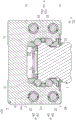
图2为图1沿剖线Ⅱ-Ⅱ的剖视示意图。FIG. 2 is a schematic cross-sectional view of FIG. 1 along line II-II.

图3为图2的区域III的放大示意图。FIG. 3 is an enlarged schematic view of region III of FIG. 2 .

图4为图1沿剖线IV-IV的剖视示意图。FIG. 4 is a schematic cross-sectional view taken along line IV-IV of FIG. 1 .

图5为图1的分解示意图。FIG. 5 is an exploded schematic view of FIG. 1 .

图6为图5的局部分解示意图。FIG. 6 is a partial exploded schematic view of FIG. 5 .

图7为图6的区域VII的放大示意图。FIG. 7 is an enlarged schematic view of the region VII of FIG. 6 .

图8为图7中的线性滑轨仅包含滑块及套管的示意图。FIG. 8 is a schematic diagram of the linear slide rail in FIG. 7 including only the slider and the sleeve.

图9为本发明实施例线性滑轨的端盖的立体示意图。FIG. 9 is a schematic perspective view of an end cover of a linear slide rail according to an embodiment of the present invention.

图10为图9的另一视角示意图。FIG. 10 is a schematic view of FIG. 9 from another perspective.

图11为本发明实施例线性滑轨的循环座的立体示意图。FIG. 11 is a schematic perspective view of a circulating seat of a linear slide rail according to an embodiment of the present invention.

图12为图11的另一视角示意图。FIG. 12 is a schematic view of FIG. 11 from another perspective.

图13为本发明实施例线性滑轨的立体剖视示意图。FIG. 13 is a schematic three-dimensional cross-sectional view of a linear slide rail according to an embodiment of the present invention.

图14为图13的区域XIV的放大示意图。FIG. 14 is an enlarged schematic view of the region XIV of FIG. 13 .

图15为图14省略滚动单元的示意图。FIG. 15 is a schematic diagram of FIG. 14 omitting the scroll unit.

具体实施方式Detailed ways

请参阅图1至图15所示,其为本发明的实施例,需先说明的是,本实施例对应附图所提及的相关数量与外形,仅用来具体地说明本发明的实施方式,以便于了解本发明的内容,而非用来局限本发明的保护范围。Please refer to FIG. 1 to FIG. 15 , which are embodiments of the present invention. It should be noted that this embodiment corresponds to the relevant quantities and shapes mentioned in the accompanying drawings, which are only used to specifically describe the embodiments of the present invention. , so as to facilitate the understanding of the content of the present invention, but not to limit the protection scope of the present invention.

如图1、图5、及图6所示,本实施例公开一种线性滑轨100,尤其是指一种标准型线性滑轨,但本发明不受限于此。其中,所述线性滑轨100包含有一导轨1、可滑动地设置于所述导轨1的一滑块2、穿设于所述滑块2内的四个套管3、装设于所述滑块2且可滑动地套设于导轨1上的两个端盖4、装设于上述滑块2内侧且位于两个端盖4之间的两个循环座5、及可滚动地设置于线性滑轨100内的四个滚动单元6。以下将分别说明本实施例线性滑轨100的各个组件具体构造,而后再适时说明线性滑轨100的各个组件间的连接关系。As shown in FIG. 1 , FIG. 5 , and FIG. 6 , the present embodiment discloses a linear slide rail 100 , especially a standard type linear slide rail, but the present invention is not limited thereto. The linear slide rail 100 includes a guide rail 1 , a slider 2 slidably disposed on the guide rail 1 , four sleeves 3 passing through the slider 2 , and installed on the slider 2 . The block 2 and the two end covers 4 slidably sleeved on the guide rail 1, the two circulating seats 5 installed on the inner side of the above-mentioned slider 2 and located between the two end covers 4, and the two end covers 5 rotatably arranged on the linear Four rolling units 6 in the slide rail 100 . The specific structure of each component of the linear slide rail 100 in this embodiment will be described below, respectively, and then the connection relationship between the various components of the linear slide rail 100 will be described in a timely manner.

如图2、图5、及图6所示,所述导轨1大致呈长条状,并且导轨1的长度方向定义为一滑动方向S,而导轨1垂直其长度方向的截面大致呈I字形。具体而言,所述导轨1顶部的相反两侧各凹设形成有平行于上述滑动方向S的两个滚动沟11。As shown in FIGS. 2 , 5 and 6 , the guide rail 1 is generally elongated, and the length direction of the guide rail 1 is defined as a sliding direction S, and the cross section of the guide rail 1 perpendicular to its length direction is generally I-shaped. Specifically, two rolling grooves 11 parallel to the above-mentioned sliding direction S are concavely formed on opposite sides of the top of the guide rail 1 .

所述滑块2大致呈长方体形,并且所述滑块2的长度小于导轨1的长度。所述滑块2凹设形成有一配合槽21。也就是说,所述滑块2垂直于其长度方向的截面大致呈倒U字形,并且所述滑块2以其配合槽21可滑动地设置于所述导轨1上。上述滑块2与导轨1的配合方式于本实施例中是以所述滚动单元6可滚动地夹持于滑块2与导轨1之间为例,但本发明不受限于此。其中,所述滑块2的长度方向平行于导轨1的长度方向(也就是,滑动方向S),并且所述配合槽21的两内侧缘与导轨1的相反两侧面之间形成有一间距(如:图2),用以容置(或夹持)上述两个循环座5。The sliding block 2 is roughly in the shape of a rectangular parallelepiped, and the length of the sliding block 2 is smaller than the length of the guide rail 1 . A matching groove 21 is formed in the slider 2 concavely. That is to say, the cross section of the sliding block 2 perpendicular to the longitudinal direction thereof is substantially inverted U-shaped, and the sliding block 2 is slidably disposed on the guide rail 1 with its matching groove 21 . The above-mentioned cooperation between the slider 2 and the guide rail 1 is taken as an example in this embodiment that the rolling unit 6 is rotatably clamped between the slider 2 and the guide rail 1 , but the present invention is not limited to this. Wherein, the length direction of the slider 2 is parallel to the length direction of the guide rail 1 (that is, the sliding direction S), and a distance is formed between the two inner edges of the matching groove 21 and the opposite sides of the guide rail 1 (such as : Figure 2), to accommodate (or clamp) the above two circulating seats 5.

更详细地说,所述配合槽21的内壁面在面向上述每个滚动沟11的部位各形成有一滚动段211,并且所述每个滚动沟11及其面向的滚动段211于垂直上述滑动方向S的截面上,皆大致呈圆弧形且具有相同的圆心,但本发明不受限于此。再者,所述滑块2于配合槽21的相反两侧部位各形成有贯穿的两个容置通道22,并且每个容置通道22平行于滑动方向S。In more detail, a rolling segment 211 is formed on the inner wall surface of the matching groove 21 facing each of the rolling grooves 11 , and each rolling groove 11 and the rolling segment 211 it faces are perpendicular to the sliding direction. On the cross section of S, all of them are generally arc-shaped and have the same center, but the present invention is not limited to this. Furthermore, the slider 2 is formed with two accommodating passages 22 on opposite sides of the matching groove 21 , and each accommodating passage 22 is parallel to the sliding direction S.

如图6至图8所示,所述每个套管3大致呈圆管状,并且上述四个套管3分别穿设于滑块2的四个容置通道22内。其中,所述每个套管3的相反两端皆局部地突伸出滑块2(如:图8),并且所述每个套管3的相反两端突伸出滑块2的部分各自凹设形成有一卡合凹槽331、及邻近于所述卡合凹槽331的一导油凹槽332,并且每个导油凹槽332连通至其套管3的内部。As shown in FIG. 6 to FIG. 8 , each of the sleeves 3 is substantially in the shape of a circular tube, and the above-mentioned four sleeves 3 are respectively inserted into the four accommodating channels 22 of the slider 2 . Wherein, the opposite ends of each sleeve 3 partially protrude out of the slider 2 (eg, FIG. 8 ), and the opposite ends of each sleeve 3 protrude from the slider 2 respectively An engaging groove 331 and an oil guiding groove 332 adjacent to the engaging groove 331 are concavely formed, and each oil guiding groove 332 communicates with the inside of the sleeve 3 thereof.

更详细地说,所述每个套管3形成有一贯穿通道31,所述每个套管3的相反两端各具有环绕于贯穿通道31的一第一阶梯部32及一第二阶梯部33。所述每个套管3的两个第一阶梯部32分别切齐于滑块2的位于相反两端的两个端面23,所述每个套管3的两个第二阶梯部33分别突伸出滑块2的上述两个端面23,并且所述每个套管3的两个第二阶梯部33各自凹设形成有一个所述卡合凹槽331及邻近于上述卡合凹槽331的一个所述导油凹槽332。In more detail, each sleeve 3 forms a through channel 31 , and opposite ends of each sleeve 3 respectively have a first stepped portion 32 and a second stepped portion 33 surrounding the through channel 31 . . The two first stepped portions 32 of each sleeve 3 are respectively aligned with the two end faces 23 located at opposite ends of the slider 2 , and the two second stepped portions 33 of each sleeve 3 protrude respectively. The two end faces 23 of the sliding block 2 come out, and the two second stepped portions 33 of each sleeve 3 are respectively recessed to form one of the engaging grooves 331 and a groove adjacent to the engaging grooves 331. One of the oil guiding grooves 332 .

在本实施例中,所述每个卡合凹槽331大致呈三角柱状,用以与下述的卡合凸块523互相卡合。再者,所述每个导油凹槽332大致呈四角柱状、且连通至其套管3的贯穿通道31。进一步地说,所述每个套管3的内壁凹设形成有平行于上述滑动方向S的两个链带容置槽34,并且所述两个链带容置槽34分别位于其套管3的两个第一阶梯部32的邻近两个第二阶梯部33的部位。也就是说,每个链带容置槽34的一端大致位于上述其中一个第一阶梯部32的邻近其对应的第二阶梯部33的部位,并且该链带容置槽34的另一端大致位于上述其中另一个第一阶梯部32的邻近其对应的第二阶梯部33的部位。需说明的是,本实施例虽然是以卡合凹槽331大致呈三角柱状、及导油凹槽332大致呈四角柱状为例,但本发明不受限于此。In this embodiment, each of the engaging grooves 331 is substantially in the shape of a triangular column for engaging with the engaging protrusions 523 described below. Furthermore, each of the oil guiding grooves 332 is substantially in the shape of a quadrangular column, and communicates with the through passage 31 of the sleeve 3 thereof. Further, the inner wall of each sleeve 3 is concavely formed with two chain belt accommodating grooves 34 parallel to the above-mentioned sliding direction S, and the two chain belt accommodating grooves 34 are respectively located in the sleeve 3 thereof. The positions of the two first stepped parts 32 adjacent to the two second stepped parts 33 . That is to say, one end of each chain belt accommodating groove 34 is approximately located at a position adjacent to the corresponding second step portion 33 of one of the first stepped portions 32 , and the other end of the chain belt accommodating groove 34 is approximately located at a position adjacent to its corresponding second stepped portion 33 . A portion of the other first stepped portion 32 is adjacent to its corresponding second stepped portion 33 . It should be noted that in this embodiment, although the engaging groove 331 is substantially in the shape of a triangular column, and the oil guiding groove 332 is substantially in the shape of a quadrangular column, the present invention is not limited thereto.

如图1、图4、图5、图9、及图10所示,所述两个端盖4分别装设于滑块2的两个端面23、且可滑动地套设于导轨1上。其中,所述端盖4为搭配于导轨1的倒U字形构造,也就是说,本实施例的端盖4内缘形状大致对应且略大于导轨1的截面形状。As shown in FIG. 1 , FIG. 4 , FIG. 5 , FIG. 9 , and FIG. 10 , the two end caps 4 are respectively installed on the two end surfaces 23 of the slider 2 , and are slidably sleeved on the guide rail 1 . The end cover 4 is an inverted U-shaped structure matched with the guide rail 1 , that is, the shape of the inner edge of the end cover 4 in this embodiment roughly corresponds to and is slightly larger than the cross-sectional shape of the guide rail 1 .

进一步地说,所述每个端盖4在其面向滑块2的部位凹设形成有四个大致呈U字形的转向槽41,并且所述每个端盖4的四个转向槽41是分别对应于如下文所述的四个循环部51。从另一个角度说,所述每个端盖4的四个转向槽41的一端(如:外侧端)是分别对应于设置于滑块2内侧的四个套管3,并且所述每个端盖4的四个转向槽41的另一端(如:内侧端)是分别对应于设置于滑块2内侧的四个滚动段211。Further, each end cover 4 has four substantially U-shaped turning grooves 41 concavely formed at the portion facing the slider 2 , and the four turning grooves 41 of each end cover 4 are respectively Corresponds to the four circulation sections 51 as described below. From another perspective, one end (eg, the outer end) of the four diverting grooves 41 of each end cover 4 corresponds to the four sleeves 3 disposed on the inner side of the slider 2, and each end The other ends (eg, inner ends) of the four turning grooves 41 of the cover 4 correspond to the four rolling segments 211 disposed on the inner side of the slider 2 respectively.

所述每个端盖4在其面向滑块2的部位进一步凸设形成有两个结合凸肋42,并且所述每个端盖4的两个结合凸肋42在位置上分别对应于如下文所述的两个循环座5的中保持部53。在所述每个端盖4中,所述每个结合凸肋42是位于相邻的两个转向槽41之间、且自相邻的两个转向槽41之间的部位延伸所形成。换句话说,在所述每个端盖4中,所述两个结合凸肋42的其中一个结合凸肋42位于四个转向槽41的其中两个相邻的转向槽41之间、且自其中两个相邻的转向槽41之间的部分延伸所形成;并且,所述两个结合凸肋42的其中另外一个结合凸肋42位于四个转向槽41的其中另外两个相邻的转向槽41之间、且自其中另外两个相邻的转向槽41之间的部分延伸所形成。更详细地说,在本实施例中,所述每个结合凸肋42包含有一第一肋条部421及相连于第一肋条部421的一第二肋条部422,所述第一肋条部421的宽度大于第二肋条部422的宽度,并且第二肋条部422的宽度朝远离第一肋条部421的方向递增,而所述第一肋条部421的厚度小于第二肋条部422的厚度。The position of each end cover 4 facing the slider 2 is further formed with two combined ribs 42 , and the positions of the two combined ribs 42 of each end cover 4 correspond to the following: The middle holding parts 53 of the two circulating seats 5 . In each of the end caps 4 , each of the combined protruding ribs 42 is located between two adjacent turning grooves 41 and extends from a position between two adjacent turning grooves 41 . In other words, in each of the end caps 4, one of the two engaging ribs 42 is located between two adjacent ones of the four steering grooves 41, and is independent from the two adjacent steering grooves 41. The part between the two adjacent turning grooves 41 is formed by extending; and the other one of the two combining ribs 42 is located in the other two adjacent turnings of the four turning grooves 41 It is formed between the grooves 41 and extending from the part between the other two adjacent diverting grooves 41 . More specifically, in this embodiment, each of the combining protruding ribs 42 includes a first rib portion 421 and a second rib portion 422 connected to the first rib portion 421 . The width is greater than the width of the second rib portion 422 , and the width of the second rib portion 422 increases in the direction away from the first rib portion 421 , and the thickness of the first rib portion 421 is smaller than that of the second rib portion 422 .

所述每个端盖4在其面向滑块2的部位进一步凹设形成有一导油路径43,所述导油路径43环绕地设置于四个转向槽41的周围、且与四个转向槽41在空间上相连通。如上所述,在每个所述端盖4中,由于导油路径43与四个转向槽41在空间上相连通、并且四个转向槽41的一端(如:外侧端)是分别对应于四个套管3,因此所述导油路径43与相邻的四个导油凹槽332在空间上也相连通。Each end cover 4 is further recessed to form an oil guide path 43 at the portion facing the slider 2 , and the oil guide path 43 is circumferentially arranged around the four turning grooves 41 and is connected with the four turning grooves 41 . connected in space. As mentioned above, in each of the end covers 4, since the oil guide path 43 is in spatial communication with the four diverting grooves 41, and one end (eg, the outer end) of the four diverting grooves 41 is corresponding to the four diverting grooves 41 respectively Therefore, the oil guiding path 43 is also in spatial communication with the four adjacent oil guiding grooves 332 .

借此,本发明实施例的线性滑轨100能通过其端盖4的导油路径43与套管3的导油凹槽332两者的结构设计与彼此之间的配合关系,以使得当润滑油(如:滚珠润滑油)注入于端盖4的导油路径43时,润滑油能进一步通过套管3的导油凹槽332进入套管3的内部,从而平衡润滑油于端盖4中的压力、并且有效地避免润滑油无法持续注入端盖4中或者端盖4因润滑油的压力过大而脱离滑块2(也即,爆油)的情况发生。Thereby, the linear slide rail 100 of the embodiment of the present invention can pass the structural design of the oil guide path 43 of the end cover 4 and the oil guide groove 332 of the sleeve 3 and the matching relationship between each other, so that when lubricating When oil (eg: ball lubricating oil) is injected into the oil guide path 43 of the end cover 4 , the lubricating oil can further enter the inside of the sleeve 3 through the oil guide groove 332 of the sleeve 3 , so as to balance the lubricating oil in the end cover 4 and effectively avoid the situation that the lubricating oil cannot be continuously injected into the end cover 4 or the end cover 4 is separated from the slider 2 (ie, oil explosion) due to the excessive pressure of the lubricating oil.

所述每个端盖4在其面向滑块2的部位进一步凸设形成有一大致围绕导油路径43的突缘44,并且所述每个端盖4的突缘44无间隙地紧抵于滑块2的相对应所述端面23。更具体地说,在每个所述端盖4中,所述导油路径43与四个转向槽41之间大致由突缘44隔开,并且导油路径43与四个转向槽41之间能通过突缘44的至少一导油开口441而在空间上相连通。Each end cover 4 further protrudes and forms a flange 44 at the portion facing the slider 2 that substantially surrounds the oil guide path 43 , and the flange 44 of each end cover 4 abuts against the slider without any gap. The end face 23 of the block 2 corresponds to said end face 23 . More specifically, in each of the end caps 4 , the oil guide path 43 and the four turning grooves 41 are substantially separated by the flange 44 , and the oil guide path 43 and the four turning grooves 41 are separated by a flange 44 . It can be spatially communicated through at least one oil guiding opening 441 of the flange 44 .

所述每个端盖4的一侧边进一步形成有一注油孔45,所述每个端盖4的导油路径43位于注油孔45及其相邻的四个导油凹槽332之间,以使得所述端盖4的注油孔45及其相邻的四个导油凹槽332经由所导油路径43而在空间上相连通。An oil injection hole 45 is further formed on one side of each end cover 4, and the oil guide path 43 of each end cover 4 is located between the oil injection hole 45 and the four adjacent oil guide grooves 332, so as to The oil filling hole 45 of the end cover 4 and its adjacent four oil guiding grooves 332 are spatially communicated via the oil guiding path 43 .

请参阅图5至图8、并请一并参阅图11及图12,所述两个循环座5大致位于上述两个端盖4之间、且分别装设于滑块2的内侧。更具体地说,所述两个循环座5分别位于滑块2的配合槽21的相反两侧。由于本实施例的两个循环座5为大致相同或对称的构造,所以下述仅介绍其中一个循环座5的构造,而后再说明循环座5与其他构件之间的连接关系。Please refer to FIG. 5 to FIG. 8 , and also refer to FIG. 11 and FIG. 12 , the two circulating seats 5 are approximately located between the two end covers 4 and are respectively installed on the inner side of the slider 2 . More specifically, the two circulating seats 5 are respectively located on opposite sides of the matching groove 21 of the slider 2 . Since the two circulating seats 5 in this embodiment have substantially the same or symmetrical structure, the following describes only the structure of one of the circulating seats 5, and then describes the connection relationship between the circulating seat 5 and other components.

所述循环座5包含有两个循环部51、两个连接部52、及一个中保持部53。其中,所述两个连接部52连接于两个循环部51之间;也就是说,所述两个连接部52的其中一个连接部52连接两个循环部51彼此相邻的一端,并且其中另一个连接部52连接于两个循环部51彼此相邻的另一端。The circulating seat 5 includes two circulating parts 51 , two connecting parts 52 , and a middle holding part 53 . Wherein, the two connection parts 52 are connected between the two circulation parts 51; that is, one of the connection parts 52 of the two connection parts 52 connects one end of the two circulation parts 51 adjacent to each other, and wherein The other connection portion 52 is connected to the other ends of the two circulation portions 51 adjacent to each other.

更详细地说,所述每个循环部51具有分别位于其两端处的两个转向轨道511、及分别位于两个转向轨道511相反侧的两个抵靠面512。其中,彼此相邻且分属不同循环部51的两个转向轨道511是以一个所述连接部52来连接、并相对于所述连接部52大致呈镜像对称设置。所述每个转向轨道511的路径大致呈半圆形,但本发明不受限于此。In more detail, each circulating portion 51 has two turning rails 511 at both ends thereof, and two abutting surfaces 512 respectively positioned on opposite sides of the two turning rails 511 . Wherein, the two diverting rails 511 adjacent to each other and belonging to different circulation parts 51 are connected by one of the connecting parts 52 , and are generally mirror-symmetrical with respect to the connecting parts 52 . The path of each turning track 511 is substantially semicircular, but the present invention is not limited thereto.

再者,所述每个连接部52大致呈三角形片状、且具有一第一端部521及一第二端部522,所述第一端部521的宽度大于第二端部522的宽度,并且所述每个连接部52于其第一端部521的两侧具有朝彼此远离方向延伸形成的两个卡合凸块523。进一步地说,所述每个连接部52形成有一圆孔524,所述每个连接部52的圆孔524位于其第一端部521、且位于两个卡合凸块523之间,并且所述每个连接部52的圆孔524能用以供一螺丝穿设,以使得所述循环座5锁固于滑块2上,但本发明不受限于此。举例来说,在本发明未绘示的其它实施例中,所述连接部52的圆孔524也可以省略或是以其他构造取代。Furthermore, each connecting portion 52 is substantially in the shape of a triangular sheet, and has a first end portion 521 and a second end portion 522 , the width of the first end portion 521 is greater than the width of the second end portion 522 , In addition, each connecting portion 52 has two engaging protrusions 523 extending away from each other on both sides of the first end portion 521 of the connecting portion 52 . Further, each connecting portion 52 is formed with a circular hole 524, and the circular hole 524 of each connecting portion 52 is located at the first end portion 521 of the connecting portion 52 and is located between the two engaging protrusions 523, and the The circular hole 524 of each connecting portion 52 can be used for a screw to pass through, so that the circulating seat 5 is locked on the slider 2 , but the invention is not limited thereto. For example, in other embodiments not shown in the present invention, the circular hole 524 of the connecting portion 52 may also be omitted or replaced with other structures.

所述中保持部53的相反两端分别连接于两个连接部52,并且所述中保持部53分别与两个连接部52形成有两个结合凹口54。更详细地说,所述中保持部53整体呈条状、且包含有一第一条状部531及相连于第一条状部531的一第二条状部532,所述第一条状部531的宽度大于第二条状部532的宽度,并且第二条状部532的宽度朝远离第一条状部531的方向递增,而所述第一条状部531的厚度小于第二条状部532的厚度。The opposite ends of the middle holding portion 53 are respectively connected to the two connecting portions 52 , and the middle holding portion 53 and the two connecting portions 52 are respectively formed with two combining notches 54 . More specifically, the middle holding portion 53 is in the shape of a strip as a whole, and includes a first strip portion 531 and a second strip portion 532 connected to the first strip portion 531 . The first strip portion 532 The width of the second strip portion 531 is greater than the width of the second strip portion 532, and the width of the second strip portion 532 increases in the direction away from the first strip portion 531, and the thickness of the first strip portion 531 is smaller than that of the second strip portion 531. thickness of the portion 532.

进一步地说,所述第二条状部532的相反两端分别局部地且一体成型地连接于两个连接部52,所述中保持部53的相反两端未与两个连接部52连接的部分各具有一第一结合面533,并且所述第一结合面533的形状大致呈T字形。Further, the opposite ends of the second strip portion 532 are respectively partially and integrally connected to the two connecting portions 52 , and the opposite ends of the middle holding portion 53 are not connected to the two connecting portions 52 . Each part has a first joint surface 533, and the shape of the first joint surface 533 is substantially T-shaped.

需说明的是,本实施例虽然是以所述第二条状部532的相反两端分别局部地且一体成型地连接于两个连接部52为例,但本发明不受限于此。举例来说,所述第二条状部532的相反两端也可以例如是可分离地设置于两个连接部52。It should be noted that in this embodiment, although the opposite ends of the second strip portion 532 are respectively locally and integrally connected to the two connecting portions 52 as an example, the present invention is not limited thereto. For example, opposite ends of the second strip portion 532 may also be detachably disposed on the two connecting portions 52 .

此外,配合于所述第一结合面533,所述每个连接部52进一步形成有相连且大致垂直于相对应的第一结合面533的一第一嵌合面525,并且所述第一嵌合面525与相对应的第一结合面533包围地形成有一个所述结合凹口54。In addition, in cooperation with the first joint surface 533, each connecting portion 52 is further formed with a first joint surface 525 which is connected to and substantially perpendicular to the corresponding first joint surface 533, and the first joint surface 525 is formed. The engaging surface 525 and the corresponding first engaging surface 533 are surrounded by one of the engaging recesses 54 .

以上为本实施例循环座5的构造介绍,下述接着说明循环座5与其他构件之间的连接关系。所述每个循环座5固定于滑块2,并且所述每个循环座5的两个循环部51分别与相邻的两个套管3相接、以与所述滑块2、所述导轨1、及所述两个端盖4共同界定出两个循环通道C(如:图13),并且所述两个循环通道C与两个导油路径43在空间上皆相连通。进一步地说,所述每个循环部51的两个转向轨道511分别与相对应的套管3及滚动段211相接,以使得所述每个循环部51的两个转向轨道511及其相对应的套管3、滑块2的滚动段211、导轨1的滚动沟11、及两个端盖4的相对应的转向槽41共同构成一个循环通道C(如:图13)。The structure of the circulation seat 5 of the present embodiment has been introduced above, and the following describes the connection relationship between the circulation seat 5 and other components. Each circulating seat 5 is fixed to the sliding block 2, and the two circulating parts 51 of each circulating seat 5 are respectively connected with the two adjacent sleeves 3 to connect with the sliding block 2, the The guide rail 1 and the two end caps 4 jointly define two circulation channels C (eg, FIG. 13 ), and the two circulation channels C and the two oil guide paths 43 are spatially connected. Further, the two turning tracks 511 of each circulating portion 51 are respectively connected with the corresponding sleeve 3 and the rolling segment 211, so that the two turning tracks 511 of each circulating portion 51 and their relative The corresponding sleeve 3 , the rolling segment 211 of the slider 2 , the rolling groove 11 of the guide rail 1 , and the corresponding turning grooves 41 of the two end covers 4 together form a circulation channel C (eg, FIG. 13 ).

再者,所述每个循环座5的两个连接部52分别夹持于上述两个端盖4与滑块2之间。也就是说,所述每个循环座5的两个连接部52的其中一个连接部52夹持于上述两个端盖4的其中一个端盖4与滑块2之间,并且所述每个循环座5的两个连接部52的其中另一个连接部52夹持于上述两个端盖4的其中另一个端盖4与滑块2之间。Furthermore, the two connecting parts 52 of each circulating seat 5 are respectively clamped between the two end caps 4 and the slider 2 . That is to say, one of the two connecting parts 52 of the two connecting parts 52 of each circulating seat 5 is clamped between one of the above-mentioned two end covers 4 and the slider 2, and each of the two connecting parts 52 The other one of the two connecting parts 52 of the circulating seat 5 is clamped between the other one of the two end caps 4 and the slider 2 .

如图5、图9、图10、及图15,所述每个端盖4的两个结合凸肋42在位置上分别对应于两个循环座5的中保持部53,所述每个端盖4的两个结合凸肋42于几何上互补于其面向(其相邻)的两个结合凹口54,并且所述每个端盖4的两个结合凸肋42与其面向的两个结合凹口54大致无间隙地结合。5 , 9 , 10 , and 15 , the two engaging ribs 42 of each end cover 4 correspond in position to the middle holding portions 53 of the two circulating seats 5 respectively. The two engaging ribs 42 of the cover 4 are geometrically complementary to the two engaging notches 54 it faces (which are adjacent to it), and the two engaging ribs 42 of each end cover 4 engage with the two engaging ribs 42 it faces. The notches 54 are engaged substantially without gaps.

借此,本发明实施例的线性滑轨100能通过其端盖4的结合凸肋42与循环座5的结合凹口54两者的结构设计与彼此之间的配合关系,以使得端盖4与循环座5之间结合部分的间隙或高低断差能被有效地消除(也即,端盖4与循环座5之间结合部分的跳点能被有效地消除),进而使得滚动单元6于线性滑轨100中能够滚动地更佳顺畅。Thereby, the linear slide rail 100 of the embodiment of the present invention can make the end cover 4 through the structural design and the matching relationship between the combination convex rib 42 of the end cover 4 and the combination recess 54 of the circulation seat 5 and each other. The gap or height difference between the joint part and the circulating seat 5 can be effectively eliminated (that is, the jump point of the joint part between the end cover 4 and the circulating seat 5 can be effectively eliminated), so that the rolling unit 6 can be The linear slide rail 100 can roll more smoothly.

更具体地说,配合于所述每个中保持部53的第一结合面533,所述每个结合凸肋42的面向相对应的中保持部53的部分具有一第二结合面423,所述每个第二结合面423的形状相同于第一结合面533的形状、也大致呈T字形,并且所述每个结合凸肋42的第二结合面423无间隙地结合于相对应的中保持部53的第一结合面533。More specifically, matching with the first joint surface 533 of each middle holding part 53 , the part of each joint convex rib 42 facing the corresponding middle holding part 53 has a second joint surface 423 , so The shape of each second joint surface 423 is the same as the shape of the first joint surface 533, and is also substantially T-shaped, and the second joint surface 423 of each joint convex rib 42 is combined with the corresponding middle The first joint surface 533 of the holding portion 53 .

再者,在所述每个端盖4中,所述每个结合凸肋42具有相连且大致垂直于其第二结合面423的一第二嵌合面424,并且所述第二嵌合面424为第二肋条部422的相反于第一肋条部421的一侧表面。其中,当所述每个结合凸肋42的第二结合面423结合于相对应的中保持部53的第一结合面533时,所述每个结合凸肋42的第二嵌合面424结合于相对应的连接部52的第一嵌合面525,以使得所述每个结合凸肋42嵌合于相对应的循环座5。Furthermore, in each of the end caps 4, each of the engaging ribs 42 has a second engaging surface 424 that is connected to and substantially perpendicular to the second engaging surface 423 thereof, and the second engaging surface is 424 is a side surface of the second rib part 422 opposite to the first rib part 421 . Wherein, when the second coupling surface 423 of each coupling protruding rib 42 is coupled with the corresponding first coupling surface 533 of the middle holding portion 53 , the second fitting surface 424 of each coupling protruding rib 42 is coupled to the first fitting surface 525 of the corresponding connecting portion 52 , so that each of the combining ribs 42 is fitted to the corresponding circulating seat 5 .

请继续参阅图15,从另一个角度说,当所述每个结合凸肋42结合于相对应的结合凹口54时,所述第一肋条部421的面向相对应的循环通道C的表面大致切齐于第一条状部531的面向相对应的循环通道C的表面、且与第一条状部531的表面实质上不具有任何的高低断差(也即,不具有任何的高低起伏),并且所述第二肋条部422的面向相对应的循环通道C的表面大致切齐于第二条状部532的面向相对应的循环通道C的表面、且与所述第二条状部532的表面实质上不具有任何的高低断差。Please continue to refer to FIG. 15 , from another perspective, when each of the coupling protruding ribs 42 is coupled to the corresponding coupling recess 54 , the surface of the first rib portion 421 facing the corresponding circulation channel C is approximately It is aligned with the surface of the first strip portion 531 that faces the corresponding circulation channel C, and does not substantially have any height difference with the surface of the first strip portion 531 (that is, does not have any undulations). , and the surface of the second rib portion 422 facing the corresponding circulation channel C is substantially aligned with the surface of the second strip portion 532 facing the corresponding circulation channel C, and the second strip portion 532 The surface does not substantially have any height difference.

如图7所示,所述每个连接部52的两个卡合凸块523分别与相邻的两个第二阶梯部33的卡合凹槽331互相卡合,以使得所述每个连接部52被夹持于相邻的两个套管3之间。再者,所述每个循环部51的两个抵靠面512分别抵靠于滑块2的两个端面23、且也分别抵靠于相邻的两个套管3的第一阶梯部32。As shown in FIG. 7 , the two engaging protrusions 523 of each connecting portion 52 are respectively engaged with the engaging grooves 331 of the two adjacent second step portions 33 , so that each connecting portion 52 is engaged with each other. The portion 52 is sandwiched between two adjacent sleeves 3 . Furthermore, the two abutting surfaces 512 of each circulating portion 51 respectively abut against the two end surfaces 23 of the slider 2 , and also respectively abut against the first stepped portions 32 of the two adjacent sleeves 3 . .

借此,本发明实施例的线性滑轨100能通过其循环座5的连接部52与套管3的端部两者的结构设计与彼此之间的配合关系,以使得套管3能在不需要太多固定组件(如:螺丝)的情况下被巧妙地固定于滑块2上,进而有效地提升装置整体的紧配程度、提升装置的组装便利性、并且减少装置的制造成本。Thereby, the linear slide rail 100 of the embodiment of the present invention can use the structural design of the connecting portion 52 of the circulation seat 5 and the end portion of the sleeve 3 and the matching relationship between each other, so that the sleeve 3 can be When too many fixing components (such as screws) are required, they are cleverly fixed on the slider 2, thereby effectively improving the overall tightness of the device, improving the assembly convenience of the device, and reducing the manufacturing cost of the device.

值得一提的是,在本实施例中,所述每个连接部52的厚度相同于相邻的两个第二阶梯部33突伸出滑块2的相对应的端面23的高度。借此,当所述每个端盖4装设于滑块2的相对应的端面23时,所述每个端盖4在与上述连接部52及第二阶梯部33接触的部分,仅需要平面的结构设计、不需要复杂的结构设计,即能与滑块2平稳地结合。It is worth mentioning that, in this embodiment, the thickness of each connecting portion 52 is the same as the height at which two adjacent second stepped portions 33 protrude from the corresponding end surface 23 of the slider 2 . Therefore, when each end cap 4 is mounted on the corresponding end face 23 of the slider 2 , the portion of each end cap 4 in contact with the connecting portion 52 and the second stepped portion 33 only needs to be The plane structure design does not require complicated structure design, that is, it can be smoothly combined with the slider 2 .

进一步地说,在所述每个循环座5中,所述中保持部53隔开相邻的两个循环通道C,并且所述第一条状部531面向导轨1,而所述第二条状部532面向滑块2。所述中保持部53的第一条状部531及第二条状部532与滑块2的配合槽21的内壁面共同包围地形成有两个链带导引槽55,并且所述两个链带导引槽55分别位于相邻的两个循环通道C的循环路径上。Further, in each circulating seat 5, the middle holding part 53 separates two adjacent circulating channels C, and the first strip-shaped part 531 faces the guide rail 1, while the second strip-shaped part 531 faces the guide rail 1. The shaped portion 532 faces the slider 2 . The first strip portion 531 and the second strip portion 532 of the middle holding portion 53 and the inner wall surface of the matching groove 21 of the slider 2 are formed with two belt guide grooves 55 , and the two belt guide grooves 55 are formed together. The chain guide grooves 55 are located on the circulation paths of the two adjacent circulation channels C, respectively.

如图2、图3、图5、及图6所示,所述四个滚动单元6分别可滚动地容置于上述四个循环通道C内。其中,上述每个滚动单元6于本实施例中包含有一链带61及设置于上述链带61的多个滚珠62,但本发明不受限于此。举例来说,在本发明未绘示的其它实施例中,所述滚动单元6可以是仅包含有多个滚珠62、或者所述滚动单元6也可以是包含有一链带61及设置于上述链带61的多个滚柱。As shown in FIG. 2 , FIG. 3 , FIG. 5 , and FIG. 6 , the four rolling units 6 are respectively rotatably accommodated in the above-mentioned four circulation channels C. Wherein, each of the above-mentioned rolling units 6 includes a chain belt 61 and a plurality of balls 62 disposed on the chain belt 61 in this embodiment, but the present invention is not limited thereto. For example, in other embodiments not shown in the present invention, the rolling unit 6 may only include a plurality of balls 62 , or the rolling unit 6 may also include a chain belt 61 arranged on the chain Multiple rollers with 61.

进一步地说,在本实施例中,在所述每个滚动单元6及相对应的循环通道C中,所述滚动单元6的链带61是设置于链带导引槽55中,并且所述滚动单元6的链带61与滑块2的配合槽21的内壁面保持一段距离(如:图3)。其中,在所述滚动单元6滚动的过程中,所述链带61与中保持部53的第一条状部531接触、且不与所述滑块2接触,但本发明不受限于此。Further, in this embodiment, in each rolling unit 6 and the corresponding circulation channel C, the chain belt 61 of the rolling unit 6 is arranged in the chain belt guide groove 55, and the The chain belt 61 of the rolling unit 6 keeps a certain distance from the inner wall surface of the matching groove 21 of the slider 2 (eg, FIG. 3 ). Wherein, during the rolling process of the rolling unit 6 , the chain belt 61 is in contact with the first strip portion 531 of the middle holding portion 53 and not in contact with the slider 2 , but the present invention is not limited to this .

借此,本发明实施例的线性滑轨100能通过其滚动单元6的链带61与链带导引槽55两者的结构设计与彼此之间的配合关系(也即,链带导引槽55单边开放的结构设计),使得滚动单元6的链带61于链带导引槽55中能够移动地更佳顺畅,并且可以有效地减少链带卡炼的情况发生。Thereby, the linear slide rail 100 of the embodiment of the present invention can pass the structural design of the chain belt 61 of the rolling unit 6 and the chain belt guide groove 55 and the matching relationship between each other (that is, the chain belt guide groove 55). 55 unilaterally open structure design), so that the chain belt 61 of the rolling unit 6 can move more smoothly in the chain belt guide groove 55, and can effectively reduce the occurrence of chain belt jamming.

需额外说明的是,为了提升本实施例循环座5与相对应端盖4之间的定位效果,每个循环部51的两端可以分别朝彼此远离的方向延伸形成有两个定位柱513(如:图11),并且上述每个定位柱513嵌设于相对应的端盖4内,但本发明不受限于此。It should be noted that, in order to improve the positioning effect between the circulation seat 5 and the corresponding end cover 4 in this embodiment, two positioning posts 513 ( Such as: FIG. 11 ), and each of the above-mentioned positioning posts 513 is embedded in the corresponding end cap 4 , but the present invention is not limited thereto.

此外,如图2及图5,为了提升本实施例线性滑轨100的防尘效果,所述线性滑轨100进一步包含有设置于滑块2配合槽21中的一防尘模块7。所述防尘模块7包含有一个上防尘件71及两个下防尘件72,其中,所述上防尘件71设置于两个循环座5的上侧,并且所述两个下防尘件72分别设置于两个循环座5的下侧,但本发明不受限于此。In addition, as shown in FIGS. 2 and 5 , in order to improve the dustproof effect of the linear slide rail 100 of the present embodiment, the linear slide rail 100 further includes a dustproof module 7 disposed in the matching groove 21 of the slider 2 . The dust-proof module 7 includes an upper dust-proof member 71 and two lower dust-proof members 72, wherein the upper dust-proof member 71 is arranged on the upper side of the two circulating seats 5, and the two lower dust-proof members 71. The dust pieces 72 are respectively disposed on the lower sides of the two circulation seats 5, but the present invention is not limited thereto.

此外,本实施例中的导轨1、滑块2、套管3、端盖4、及滚动单元6优选是不可挠的构造且由硬质材料(如:金属)所制成,而所述循环座5优选是可挠的构造且由软质材料(如:橡胶)所制成,但本发明不受限于此。In addition, the guide rail 1 , the slider 2 , the sleeve 3 , the end cover 4 , and the rolling unit 6 in this embodiment are preferably inflexible structures and made of hard materials (eg, metal), and the circulating The seat 5 is preferably of flexible construction and made of a soft material (eg, rubber), but the invention is not limited thereto.

需说明的是,本实施例的线性滑轨100虽然是以上述多个构件彼此搭配做说明,但于本发明未绘示的其他实施例中,上述多个构件的其中部分的构件也可以组装成一模块,并且单独地应用(如:贩卖)或是搭配其他构件使用,并不局限于本实施例所载。举例来说,上述多个构件中的滑块2、套管3、及循环座5能够组装成线性滑轨100的一固定模块,并且上述多个构件中的滑块2、套管3、及端盖4能够组装成线性滑轨100的一导油路径模块。It should be noted that although the linear slide rail 100 in this embodiment is described by the above-mentioned multiple components being matched with each other, in other embodiments not shown in the present invention, some of the above-mentioned multiple components can also be assembled It can be used as a module and used alone (eg, sold) or used in conjunction with other components, and is not limited to what is described in this embodiment. For example, the slider 2 , the sleeve 3 , and the circulating seat 5 in the above-mentioned multiple components can be assembled into a fixed module of the linear slide rail 100 , and the slider 2 , the sleeve 3 , and The end cover 4 can be assembled into an oil guide path module of the linear slide rail 100 .

[本发明实施例的技术功效][Technical Effects of the Embodiments of the Invention]

综上所述,本发明实施例公开的线性滑轨100能通过其端盖4的导油路径43与套管3的导油凹槽332两者的结构设计与彼此之间的配合关系,以使得当润滑油(如:滚珠润滑油)注入于端盖4的导油路径43时,润滑油能进一步通过套管3的导油凹槽332进入套管3的内部,从而平衡润滑油于端盖4中的压力、并且有效地避免润滑油无法持续注入端盖4中或者端盖4因润滑油的压力过大而脱离滑块2(也即,爆油)的情况发生。To sum up, the linear slide rail 100 disclosed in the embodiment of the present invention can achieve the matching relationship between the structural design of the oil guide path 43 of the end cover 4 and the oil guide groove 332 of the casing 3 and the cooperation relationship with each other. So that when lubricating oil (eg: ball lubricating oil) is injected into the oil guiding path 43 of the end cover 4, the lubricating oil can further enter the inside of the casing 3 through the oil guiding groove 332 of the casing 3, so as to balance the lubricating oil at the end The pressure in the cover 4 can effectively avoid the situation that the lubricating oil cannot be continuously injected into the end cover 4 or the end cover 4 is separated from the slider 2 due to the excessive pressure of the lubricating oil (ie, oil explosion).

再者,本发明实施例公开的线性滑轨100能通过其端盖4的结合凸肋42与循环座5的结合凹口54两者的结构设计与彼此之间的配合关系,以使得端盖4与循环座5之间结合部分的间隙或高低断差能被有效地消除(也即,端盖4与循环座5之间结合部分的跳点能被有效地消除),进而使得滚动单元6于线性滑轨100中能够滚动地更佳顺畅。Furthermore, the linear slide rail 100 disclosed in the embodiment of the present invention can use the structural design of the combination rib 42 of the end cover 4 and the combination recess 54 of the circulation seat 5 and the matching relationship between each other, so that the end cover can be The gap or height difference between the joint part 4 and the circulating seat 5 can be effectively eliminated (that is, the jumping point of the joint part between the end cover 4 and the circulating seat 5 can be effectively eliminated), thereby making the rolling unit 6 The linear slide rail 100 can roll more smoothly.

此外,本发明实施例公开的线性滑轨100能通过其循环座5的连接部52与套管3的端部两者的结构设计与彼此之间的配合关系,以使得套管3能在不需要太多固定组件(如:螺丝)的情况下被巧妙地固定于滑块2上,进而有效地提升装置整体的紧配程度、提升装置的组装便利性、并且减少装置的制造成本。In addition, the linear slide rail 100 disclosed in the embodiment of the present invention can use the structural design of the connecting portion 52 of the circulation seat 5 and the end portion of the sleeve 3 and the matching relationship between each other, so that the sleeve 3 can be When too many fixing components (such as screws) are required, they are cleverly fixed on the slider 2, thereby effectively improving the overall tightness of the device, improving the assembly convenience of the device, and reducing the manufacturing cost of the device.

以上所述仅为本发明的优选可行实施例,并非用来局限本发明的保护范围,凡依本发明权利要求书所做的均等变化与修饰,皆应属本发明的权利要求书的保护范围。The above descriptions are only preferred and feasible embodiments of the present invention, and are not intended to limit the protection scope of the present invention. All equivalent changes and modifications made according to the claims of the present invention shall fall within the protection scope of the claims of the present invention. .

Claims (10)

1.一种线性滑轨,其特征在于,所述线性滑轨包括:1. A linear slide rail, characterized in that, the linear slide rail comprises: 一导轨;a guide rail; 一滑块,凹设形成有一配合槽,并且所述滑块通过所述配合槽能滑动地设置于所述导轨上;其中,所述滑块于所述配合槽的相反两侧部位处各形成有贯穿的两个容置通道;A sliding block is recessed with a matching groove, and the sliding block is slidably disposed on the guide rail through the matching groove; wherein, the sliding block is formed at the opposite sides of the matching groove. There are two accommodating channels running through; 四个套管,分别穿设于所述滑块的四个所述容置通道内;four sleeves, respectively passing through the four accommodating channels of the slider; 两个端盖,分别装设于所述滑块的位于相反两端的两个端面且能滑动地套设于所述导轨上;其中,每个所述端盖在其面向所述滑块的部分处凸设形成有两个结合凸肋;Two end caps are respectively installed on the two end faces of the slider at opposite ends and slidably sleeved on the guide rail; wherein, each of the end caps faces the slider at the part thereof Two combined protruding ribs are formed protrudingly at the place; 两个循环座,位于两个所述端盖之间且分别装设于所述滑块,并且两个所述循环座分别位于所述配合槽的相反两侧;其中,每个所述循环座包含:Two circulating seats are located between the two end caps and are respectively installed on the sliders, and the two circulating seats are respectively located on opposite sides of the matching groove; wherein, each circulating seat Include: 两个循环部,分别与相邻的两个所述套管相接,以与所述滑块、所述导轨以及两个所述端盖共同界定出两个循环通道;two circulation parts, respectively connected with the two adjacent sleeves, so as to define two circulation passages together with the sliding block, the guide rail and the two end caps; 两个连接部,连接两个所述循环部,并且两个所述连接部分别夹持于两个所述端盖与所述滑块之间;及two connecting parts, connecting the two circulating parts, and the two connecting parts are respectively clamped between the two end caps and the sliding block; and 一个中保持部,所述中保持部的相反两端分别连接于两个所述连接部,且隔开相邻的两个所述循环通道;其中,所述中保持部分别与两个所述连接部形成有两个结合凹口;以及a middle holding part, the opposite ends of the middle holding part are respectively connected to the two connecting parts, and separate the two adjacent circulation channels; wherein, the middle holding part is respectively connected to the two the connecting portion is formed with two coupling notches; and 四个滚动单元,分别能滚动地设置于四个所述循环通道内;four rolling units, respectively rotatably arranged in the four said circulation channels; 其中,每个所述端盖的两个所述结合凸肋在位置上分别对应于两个所述循环座的所述中保持部,每个所述端盖的两个所述结合凸肋在几何上与其面向的两个所述结合凹口互补,并且每个所述端盖的两个所述结合凸肋与其面向的两个所述结合凹口无间隙地结合。Wherein, the two combining protruding ribs of each of the end caps correspond in position to the middle holding parts of the two circulating seats, respectively, and the two combining protruding ribs of each of the end caps are in It is geometrically complementary to the two coupling recesses it faces, and the two coupling protruding ribs of each of the end caps are combined with the two coupling recesses it faces without gaps. 2.根据权利要求1所述的线性滑轨,其特征在于,每个所述端盖在其面向所述滑块的部位处凹设形成有四个转向槽,每个所述端盖的四个所述转向槽的位置分别对应于四个所述循环部;其中,在每个所述端盖中,每个所述结合凸肋位于相邻的两个所述转向槽之间且自相邻的两个所述转向槽之间的部位延伸所形成。2 . The linear slide rail according to claim 1 , wherein each of the end caps is formed with four diverting grooves concavely at the portion facing the slider, and four turning grooves of each end cap are formed. 3 . The positions of each of the diverting grooves correspond to the four circulating parts respectively; wherein, in each of the end caps, each of the combining protruding ribs is located between two adjacent diverting grooves and is mutually opposite to each other. It is formed by extending the part between two adjacent turning grooves. 3.根据权利要求1所述的线性滑轨,其特征在于,在每个所述循环座中,所述中保持部呈条状且包含有一第一条状部及与所述第一条状部相连的一第二条状部,所述第一条状部的宽度大于所述第二条状部的宽度,所述第一条状部面向所述导轨,所述第二条状部面向所述滑块,并且所述第二条状部的相反两端分别局部地且一体成型地连接于两个所述连接部。3 . The linear slide rail according to claim 1 , wherein, in each of the recirculating seats, the middle holding portion is strip-shaped and includes a first strip-shaped portion and the first strip-shaped portion. 4 . a second strip-shaped part connected to each other, the width of the first strip-shaped part is greater than the width of the second strip-shaped part, the first strip-shaped part faces the guide rail, and the second strip-shaped part faces the guide rail The slider, and the opposite ends of the second strip portion are respectively locally and integrally connected to the two connecting portions. 4.根据权利要求3所述的线性滑轨,其特征在于,在每个所述循环座中,所述中保持部的相反两端的未与两个所述连接部连接的部分各具有一第一结合面,并且所述第一结合面的形状呈T字形;其中,每个所述结合凸肋的面向相对应的所述中保持部的部分具有一第二结合面,每个所述第二结合面的形状与所述第一结合面的形状相同,也呈T字形,并且每个所述结合凸肋的所述第二结合面无间隙地结合于相对应的所述中保持部的所述第一结合面。4 . The linear slide rail according to claim 3 , wherein, in each of the recirculating seats, the parts of the opposite ends of the middle holding part that are not connected with the two connecting parts each have a first a joint surface, and the shape of the first joint surface is T-shaped; wherein, the part of each joint convex rib facing the corresponding middle holding part has a second joint surface, each of the first joint surface The shape of the second joint surface is the same as the shape of the first joint surface, which is also T-shaped, and the second joint surface of each joint convex rib is combined with the corresponding middle holding part without gap. the first bonding surface. 5.根据权利要求3所述的线性滑轨,其特征在于,在每个所述循环座中,所述中保持部的所述第一条状部及所述第二条状部与所述滑块共同包围地形成有两个链带导引槽,并且两个所述链带导引槽分别位于相邻的两个所述循环通道的循环路径上;其中,每个所述滚动单元包含有一链带及设置于所述链带中的多个滚珠,并且在每个所述滚动单元及相对应的所述循环通道中,所述滚动单元的所述链带设置于所述链带导引槽中。5 . The linear slide rail according to claim 3 , wherein in each of the recirculating seats, the first strip portion and the second strip portion of the middle holding portion are the same as the The slider is formed with two chain belt guide grooves in a common surrounding area, and the two chain belt guide grooves are respectively located on the circulation paths of the two adjacent circulation channels; wherein, each of the rolling units includes There is a chain belt and a plurality of balls arranged in the chain belt, and in each of the rolling units and the corresponding circulation channel, the chain belt of the rolling unit is arranged on the chain belt guide into the slot. 6.根据权利要求5所述的线性滑轨,其特征在于,在每个所述滚动单元及相对应的所述循环通道中,所述滚动单元的所述链带与所述滑块的所述配合槽的内壁面保持一段距离。6 . The linear slide rail according to claim 5 , wherein in each of the rolling units and the corresponding circulation channel, the chain belt of the rolling unit and all the sliding blocks The inner wall surface of the matching groove is kept at a certain distance. 7.根据权利要求3所述的线性滑轨,其特征在于,每个所述结合凸肋包含有一第一肋条部及与所述第一肋条部相连的一第二肋条部,并且所述第一肋条部的宽度大于所述第二肋条部的宽度;其中,当每个所述结合凸肋结合于相对应的所述结合凹口时,所述第一肋条部的面向相对应的所述循环通道的表面切齐于所述第一条状部的面向相对应的所述循环通道的表面,并且所述第二肋条部的面向相对应的所述循环通道的表面切齐于所述第二条状部的面向相对应的所述循环通道的表面。7 . The linear slide rail according to claim 3 , wherein each of the combining protruding ribs comprises a first rib portion and a second rib portion connected with the first rib portion, and the first rib portion is 7 . The width of a rib portion is greater than the width of the second rib portion; wherein, when each of the combining protruding ribs is combined with the corresponding combining recess, the first rib portion faces the corresponding The surface of the circulation channel is aligned with the surface of the first strip portion facing the corresponding circulation channel, and the surface of the second rib portion facing the corresponding circulation channel is aligned with the surface of the first strip portion. The surfaces of the two strip-shaped portions face the corresponding circulation channels. 8.根据权利要求4所述的线性滑轨,其特征在于,在每个所述循环座中,每个所述连接部具有与相对应的所述第一结合面相连且垂直的一第一嵌合面,并且所述第一嵌合面与相对应的所述第一结合面包围有一个所述结合凹口;其中,在每个所述端盖中,每个所述结合凸肋具有与其第二结合面相连且垂直的一第二嵌合面;其中,当每个所述结合凸肋的所述第二结合面结合于相对应的所述中保持部的所述第一结合面时,每个所述结合凸肋的所述第二嵌合面结合于相对应的所述连接部的所述第一嵌合面。8 . The linear slide rail according to claim 4 , wherein, in each of the recirculating seats, each of the connecting portions has a first connecting surface that is connected to the corresponding first connecting surface and is vertical. 9 . a fitting surface, and the first fitting surface and the corresponding first combining surface surround one of the combining recesses; wherein, in each of the end caps, each of the combining protruding ribs has a second mating surface connected to and perpendicular to its second joint surface; wherein, when the second joint surface of each joint convex rib is combined with the corresponding first joint surface of the middle holding part At the time, the second fitting surface of each of the combining protruding ribs is combined with the first fitting surface of the corresponding connecting portion. 9.根据权利要求1所述的线性滑轨,其特征在于,每个所述套管的相反两端皆局部地突伸出所述滑块,并且每个所述套管的相反两端突伸出所述滑块的部分各自凹设形成有一卡合凹槽;其中,每个所述连接部具有朝彼此远离方向延伸形成的两个卡合凸块,并且每个所述连接部的两个所述卡合凸块分别与相邻的两个所述卡合凹槽互相卡合,以使得每个所述连接部被夹持于相邻的两个所述套管之间。9 . The linear slide rail of claim 1 , wherein opposite ends of each of the sleeves partially protrude out of the slider, and opposite ends of each of the sleeves protrude from the slider. 10 . Each of the parts protruding from the slider is concavely formed with an engaging groove; wherein, each of the connecting parts has two engaging protrusions extending away from each other, and two of the connecting parts are formed. Each of the engaging protrusions is respectively engaged with two adjacent engaging grooves, so that each connecting portion is clamped between two adjacent sleeves. 10.根据权利要求1所述的线性滑轨,其特征在于,每个所述套管的相反两端皆局部地突伸出所述滑块,每个所述套管的相反两端突伸出所述滑块的部分各自凹设形成有一导油凹槽,并且每个所述导油凹槽连通至其套管的内部;其中,每个所述端盖在其面向所述滑块的部位凹设形成有一导油路径,并且每个所述端盖的所述导油路径与相邻的四个所述导油凹槽在空间上相连通。10 . The linear slide rail of claim 1 , wherein opposite ends of each of the sleeves partially protrude out of the slider, and opposite ends of each of the sleeves protrude. 11 . An oil guiding groove is concavely formed on the part exiting the sliding block, and each of the oil guiding grooves is communicated with the inside of the sleeve; An oil guiding path is formed in the concave part, and the oil guiding path of each end cover is in spatial communication with the adjacent four oil guiding grooves.
CN201811493377.XA 2018-11-28 2018-12-07 Linear sliding rail Active CN111237335B (en)

Applications Claiming Priority (2)

Application Number Priority Date Filing Date Title
TW107142499 2018-11-28
TW107142499A TWI674167B (en) 2018-11-28 2018-11-28 Linear guideway

Publications (2)

Publication Number Publication Date
CN111237335A true CN111237335A (en) 2020-06-05
CN111237335B CN111237335B (en) 2022-03-22

Family

ID=69023656

Family Applications (1)

Application Number Title Priority Date Filing Date
CN201811493377.XA Active CN111237335B (en) 2018-11-28 2018-12-07 Linear sliding rail

Country Status (2)

Country Link
CN (1) CN111237335B (en)
TW (1) TWI674167B (en)

Cited By (2)

* Cited by examiner, † Cited by third party
Publication number Priority date Publication date Assignee Title
CN116608209A (en) * 2022-02-09 2023-08-18 银泰科技股份有限公司 Linear slide rail and its sliding block assembly structure
CN116928224A (en) * 2022-04-11 2023-10-24 鑫鑫直线精密机械(苏州)有限公司 Rolling module and chain belt of linear moving device

Citations (11)

* Cited by examiner, † Cited by third party
Publication number Priority date Publication date Assignee Title
US20010048775A1 (en) * 1997-06-16 2001-12-06 Thk Co., Ltd. Linear motion guiding apparatus
CN201047397Y (en) * 2007-06-05 2008-04-16 精浚科技股份有限公司 Rotary circulation guide structure of linear slide rail
JP2013050206A (en) * 2011-08-03 2013-03-14 Thk Co Ltd Rolling guide device
TWM497722U (en) * 2014-12-22 2015-03-21 Ome Technology Co Ltd Linear guideway and passageway module thereof
CN204716757U (en) * 2015-05-29 2015-10-21 屠能哲 Linear motion device
TW201540972A (en) * 2013-12-05 2015-11-01 Thk Co Ltd Rolling guidance device
CN105121874A (en) * 2013-05-01 2015-12-02 Thk株式会社 Rolling guide device
TWM568307U (en) * 2018-05-11 2018-10-11 精浚科技股份有限公司 Linear slide and its holding module
CN209444714U (en) * 2018-11-28 2019-09-27 精浚科技股份有限公司 Linear sliding rail
CN209444713U (en) * 2018-11-28 2019-09-27 精浚科技股份有限公司 Linear slide rail and its oil guide path module
CN209458293U (en) * 2018-11-28 2019-10-01 精浚科技股份有限公司 Linear sliding rail and fixing module thereof

Family Cites Families (3)

* Cited by examiner, † Cited by third party
Publication number Priority date Publication date Assignee Title
CN201047398Y (en) * 2007-06-05 2008-04-16 精浚科技股份有限公司 Guide assembly reinforcing structure of linear slide rail device
TWM469978U (en) * 2013-06-21 2014-01-11 Ome Technology Co Ltd Linear guideway and end cap module thereof
TWM489931U (en) * 2014-05-23 2014-11-11 Ome Technology Co Ltd Linear slide and end cover module thereof

Patent Citations (11)

* Cited by examiner, † Cited by third party
Publication number Priority date Publication date Assignee Title
US20010048775A1 (en) * 1997-06-16 2001-12-06 Thk Co., Ltd. Linear motion guiding apparatus
CN201047397Y (en) * 2007-06-05 2008-04-16 精浚科技股份有限公司 Rotary circulation guide structure of linear slide rail
JP2013050206A (en) * 2011-08-03 2013-03-14 Thk Co Ltd Rolling guide device
CN105121874A (en) * 2013-05-01 2015-12-02 Thk株式会社 Rolling guide device
TW201540972A (en) * 2013-12-05 2015-11-01 Thk Co Ltd Rolling guidance device
TWM497722U (en) * 2014-12-22 2015-03-21 Ome Technology Co Ltd Linear guideway and passageway module thereof
CN204716757U (en) * 2015-05-29 2015-10-21 屠能哲 Linear motion device
TWM568307U (en) * 2018-05-11 2018-10-11 精浚科技股份有限公司 Linear slide and its holding module
CN209444714U (en) * 2018-11-28 2019-09-27 精浚科技股份有限公司 Linear sliding rail
CN209444713U (en) * 2018-11-28 2019-09-27 精浚科技股份有限公司 Linear slide rail and its oil guide path module
CN209458293U (en) * 2018-11-28 2019-10-01 精浚科技股份有限公司 Linear sliding rail and fixing module thereof

Cited By (2)

* Cited by examiner, † Cited by third party
Publication number Priority date Publication date Assignee Title
CN116608209A (en) * 2022-02-09 2023-08-18 银泰科技股份有限公司 Linear slide rail and its sliding block assembly structure
CN116928224A (en) * 2022-04-11 2023-10-24 鑫鑫直线精密机械(苏州)有限公司 Rolling module and chain belt of linear moving device

Also Published As

Publication number Publication date
TW202019605A (en) 2020-06-01
CN111237335B (en) 2022-03-22
TWI674167B (en) 2019-10-11

Similar Documents

Publication Publication Date Title
CN209444714U (en) Linear sliding rail
CN209444713U (en) Linear slide rail and its oil guide path module
US6877900B2 (en) Seal device for a guide device and guide device
JPH05164128A (en) Direct driven type rolling guide unit
US9458883B2 (en) Motion-guiding device
CN111237335A (en) Linear slide
CN209458293U (en) Linear sliding rail and fixing module thereof
CN205823938U (en) Linear slide
JP3203783U (en) Linear slide rail and its retainer
JP5596176B2 (en) Exercise guidance device
CN105121873A (en) Motion guide device
US8790011B2 (en) Seal device and linear guide device
CN100443752C (en) linear guide
TWM568307U (en) Linear slide and its holding module
JP3188146U (en) Linear guide and its retainer
CN203395016U (en) Linear sliding rail and retainer thereof
TWM649827U (en) Linear slide rail and upper dustproof part thereof
TWM469978U (en) Linear guideway and end cap module thereof
JP4340547B2 (en) Guide unit with built-in roller chain
CN111486176B (en) Hydrostatic Linear Slide
JP5872398B2 (en) Rolling guide device
TWM467760U (en) Linear slide retainer
JP2025012008A (en) Linear guide device
JPH05296240A (en) Straight motion rolling guide unit
CN222351182U (en) Guide rail frame and linear guide pair

Legal Events

Date Code Title Description
PB01 Publication
PB01 Publication
SE01 Entry into force of request for substantive examination
GR01 Patent grant
GR01 Patent grant