CN111237382B - Vibration reduction assembly of power source and engineering vehicle - Google Patents

Vibration reduction assembly of power source and engineering vehicle Download PDF

Info

Publication number
CN111237382B
CN111237382B CN202010018518.3A CN202010018518A CN111237382B CN 111237382 B CN111237382 B CN 111237382B CN 202010018518 A CN202010018518 A CN 202010018518A CN 111237382 B CN111237382 B CN 111237382B
Authority
CN
China
Prior art keywords
vibration damping
vibration
power source
seat
support
Prior art date
Legal status (The legal status is an assumption and is not a legal conclusion. Google has not performed a legal analysis and makes no representation as to the accuracy of the status listed.)
Active
Application number
CN202010018518.3A
Other languages
Chinese (zh)
Other versions
CN111237382A (en
Inventor
卿丽纯
郭方云
徐亮
方怡红
肖久焜
Current Assignee (The listed assignees may be inaccurate. Google has not performed a legal analysis and makes no representation or warranty as to the accuracy of the list.)
Hunan Shuangda Intelligent Equipment Co ltd
Original Assignee
Hunan Shuangda Electromechanical Co ltd
Priority date (The priority date is an assumption and is not a legal conclusion. Google has not performed a legal analysis and makes no representation as to the accuracy of the date listed.)
Filing date
Publication date
Application filed by Hunan Shuangda Electromechanical Co ltd filed Critical Hunan Shuangda Electromechanical Co ltd
Priority to CN202010018518.3A priority Critical patent/CN111237382B/en
Publication of CN111237382A publication Critical patent/CN111237382A/en
Application granted granted Critical
Publication of CN111237382B publication Critical patent/CN111237382B/en
Active legal-status Critical Current
Anticipated expiration legal-status Critical

Links

Images

Classifications

    • FMECHANICAL ENGINEERING; LIGHTING; HEATING; WEAPONS; BLASTING
    • F16ENGINEERING ELEMENTS AND UNITS; GENERAL MEASURES FOR PRODUCING AND MAINTAINING EFFECTIVE FUNCTIONING OF MACHINES OR INSTALLATIONS; THERMAL INSULATION IN GENERAL
    • F16FSPRINGS; SHOCK-ABSORBERS; MEANS FOR DAMPING VIBRATION
    • F16F15/00Suppression of vibrations in systems; Means or arrangements for avoiding or reducing out-of-balance forces, e.g. due to motion
    • F16F15/02Suppression of vibrations of non-rotating, e.g. reciprocating systems; Suppression of vibrations of rotating systems by use of members not moving with the rotating systems
    • F16F15/04Suppression of vibrations of non-rotating, e.g. reciprocating systems; Suppression of vibrations of rotating systems by use of members not moving with the rotating systems using elastic means
    • BPERFORMING OPERATIONS; TRANSPORTING
    • B60VEHICLES IN GENERAL
    • B60KARRANGEMENT OR MOUNTING OF PROPULSION UNITS OR OF TRANSMISSIONS IN VEHICLES; ARRANGEMENT OR MOUNTING OF PLURAL DIVERSE PRIME-MOVERS IN VEHICLES; AUXILIARY DRIVES FOR VEHICLES; INSTRUMENTATION OR DASHBOARDS FOR VEHICLES; ARRANGEMENTS IN CONNECTION WITH COOLING, AIR INTAKE, GAS EXHAUST OR FUEL SUPPLY OF PROPULSION UNITS IN VEHICLES
    • B60K5/00Arrangement or mounting of internal-combustion or jet-propulsion units
    • B60K5/12Arrangement of engine supports
    • B60K5/1208Resilient supports

Landscapes

  • Engineering & Computer Science (AREA)
  • Mechanical Engineering (AREA)
  • General Engineering & Computer Science (AREA)
  • Chemical & Material Sciences (AREA)
  • Combustion & Propulsion (AREA)
  • Transportation (AREA)
  • Physics & Mathematics (AREA)
  • Acoustics & Sound (AREA)
  • Aviation & Aerospace Engineering (AREA)
  • Arrangement Or Mounting Of Propulsion Units For Vehicles (AREA)
  • Vibration Prevention Devices (AREA)

Abstract

本发明提供了一种动力源的减振组件及工程车辆,减振组件包括:支撑架,用于固定动力源;减振座,安装于动力源的承载件上,减振座上形成有容纳腔,支撑架通过容纳腔支撑在减振座上;以及第一减振垫,设置于容纳腔内,位于减振座与支撑架之间。上述动力源的减振组件,在动力源与动力源的承载件之间设置支撑架和减振座,减振座固定在动力源的承载件上,支撑架用于固定发动机;支撑架穿过减振座上的容纳腔并与容纳腔内的第一减振垫抵接。减振组件能够将动力源传递至支撑架的振动通过支撑架与减振座之间的第一减振垫大幅度减小,从而减小动力源传递至承载件上的振动,提高承载件的稳定性。
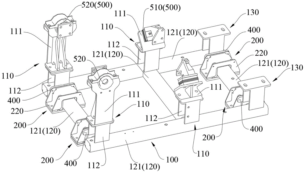
Figure 202010018518

The invention provides a vibration damping component of a power source and an engineering vehicle. The vibration damping component comprises: a support frame for fixing the power source; a cavity, the support frame is supported on the vibration damping seat through the accommodating cavity; and a first vibration damping pad is arranged in the accommodating cavity and is located between the vibration damping base and the support frame. In the vibration-damping assembly of the power source, a support frame and a vibration-damping seat are arranged between the power source and the bearing member of the power source, the vibration-absorbing seat is fixed on the bearing member of the power source, and the support frame is used to fix the engine; the support frame passes through The accommodating cavity on the shock-absorbing seat is in contact with the first shock-absorbing pad in the accommodating cavity. The vibration damping assembly can transmit the vibration of the power source to the support frame to be greatly reduced by the first vibration damping pad between the support frame and the vibration damping seat, thereby reducing the vibration transmitted from the power source to the bearing member, and improving the bearing member’s vibration. stability.

Figure 202010018518

Description

Vibration reduction assembly of power source and engineering vehicle
Technical Field
The invention relates to the technical field of engine vibration reduction, in particular to a vibration reduction assembly of a power source and an engineering vehicle.
Background
In an existing engineering vehicle, for example, a concrete pump truck, a fire truck, an airplane deicing vehicle, and the like, an engine is fixedly mounted on a frame, and a damping elastic body is generally disposed between the engine and the frame to damp the engine. However, the vibration damping method can only prevent a small part of vibration from being transmitted to the frame under the action of the vibration damping elastomer, and the vibration damping requirement of an engine cannot be met on some engineering vehicles.
Disclosure of Invention
The invention aims to provide a vibration reduction assembly of a power source and an engineering vehicle, and aims to solve the technical problem that the power source cannot meet the vibration reduction requirement of the power source through the existing vibration reduction structure in the prior art.
In order to achieve the purpose, the technical scheme of the invention is realized as follows:
the invention provides a vibration damping assembly of a power source, comprising: the support frame is used for fixing the power source; the vibration reduction seat is arranged on a bearing piece of the power source, an accommodating cavity is formed in the vibration reduction seat, and the support frame is supported on the vibration reduction seat through the accommodating cavity; and the first vibration damping pad is arranged in the accommodating cavity and is positioned between the vibration damping seat and the supporting frame.
Further, the support frame includes: the first supporting seat is used for fixing an engine of the power source; and the underframe comprises a plurality of beam bodies forming a frame structure, the first supporting seat is connected with the beam bodies, the beam bodies are supported on the vibration damping seat through the containing cavities, and the first vibration damping pad is positioned between the vibration damping seat and the beam bodies.
Furthermore, a plurality of the beam bodies are connected to form a square frame, and two of the beam bodies which are arranged opposite to the square frame are respectively supported on at least two of the vibration damping seats.
Further, the support frame includes the second supporting seat that is used for fixing the radiator of power supply, the second supporting seat with the roof beam body coupling, the second supporting seat with first supporting seat is in the interval sets up on the roof beam body.
Further, the first support base includes: an upper support for supporting the engine; and the lower support is arranged on the beam body and is connected with the upper support.
Further, the vibration damping assembly further comprises a vibration isolator arranged between the vibration damping seat and the first supporting seat.
Further, the vibration damping mount includes: the bottom plate is connected with the bearing piece, and a limiting cavity is formed in the bottom plate; the base is connected with the bottom plate, and the base and the bottom plate enclose the accommodating cavity; the first vibration damping pad comprises a first elastic body and a second elastic body, the first elastic body is arranged in the limiting cavity, the second elastic body is arranged in the containing cavity and located on the side of the base, and the first elastic body and the second elastic body are arranged in an enclosing mode.
Further, the vibration damping assembly further comprises a second vibration damping pad arranged between the power source and the support frame.
Further, the second vibration damping pad comprises a flat pad and a ring pad, the flat pad is arranged on one side, close to the radiator, of the engine of the power source, and the ring pad is arranged on one side, far away from the radiator, of the engine of the power source.
According to the second aspect of the invention, the engineering vehicle comprises a power source and the vibration damping assembly, wherein the power source is mounted on the vibration damping assembly.
According to the vibration reduction assembly of the power source, the support frame and the vibration reduction seat are arranged between the power source and the bearing piece of the power source, the vibration reduction seat is fixed on the bearing piece of the power source, and the support frame is used for fixing an engine; the support frame passes the chamber that holds on the damping seat and with hold the first damping pad butt in the intracavity. The vibration damping subassembly can reduce the vibration that the power supply transmitted to the support frame by a wide margin through the first damping pad between support frame and the damping seat to reduce the vibration that the power supply transmitted to bearing piece, improve bearing piece's stability.
Drawings
FIG. 1 is a schematic structural diagram of a vibration damping assembly of a power source according to an embodiment of the present disclosure;
FIG. 2 is a layout view of the vibration dampening shoe shown in FIG. 1;
FIG. 3 is a cross-sectional view of the vibration dampening shoe shown in FIG. 1;
fig. 4 is an enlarged view of a portion a in fig. 3.
Description of reference numerals:
100. a support frame; 110. a first support base; 111. an upper support; 112. a lower support; 120. a chassis; 121. a beam body; 130. a second support seat;
200. a vibration damping seat; 210. a base plate; 220. a base;
300. a first vibration damping pad; 310. a first elastic body; 320. a second elastomer;
400. a vibration isolator;
500. a second vibration damping pad; 510. flattening the cushion; 520. and (5) a ring pad.
Detailed Description
The present invention will be described in further detail with reference to the accompanying drawings and specific embodiments. The descriptions of "first", "second", etc. in the present invention are for descriptive purposes only and are not to be construed as indicating or implying relative importance or implying any number or order of technical features indicated. Thus, a feature defined as "first" or "second" may explicitly or implicitly include at least one such feature. In the description of the present invention, "a plurality" means at least two, e.g., two, three, etc., unless specifically limited otherwise.
Referring to fig. 1, in a first aspect of an embodiment of the present application, there is provided a vibration damping assembly of a power source, including a support bracket 100 for fixing the power source; the vibration damping seat 200 is installed on a bearing part of a power source, an accommodating cavity is formed on the vibration damping seat 200, and the support frame 100 is supported on the vibration damping seat 200 through the accommodating cavity; and a first damping pad 300 disposed in the accommodating chamber and located between the damping mount 200 and the supporting frame 100.
The power source is generally directly and fixedly mounted on the bearing member, for example, an engine of the deicing vehicle is mounted on a frame of the deicing vehicle, and since the power source generates large vibration during operation, the vibration is transmitted to the bearing member, so that the bearing member also generates large vibration, which affects the stability of the bearing member. The power source generally includes two parts, an engine and a radiator for the engine. The vibration of the engine and the radiator is transmitted to the bearing part and influences the stability of the bearing part.
The vibration damping assembly of the power source of the embodiment of the application is provided with a support frame 100 for fixing the power source and a vibration damping seat 200 for bearing the support frame 100, and the vibration damping seat 200 is arranged on a bearing piece of the power source; wherein, damping seat 200 is provided with and holds the chamber, holds the first damping pad 300 of intracavity installation, and support frame 100 passes and holds the chamber and bear on damping seat 200, first damping pad 300 respectively with damping seat 200, support frame 100 butt.
In the embodiment of the present application, the vibration of the power source is first transmitted to the supporting frame 100, and then the vibration transmitted from the supporting frame 100 to the vibration damping base 200 is greatly reduced through the first vibration damping pad 300 between the supporting frame 100 and the vibration damping base 200, so that the vibration transmitted from the power source bearing member is also greatly reduced, thereby improving the stability of the bearing member.
It is understood that the supporting frame 100 may be the oppositely disposed beams 121, or may be a frame structure formed by connecting the beams 121 end to end. The beam 121 is disposed through the damping seat 200, and one or two of the oppositely disposed beams 121 may be borne on the damping seat 200, or one or more beams 121 enclosing a frame structure may be borne on the damping seat 200. That is, at least one beam 121 is inserted into the damping seat 200, that is, some beams 121 are installed on the damping seat 200, and some beams 121 do not need to be supported by the damping seat 200. The number of the damping seats 200 penetrating through each beam body 121 may be one or more.
In the embodiment of the present application, the first damping pad 300 is disposed on the inner wall corresponding to the accommodating cavity, and is attached to the inner wall. After the supporting frame 100 passes through the accommodating cavity, the first damping pad 300 is abutted to the damping pad and the supporting frame 100 at the same time, so that the vibration transmission between the supporting frame 100 and the damping seat 200 is reduced.
In some embodiments, the support stand 100 includes a first support base 110 for fixing an engine of a power source; and the underframe 120 comprises a plurality of beams 121 forming a frame structure, the first supporting seat 110 is connected with the beams 121, the beams 121 are supported on the damping seat 200 through the accommodating cavities, and the first damping pad 300 is positioned between the damping seat 200 and the beams 121.
In the embodiment of the present application, the supporting frame 100 includes a first supporting seat 110 and a bottom frame 120, and the bottom frame 120 is a frame structure formed by connecting a plurality of beam bodies 121. The first supporting seat 110 is installed on the beam body 121 of the underframe 120 for fixing the engine, and the beam body 121 passes through the receiving cavity of the damping seat 200 and abuts against the first damping pad 300. It can be understood that the engine is fixed on the first supporting seat 110, rather than directly on the beam 121 of the chassis 120, so as to avoid the engine interfering with the damping seat 200 penetrating through the beam 121.
Further, the first support base 110 includes an upper support 111 for supporting the engine; and a lower support 112 provided on the beam body 121 and connected to the upper support 111. As can be appreciated, on the one hand, the lower support 112 serves to increase the distance between the engine and the beam 121 of the undercarriage 120, reducing the vibrations transmitted by the engine to the undercarriage 120; on the other hand, in order to avoid interference between the radiator and the damper base 200, the radiator is not directly fixed to the base frame 120, and the lower support 112 serves to match the height positions of the engine and the radiator. In addition, referring to fig. 1, in order to reduce weight, the lower support 112 is generally provided as a frame body having a certain height, which is not strong, and the weight of the entire engine is large, and the lower support 112 cannot solely bear the weight of the engine, so that the upper support 111 is further provided to bear the weight of the engine, thereby improving the stability of the engine.
In addition, the underframe 120 is a frame structure, so that compared with the beam bodies 121 which are not connected and oppositely arranged, the support performance for the engine is better, and the engine is more stably arranged on the underframe 120; on the other hand, the frame structure makes the vibration transmitted from the engine to the underframe 120 disperse more uniformly, and can have better vibration damping effect. Further, a plurality of beams 121 are connected to form a square frame, and two beams 121 arranged opposite to the square frame are respectively supported on at least two vibration damping bases 200. That is, referring to fig. 2, the damping seats 200 are preferably used for carrying two opposite beams 121, and the number of the damping seats 200 selected for each beam 121 is at least two. Damping seat 200 sets up relatively and installs in pairs, can reduce the vibration that roof beam body 121 transmitted to damping seat 200 more effectively, improves damping assembly's damping performance.
In some embodiments, the supporting frame 100 includes a second supporting seat 130 for fixing a heat sink of the power source, the second supporting seat 130 is connected to the beam 121, and the second supporting seat 130 and the first supporting seat 110 are spaced apart from each other on the beam 121. That is, the beam 121 of the bottom frame 120 is further mounted with a second support seat 130 for fixing a heat sink, and the vibration transmitted from the heat sink to the carrier is also reduced by the first damping pad 300 between the beam 121 and the damping seat 200. In addition, the heat sink is mounted on the beam 121 of the bottom chassis 120 through the second support seat 130, not directly mounted on the beam 121, also to avoid interference between the heat sink and the vibration damping seat 200 on the beam 121. Again, the second support base 130 functions in the same manner as the lower support 112 provided below the engine, i.e., by increasing the distance between the radiator and the beam 121, the vibration transmitted from the radiator to the beam 121 is reduced. The second supporting seat 130 is spaced apart from the first supporting seat 110 on the beam 121, so as to avoid mutual interference between the engine and the radiator during installation.
In some embodiments, the vibration damping assembly further comprises a vibration isolator 400 disposed between the vibration damping mount 200 and the first support mount 110. It is understood that the vibration isolator 400 for vibration damping is also disposed between the first support seat 110 and the vibration damping seat 200, so that the vibration transmitted from the engine to the underframe 120 can be further reduced, and the vibration damping performance of the vibration damping assembly can be further improved. Similarly, the vibration isolator 400 may be disposed between the vibration damping mount 200 and the second support mount 130, so as to reduce the vibration transmitted to the bottom frame 120 on the heat sink, which also improves the vibration damping performance of the vibration damping assembly.
In some embodiments, the vibration dampening shoe 200 comprises: the bottom plate 210 is connected with the bearing piece, and a limit cavity is formed in the bottom plate 210; and a base 220 connected with the bottom plate 210, the base 220 and the bottom plate 210 enclosing a containing cavity; the first vibration damping pad 300 includes a first elastic body 310 and a second elastic body 320, the first elastic body 310 is disposed in the limiting cavity, the second elastic body 320 is disposed in the accommodating cavity and located on the side of the base 220, and the first elastic body 310 and the second elastic body 320 are surrounded.
As can be understood, referring to fig. 3 and 4, the damping seat 200 is separately provided as a bottom plate 210 and a base 220, and the bottom plate 210 and the base 220 enclose to form an accommodating cavity, when the damping seat is installed, the bottom plate 210 may be fixed on a bearing of a power source, the beam body 121 may be placed on the bottom plate 210, and finally the base 220 may be placed above the beam body 121 and fix the bottom plate 210 and the base 220. The above scheme facilitates the installation of the beam body 121 in the accommodating cavity. A limiting cavity is formed on the bottom plate 210, and the first elastic body 310 is arranged in the limiting cavity; the second elastic body 320 is disposed along the inner wall of the base 220, and the first elastic body 310 and the second elastic body 320 are disposed in a surrounding manner, that is, the first elastic body 310 and the second elastic body 320 are disposed on the peripheral side of the inner wall corresponding to the accommodating cavity, and can be completely wrapped between the vibration damping seat 200 and the beam body 121, so as to more effectively reduce the vibration transmitted from the beam body 121 to the vibration damping seat 200, and improve the vibration damping effect of the vibration damping assembly.
In some embodiments, the vibration damping assembly further includes a second vibration damping pad 500 disposed between the power source and the support bracket 100. That is, in addition to the first damping pad 300 provided between the damping mount 200 and the support frame 100 of the power source, a second damping pad 500 may be provided between the support frame 100 and the power source. Second damping pad 500 can reduce the vibration that the power supply transmitted to support frame 100 to reduce the vibration that support frame 100 transmitted to damping seat 200, finally make the vibration that transmits to power supply carrier reduce, improved the damping performance of damping subassembly, promoted the stability that holds carrier. Specifically, the second vibration damping pad 500 is disposed between the engine and the upper support 111. Referring to fig. 1, the second damping pad 500 may not be disposed between the heat sink and the second support base 130.
In general, the second damping pad 500 may be provided in any shape that may exert a damping effect. Further, referring to fig. 1, the second vibration damping pad 500 includes a flat pad 510 and a ring pad 520, the flat pad 510 is disposed on a side of the engine of the power source close to the radiator, and the ring pad 520 is disposed on a side of the engine of the power source away from the radiator. It is understood that the second vibration damping pad 500 is disposed between the engine and the support bracket 100, and the shape of the second vibration damping pad 500 disposed between the support bracket 100 at the front end and the rear end and the engine is different due to the different weights of the front end and the rear end of the engine. The rear end of the engine is heavier and is connected with the pump, so that the rear end of the engine vibrates more seriously, and the second vibration damping pad 500 at the rear end is annular, so that the vibration damping effect in any direction is good; the vibration of the front end of the engine is relatively small, and thus a certain vibration damping effect can be achieved with the simple flat pad 510.
In a second aspect of the embodiments of the present application, there is also provided an engineering vehicle, including a power source and any one of the above-mentioned vibration damping assemblies, wherein the power source is mounted on the vibration damping assembly. Since the above-mentioned damping assembly has the technical effects described above, the engineering vehicle having the damping assembly also has corresponding technical effects, and the details are not described herein.
The above description is only an embodiment of the present invention, but the scope of the present invention is not limited thereto, and any person skilled in the art can easily conceive of changes or substitutions within the technical scope of the present invention, and all such changes or substitutions are included in the scope of the present invention. Moreover, the technical solutions in the embodiments of the present invention may be combined with each other, but it is necessary to be able to be realized by a person skilled in the art, and when the technical solutions are contradictory or cannot be realized, the combination of the technical solutions should be considered to be absent, and is not within the protection scope of the present invention. Therefore, the protection scope of the present invention shall be subject to the protection scope of the appended claims.

Claims (9)

1.一种动力源的减振组件,其特征在于,包括:1. a vibration damping assembly of a power source, characterized in that, comprising: 支撑架,用于固定所述动力源;a support frame for fixing the power source; 减振座,安装于所述动力源的承载件上,所述减振座上形成有容纳腔,所述支撑架通过所述容纳腔支撑在所述减振座上;以及a vibration-damping seat, mounted on the bearing member of the power source, a accommodating cavity is formed on the vibration-damping seat, and the support frame is supported on the vibration-damping seat through the accommodating cavity; and 第一减振垫,设置于所述容纳腔内,包覆于所述减振座与所述支撑架之间;a first vibration damping pad, disposed in the accommodating cavity, and wrapped between the vibration damping seat and the support frame; 第二减振垫,设置在所述动力源与所述支撑架之间。A second vibration damping pad is provided between the power source and the support frame. 2.根据权利要求1所述的减振组件,其特征在于,所述支撑架包括:2. The vibration damping assembly according to claim 1, wherein the support frame comprises: 第一支撑座,用于固定所述动力源的发动机;以及a first support seat for securing the engine of the power source; and 底架,包括形成框架结构的多个梁体,所述第一支撑座与所述梁体连接,所述梁体通过所述容纳腔支撑在所述减振座上,所述第一减振垫位于所述减振座与所述梁体之间。The chassis includes a plurality of beam bodies forming a frame structure, the first support base is connected with the beam bodies, the beam body is supported on the vibration damping base through the accommodating cavity, and the first vibration damping base is A pad is located between the vibration damping seat and the beam body. 3.根据权利要求2所述的减振组件,其特征在于,多个所述梁体连接形成方形框架,所述方形框架相对设置的两个所述梁体分别支撑在至少两个所述减振座上。3 . The vibration damping assembly according to claim 2 , wherein a plurality of the beam bodies are connected to form a square frame, and the two beam bodies arranged opposite to the square frame are respectively supported on at least two of the dampers. 4 . on the vibrating seat. 4.根据权利要求2所述的减振组件,其特征在于,所述支撑架包括用于固定所述动力源的散热器的第二支撑座,所述第二支撑座与所述梁体连接,所述第二支撑座与所述第一支撑座在所述梁体上间隔设置。4 . The vibration damping assembly according to claim 2 , wherein the support frame comprises a second support seat for fixing the radiator of the power source, and the second support seat is connected with the beam body. 5 . , the second support seat and the first support seat are arranged at intervals on the beam body. 5.根据权利要求2所述的减振组件,其特征在于,所述第一支撑座包括:5. The vibration damping assembly according to claim 2, wherein the first support seat comprises: 上部支撑,用于支撑所述发动机;以及an upper support for supporting the engine; and 下部支撑,设置在所述梁体上,与所述上部支撑连接。The lower support is arranged on the beam body and is connected with the upper support. 6.根据权利要求2所述的减振组件,其特征在于,所述减振组件还包括设置在所述减振座与所述第一支撑座之间的隔振垫。6 . The vibration damping assembly according to claim 2 , wherein the vibration damping assembly further comprises a vibration isolation pad disposed between the vibration damping seat and the first support seat. 7 . 7.根据权利要求1所述的减振组件,其特征在于,所述减振座包括:7. The damping assembly of claim 1, wherein the damping seat comprises: 底板,与所述承载件连接,所述底板形成有限位腔;以及a bottom plate connected to the carrier, the bottom plate forming a limiting cavity; and 底座,与所述底板连接,所述底座和所述底板围合成所述容纳腔;a base, connected with the bottom plate, and the base and the bottom plate are enclosed to form the accommodating cavity; 所述第一减振垫包括第一弹性体和第二弹性体,所述第一弹性体设置在所述限位腔内,所述第二弹性体设置在容纳腔内并位于所述底座侧,所述第一弹性体和所述第二弹性体围设设置。The first vibration damping pad includes a first elastic body and a second elastic body, the first elastic body is arranged in the limiting cavity, and the second elastic body is arranged in the accommodating cavity and is located on the side of the base , the first elastic body and the second elastic body are arranged around. 8.根据权利要求1所述的减振组件,其特征在于,所述第二减振垫包括平垫和环垫,所述平垫设置于所述动力源的发动机靠近所述动力源的散热器的一侧,所述环垫设置于所述发动机远离所述散热器的一侧。8 . The vibration damping assembly according to claim 1 , wherein the second vibration damping pad comprises a flat pad and a ring pad, and the flat pad is disposed on the engine of the power source close to the heat dissipation of the power source. 9 . one side of the radiator, the ring gasket is arranged on the side of the engine away from the radiator. 9.一种工程车辆,其特征在于,包括动力源和权利要求1~8任意一项所述的减振组件,所述动力源安装在所述减振组件上。9 . An engineering vehicle, characterized by comprising a power source and the vibration damping assembly according to any one of claims 1 to 8 , wherein the power source is mounted on the vibration damping assembly. 10 .
CN202010018518.3A 2020-01-08 2020-01-08 Vibration reduction assembly of power source and engineering vehicle Active CN111237382B (en)

Priority Applications (1)

Application Number Priority Date Filing Date Title
CN202010018518.3A CN111237382B (en) 2020-01-08 2020-01-08 Vibration reduction assembly of power source and engineering vehicle

Applications Claiming Priority (1)

Application Number Priority Date Filing Date Title
CN202010018518.3A CN111237382B (en) 2020-01-08 2020-01-08 Vibration reduction assembly of power source and engineering vehicle

Publications (2)

Publication Number Publication Date
CN111237382A CN111237382A (en) 2020-06-05
CN111237382B true CN111237382B (en) 2022-03-04

Family

ID=70874414

Family Applications (1)

Application Number Title Priority Date Filing Date
CN202010018518.3A Active CN111237382B (en) 2020-01-08 2020-01-08 Vibration reduction assembly of power source and engineering vehicle

Country Status (1)

Country Link
CN (1) CN111237382B (en)

Citations (8)

* Cited by examiner, † Cited by third party
Publication number Priority date Publication date Assignee Title
US5088572A (en) * 1991-03-28 1992-02-18 Navistar International Transportation Corp. Forward control bus chassis with low engine mounting assembly
CN203623362U (en) * 2013-12-26 2014-06-04 安徽江淮汽车股份有限公司 Engine suspension assembly
CN203651434U (en) * 2013-12-31 2014-06-18 一重集团大连设计研究院有限公司 Power assembly mounting rack for self-unloading vehicle having electric wheels for mines
CN203996522U (en) * 2014-05-30 2014-12-10 天津柳工机械有限公司 The shock attenuation unit of crawler type traveling machine chassis system
CN105857049A (en) * 2016-05-10 2016-08-17 徐州徐工矿山机械有限公司 Electric drive mining dump truck power support
CN205768653U (en) * 2016-05-31 2016-12-07 安徽柳工起重机有限公司 Auxiliary supporting device for gearbox
CN107009875A (en) * 2017-03-27 2017-08-04 安徽江淮汽车集团股份有限公司 Frame for fixing heat sink
CN209096450U (en) * 2018-09-17 2019-07-12 奇瑞商用车(安徽)有限公司 A kind of suspension type electric vehicle suspension system

Family Cites Families (1)

* Cited by examiner, † Cited by third party
Publication number Priority date Publication date Assignee Title
JPH08164753A (en) * 1994-12-11 1996-06-25 Mitsubishi Motors Corp Car body front structure

Patent Citations (8)

* Cited by examiner, † Cited by third party
Publication number Priority date Publication date Assignee Title
US5088572A (en) * 1991-03-28 1992-02-18 Navistar International Transportation Corp. Forward control bus chassis with low engine mounting assembly
CN203623362U (en) * 2013-12-26 2014-06-04 安徽江淮汽车股份有限公司 Engine suspension assembly
CN203651434U (en) * 2013-12-31 2014-06-18 一重集团大连设计研究院有限公司 Power assembly mounting rack for self-unloading vehicle having electric wheels for mines
CN203996522U (en) * 2014-05-30 2014-12-10 天津柳工机械有限公司 The shock attenuation unit of crawler type traveling machine chassis system
CN105857049A (en) * 2016-05-10 2016-08-17 徐州徐工矿山机械有限公司 Electric drive mining dump truck power support
CN205768653U (en) * 2016-05-31 2016-12-07 安徽柳工起重机有限公司 Auxiliary supporting device for gearbox
CN107009875A (en) * 2017-03-27 2017-08-04 安徽江淮汽车集团股份有限公司 Frame for fixing heat sink
CN209096450U (en) * 2018-09-17 2019-07-12 奇瑞商用车(安徽)有限公司 A kind of suspension type electric vehicle suspension system

Also Published As

Publication number Publication date
CN111237382A (en) 2020-06-05

Similar Documents

Publication Publication Date Title
JP6301385B2 (en) Engine mount structure
JP5467525B2 (en) Support structure for vehicle coolant reserve tank
CN205381134U (en) Engine mounting structure and car
CN102562935A (en) Vibration-proof device and fixing device of air conditioner outdoor unit with same
KR102522291B1 (en) Suspension apparatus for vehicle
JP2019044871A (en) Vibration control structure
JPS6323271Y2 (en)
CN111237382B (en) Vibration reduction assembly of power source and engineering vehicle
CN206841152U (en) Engine suspension soft pad component and its assembly and vehicle
CN109027085B (en) A low frequency vibration isolator for high-speed train floor
CN212717753U (en) Automobile dynamic vibration absorber
US11027605B1 (en) Vibration attenuating engine mounting apparatus
CN206317688U (en) A kind of vibration damping rubber cushion of automobile radiators
CN216942650U (en) Support and mounting structure and vehicle
CN105667290A (en) Front suspension assembly for power assembly
CN107618351A (en) A kind of novel damping suspension
CN218031201U (en) Power suspension vibration absorber, power suspension vibration isolation and absorption assembly and automobile
CN207568708U (en) A kind of electric fuel punp shock-absorbing bracket
CN209414488U (en) Vehicle-mounted mobile power station rubber oleo-gear
CN223894574U (en) Integrated hydraulic oil tank
CN223821457U (en) Engine support convenient to damping
CN217969462U (en) Mounting structure of seat belt retractor and seat belt retractor device
CN111497941A (en) A subframe assembly and vehicle
JP2018054040A (en) Power plant mount structure
CN218536332U (en) Suspension structure for fuel cell and vehicle

Legal Events

Date Code Title Description
PB01 Publication
PB01 Publication
SE01 Entry into force of request for substantive examination
GR01 Patent grant
GR01 Patent grant
CP03 Change of name, title or address

Address after: Room 201, 2nd Floor, Office Building, No. 86 Xindian Road, Tianxin District, Changsha City, Hunan Province 410000

Patentee after: Hunan Shuangda Intelligent Equipment Co.,Ltd.

Country or region after: China

Address before: Room 201, water Hall integrated service building, 506 Qingyuan Road, Tianxin District, Changsha City, Hunan Province

Patentee before: HUNAN SHUANGDA ELECTROMECHANICAL Co.,Ltd.

Country or region before: China

CP03 Change of name, title or address
PE01 Entry into force of the registration of the contract for pledge of patent right

Denomination of invention: Power source vibration reduction component and engineering vehicle

Granted publication date: 20220304

Pledgee: Bank of China Limited Changsha Tianxin Branch

Pledgor: Hunan Shuangda Intelligent Equipment Co.,Ltd.

Registration number: Y2026980013186