CN111237444A - Work vehicle and shift control method for work vehicle - Google Patents
Work vehicle and shift control method for work vehicle Download PDFInfo
- Publication number
- CN111237444A CN111237444A CN201811608404.3A CN201811608404A CN111237444A CN 111237444 A CN111237444 A CN 111237444A CN 201811608404 A CN201811608404 A CN 201811608404A CN 111237444 A CN111237444 A CN 111237444A
- Authority
- CN
- China
- Prior art keywords
- clutch
- speed
- shift
- pressure
- low
- Prior art date
- Legal status (The legal status is an assumption and is not a legal conclusion. Google has not performed a legal analysis and makes no representation as to the accuracy of the status listed.)
- Granted
Links
- 238000000034 method Methods 0.000 title abstract description 16
- 230000005540 biological transmission Effects 0.000 claims abstract description 243
- 230000008859 change Effects 0.000 claims abstract description 28
- 239000003921 oil Substances 0.000 claims description 16
- 239000010720 hydraulic oil Substances 0.000 claims description 12
- 230000003247 decreasing effect Effects 0.000 claims description 9
- 230000035939 shock Effects 0.000 abstract description 8
- 230000001629 suppression Effects 0.000 description 10
- 230000035945 sensitivity Effects 0.000 description 7
- 238000010586 diagram Methods 0.000 description 6
- 230000001133 acceleration Effects 0.000 description 5
- 230000000694 effects Effects 0.000 description 3
- 230000007246 mechanism Effects 0.000 description 3
- XLYOFNOQVPJJNP-UHFFFAOYSA-N water Substances O XLYOFNOQVPJJNP-UHFFFAOYSA-N 0.000 description 3
- 238000002788 crimping Methods 0.000 description 2
- 230000007423 decrease Effects 0.000 description 2
- 230000007935 neutral effect Effects 0.000 description 2
- 230000008569 process Effects 0.000 description 2
- 239000000470 constituent Substances 0.000 description 1
- 230000000881 depressing effect Effects 0.000 description 1
- 238000001514 detection method Methods 0.000 description 1
- 239000000446 fuel Substances 0.000 description 1
- 238000002347 injection Methods 0.000 description 1
- 239000007924 injection Substances 0.000 description 1
- 230000014759 maintenance of location Effects 0.000 description 1
- 239000000463 material Substances 0.000 description 1
- 230000004048 modification Effects 0.000 description 1
- 238000012986 modification Methods 0.000 description 1
- 239000010705 motor oil Substances 0.000 description 1
- 238000006467 substitution reaction Methods 0.000 description 1
- 230000007704 transition Effects 0.000 description 1
- 238000011144 upstream manufacturing Methods 0.000 description 1
Images


Classifications
-
- F—MECHANICAL ENGINEERING; LIGHTING; HEATING; WEAPONS; BLASTING
- F16—ENGINEERING ELEMENTS AND UNITS; GENERAL MEASURES FOR PRODUCING AND MAINTAINING EFFECTIVE FUNCTIONING OF MACHINES OR INSTALLATIONS; THERMAL INSULATION IN GENERAL
- F16H—GEARING
- F16H61/00—Control functions within control units of change-speed- or reversing-gearings for conveying rotary motion ; Control of exclusively fluid gearing, friction gearing, gearings with endless flexible members or other particular types of gearing
- F16H61/70—Control functions within control units of change-speed- or reversing-gearings for conveying rotary motion ; Control of exclusively fluid gearing, friction gearing, gearings with endless flexible members or other particular types of gearing specially adapted for change-speed gearing in group arrangement, i.e. with separate change-speed gear trains arranged in series, e.g. range or overdrive-type gearing arrangements
- F16H61/702—Control functions within control units of change-speed- or reversing-gearings for conveying rotary motion ; Control of exclusively fluid gearing, friction gearing, gearings with endless flexible members or other particular types of gearing specially adapted for change-speed gearing in group arrangement, i.e. with separate change-speed gear trains arranged in series, e.g. range or overdrive-type gearing arrangements using electric or electrohydraulic control means
-
- E—FIXED CONSTRUCTIONS
- E02—HYDRAULIC ENGINEERING; FOUNDATIONS; SOIL SHIFTING
- E02F—DREDGING; SOIL-SHIFTING
- E02F9/00—Component parts of dredgers or soil-shifting machines, not restricted to one of the kinds covered by groups E02F3/00 - E02F7/00
- E02F9/20—Drives; Control devices
- E02F9/22—Hydraulic or pneumatic drives
- E02F9/2253—Controlling the travelling speed of vehicles, e.g. adjusting travelling speed according to implement loads, control of hydrostatic transmission
-
- F—MECHANICAL ENGINEERING; LIGHTING; HEATING; WEAPONS; BLASTING
- F16—ENGINEERING ELEMENTS AND UNITS; GENERAL MEASURES FOR PRODUCING AND MAINTAINING EFFECTIVE FUNCTIONING OF MACHINES OR INSTALLATIONS; THERMAL INSULATION IN GENERAL
- F16D—COUPLINGS FOR TRANSMITTING ROTATION; CLUTCHES; BRAKES
- F16D25/00—Fluid-actuated clutches
- F16D25/12—Details not specific to one of the before-mentioned types
- F16D25/14—Fluid pressure control
-
- F—MECHANICAL ENGINEERING; LIGHTING; HEATING; WEAPONS; BLASTING
- F16—ENGINEERING ELEMENTS AND UNITS; GENERAL MEASURES FOR PRODUCING AND MAINTAINING EFFECTIVE FUNCTIONING OF MACHINES OR INSTALLATIONS; THERMAL INSULATION IN GENERAL
- F16H—GEARING
- F16H61/00—Control functions within control units of change-speed- or reversing-gearings for conveying rotary motion ; Control of exclusively fluid gearing, friction gearing, gearings with endless flexible members or other particular types of gearing
- F16H61/02—Control functions within control units of change-speed- or reversing-gearings for conveying rotary motion ; Control of exclusively fluid gearing, friction gearing, gearings with endless flexible members or other particular types of gearing characterised by the signals used
-
- E—FIXED CONSTRUCTIONS
- E02—HYDRAULIC ENGINEERING; FOUNDATIONS; SOIL SHIFTING
- E02F—DREDGING; SOIL-SHIFTING
- E02F9/00—Component parts of dredgers or soil-shifting machines, not restricted to one of the kinds covered by groups E02F3/00 - E02F7/00
- E02F9/20—Drives; Control devices
- E02F9/22—Hydraulic or pneumatic drives
- E02F9/226—Safety arrangements, e.g. hydraulic driven fans, preventing cavitation, leakage, overheating
-
- F—MECHANICAL ENGINEERING; LIGHTING; HEATING; WEAPONS; BLASTING
- F16—ENGINEERING ELEMENTS AND UNITS; GENERAL MEASURES FOR PRODUCING AND MAINTAINING EFFECTIVE FUNCTIONING OF MACHINES OR INSTALLATIONS; THERMAL INSULATION IN GENERAL
- F16D—COUPLINGS FOR TRANSMITTING ROTATION; CLUTCHES; BRAKES
- F16D25/00—Fluid-actuated clutches
- F16D25/10—Clutch systems with a plurality of fluid-actuated clutches
-
- F—MECHANICAL ENGINEERING; LIGHTING; HEATING; WEAPONS; BLASTING
- F16—ENGINEERING ELEMENTS AND UNITS; GENERAL MEASURES FOR PRODUCING AND MAINTAINING EFFECTIVE FUNCTIONING OF MACHINES OR INSTALLATIONS; THERMAL INSULATION IN GENERAL
- F16D—COUPLINGS FOR TRANSMITTING ROTATION; CLUTCHES; BRAKES
- F16D35/00—Fluid clutches in which the clutching is predominantly obtained by fluid adhesion
-
- F—MECHANICAL ENGINEERING; LIGHTING; HEATING; WEAPONS; BLASTING
- F16—ENGINEERING ELEMENTS AND UNITS; GENERAL MEASURES FOR PRODUCING AND MAINTAINING EFFECTIVE FUNCTIONING OF MACHINES OR INSTALLATIONS; THERMAL INSULATION IN GENERAL
- F16H—GEARING
- F16H3/00—Toothed gearings for conveying rotary motion with variable gear ratio or for reversing rotary motion
- F16H3/02—Toothed gearings for conveying rotary motion with variable gear ratio or for reversing rotary motion without gears having orbital motion
- F16H3/08—Toothed gearings for conveying rotary motion with variable gear ratio or for reversing rotary motion without gears having orbital motion exclusively or essentially with continuously meshing gears, that can be disengaged from their shafts
-
- F—MECHANICAL ENGINEERING; LIGHTING; HEATING; WEAPONS; BLASTING
- F16—ENGINEERING ELEMENTS AND UNITS; GENERAL MEASURES FOR PRODUCING AND MAINTAINING EFFECTIVE FUNCTIONING OF MACHINES OR INSTALLATIONS; THERMAL INSULATION IN GENERAL
- F16H—GEARING
- F16H61/00—Control functions within control units of change-speed- or reversing-gearings for conveying rotary motion ; Control of exclusively fluid gearing, friction gearing, gearings with endless flexible members or other particular types of gearing
- F16H61/0021—Generation or control of line pressure
-
- F—MECHANICAL ENGINEERING; LIGHTING; HEATING; WEAPONS; BLASTING
- F16—ENGINEERING ELEMENTS AND UNITS; GENERAL MEASURES FOR PRODUCING AND MAINTAINING EFFECTIVE FUNCTIONING OF MACHINES OR INSTALLATIONS; THERMAL INSULATION IN GENERAL
- F16H—GEARING
- F16H61/00—Control functions within control units of change-speed- or reversing-gearings for conveying rotary motion ; Control of exclusively fluid gearing, friction gearing, gearings with endless flexible members or other particular types of gearing
- F16H61/02—Control functions within control units of change-speed- or reversing-gearings for conveying rotary motion ; Control of exclusively fluid gearing, friction gearing, gearings with endless flexible members or other particular types of gearing characterised by the signals used
- F16H61/0262—Control functions within control units of change-speed- or reversing-gearings for conveying rotary motion ; Control of exclusively fluid gearing, friction gearing, gearings with endless flexible members or other particular types of gearing characterised by the signals used the signals being hydraulic
- F16H61/0265—Control functions within control units of change-speed- or reversing-gearings for conveying rotary motion ; Control of exclusively fluid gearing, friction gearing, gearings with endless flexible members or other particular types of gearing characterised by the signals used the signals being hydraulic for gearshift control, e.g. control functions for performing shifting or generation of shift signals
-
- F—MECHANICAL ENGINEERING; LIGHTING; HEATING; WEAPONS; BLASTING
- F16—ENGINEERING ELEMENTS AND UNITS; GENERAL MEASURES FOR PRODUCING AND MAINTAINING EFFECTIVE FUNCTIONING OF MACHINES OR INSTALLATIONS; THERMAL INSULATION IN GENERAL
- F16H—GEARING
- F16H61/00—Control functions within control units of change-speed- or reversing-gearings for conveying rotary motion ; Control of exclusively fluid gearing, friction gearing, gearings with endless flexible members or other particular types of gearing
- F16H61/02—Control functions within control units of change-speed- or reversing-gearings for conveying rotary motion ; Control of exclusively fluid gearing, friction gearing, gearings with endless flexible members or other particular types of gearing characterised by the signals used
- F16H61/0262—Control functions within control units of change-speed- or reversing-gearings for conveying rotary motion ; Control of exclusively fluid gearing, friction gearing, gearings with endless flexible members or other particular types of gearing characterised by the signals used the signals being hydraulic
- F16H61/0276—Elements specially adapted for hydraulic control units, e.g. valves
-
- F—MECHANICAL ENGINEERING; LIGHTING; HEATING; WEAPONS; BLASTING
- F16—ENGINEERING ELEMENTS AND UNITS; GENERAL MEASURES FOR PRODUCING AND MAINTAINING EFFECTIVE FUNCTIONING OF MACHINES OR INSTALLATIONS; THERMAL INSULATION IN GENERAL
- F16H—GEARING
- F16H61/00—Control functions within control units of change-speed- or reversing-gearings for conveying rotary motion ; Control of exclusively fluid gearing, friction gearing, gearings with endless flexible members or other particular types of gearing
- F16H61/04—Smoothing ratio shift
-
- F—MECHANICAL ENGINEERING; LIGHTING; HEATING; WEAPONS; BLASTING
- F16—ENGINEERING ELEMENTS AND UNITS; GENERAL MEASURES FOR PRODUCING AND MAINTAINING EFFECTIVE FUNCTIONING OF MACHINES OR INSTALLATIONS; THERMAL INSULATION IN GENERAL
- F16H—GEARING
- F16H61/00—Control functions within control units of change-speed- or reversing-gearings for conveying rotary motion ; Control of exclusively fluid gearing, friction gearing, gearings with endless flexible members or other particular types of gearing
- F16H61/38—Control of exclusively fluid gearing
- F16H61/40—Control of exclusively fluid gearing hydrostatic
-
- B—PERFORMING OPERATIONS; TRANSPORTING
- B60—VEHICLES IN GENERAL
- B60Y—INDEXING SCHEME RELATING TO ASPECTS CROSS-CUTTING VEHICLE TECHNOLOGY
- B60Y2200/00—Type of vehicle
- B60Y2200/20—Off-Road Vehicles
- B60Y2200/22—Agricultural vehicles
- B60Y2200/221—Tractors
-
- F—MECHANICAL ENGINEERING; LIGHTING; HEATING; WEAPONS; BLASTING
- F16—ENGINEERING ELEMENTS AND UNITS; GENERAL MEASURES FOR PRODUCING AND MAINTAINING EFFECTIVE FUNCTIONING OF MACHINES OR INSTALLATIONS; THERMAL INSULATION IN GENERAL
- F16H—GEARING
- F16H3/00—Toothed gearings for conveying rotary motion with variable gear ratio or for reversing rotary motion
- F16H3/02—Toothed gearings for conveying rotary motion with variable gear ratio or for reversing rotary motion without gears having orbital motion
- F16H3/08—Toothed gearings for conveying rotary motion with variable gear ratio or for reversing rotary motion without gears having orbital motion exclusively or essentially with continuously meshing gears, that can be disengaged from their shafts
- F16H2003/0818—Toothed gearings for conveying rotary motion with variable gear ratio or for reversing rotary motion without gears having orbital motion exclusively or essentially with continuously meshing gears, that can be disengaged from their shafts comprising means for power-shifting
-
- F—MECHANICAL ENGINEERING; LIGHTING; HEATING; WEAPONS; BLASTING
- F16—ENGINEERING ELEMENTS AND UNITS; GENERAL MEASURES FOR PRODUCING AND MAINTAINING EFFECTIVE FUNCTIONING OF MACHINES OR INSTALLATIONS; THERMAL INSULATION IN GENERAL
- F16H—GEARING
- F16H3/00—Toothed gearings for conveying rotary motion with variable gear ratio or for reversing rotary motion
- F16H3/02—Toothed gearings for conveying rotary motion with variable gear ratio or for reversing rotary motion without gears having orbital motion
- F16H3/08—Toothed gearings for conveying rotary motion with variable gear ratio or for reversing rotary motion without gears having orbital motion exclusively or essentially with continuously meshing gears, that can be disengaged from their shafts
- F16H2003/0826—Toothed gearings for conveying rotary motion with variable gear ratio or for reversing rotary motion without gears having orbital motion exclusively or essentially with continuously meshing gears, that can be disengaged from their shafts wherein at least one gear on the input shaft, or on a countershaft is used for two different forward gear ratios
-
- F—MECHANICAL ENGINEERING; LIGHTING; HEATING; WEAPONS; BLASTING
- F16—ENGINEERING ELEMENTS AND UNITS; GENERAL MEASURES FOR PRODUCING AND MAINTAINING EFFECTIVE FUNCTIONING OF MACHINES OR INSTALLATIONS; THERMAL INSULATION IN GENERAL
- F16H—GEARING
- F16H61/00—Control functions within control units of change-speed- or reversing-gearings for conveying rotary motion ; Control of exclusively fluid gearing, friction gearing, gearings with endless flexible members or other particular types of gearing
- F16H61/04—Smoothing ratio shift
- F16H2061/0455—Smoothing ratio shift during shifts involving three or more shift members, e.g. release of 3-4 clutch, 2-4 brake and apply of forward clutch C1
-
- F—MECHANICAL ENGINEERING; LIGHTING; HEATING; WEAPONS; BLASTING
- F16—ENGINEERING ELEMENTS AND UNITS; GENERAL MEASURES FOR PRODUCING AND MAINTAINING EFFECTIVE FUNCTIONING OF MACHINES OR INSTALLATIONS; THERMAL INSULATION IN GENERAL
- F16H—GEARING
- F16H2200/00—Transmissions for multiple ratios
- F16H2200/003—Transmissions for multiple ratios characterised by the number of forward speeds
- F16H2200/0043—Transmissions for multiple ratios characterised by the number of forward speeds the gear ratios comprising four forward speeds
-
- F—MECHANICAL ENGINEERING; LIGHTING; HEATING; WEAPONS; BLASTING
- F16—ENGINEERING ELEMENTS AND UNITS; GENERAL MEASURES FOR PRODUCING AND MAINTAINING EFFECTIVE FUNCTIONING OF MACHINES OR INSTALLATIONS; THERMAL INSULATION IN GENERAL
- F16H—GEARING
- F16H2200/00—Transmissions for multiple ratios
- F16H2200/003—Transmissions for multiple ratios characterised by the number of forward speeds
- F16H2200/006—Transmissions for multiple ratios characterised by the number of forward speeds the gear ratios comprising eight forward speeds
Landscapes
- Engineering & Computer Science (AREA)
- General Engineering & Computer Science (AREA)
- Mechanical Engineering (AREA)
- Mining & Mineral Resources (AREA)
- Civil Engineering (AREA)
- Structural Engineering (AREA)
- Physics & Mathematics (AREA)
- Fluid Mechanics (AREA)
- Control Of Transmission Device (AREA)
Abstract
本发明提供作业车辆以及作业车辆的变速方法,能够尽可能地减少变速时的变速冲击以改善变速感觉。作业车辆具有:液压式的主变速离合器和Hi‑Lo离合器,它们设置在将动力向驱动轮传递的动力传递装置中;以及变速控制装置,其通过主变速离合器与Hi‑Lo离合器的组合对车速进行多挡变速控制。在从低速挡区域向使用了高速侧离合器的高速挡区域变速的升挡变速时,在变速完成之前,一边将高速侧离合器的压力保持在比低速侧离合器的压力高的第1压力(Pa),一边对作为变速源的主变速离合器的压力进行保持,从而通过高速侧离合器与作为变速源的主变速离合器的组合来传递动力。
The present invention provides a work vehicle and a shift method for the work vehicle, which can reduce the shift shock during shifting as much as possible to improve shifting feeling. The work vehicle has: a hydraulic main transmission clutch and a Hi-Lo clutch provided in a power transmission device that transmits power to the drive wheels; and a transmission control device that controls the vehicle speed by the combination of the main transmission clutch and the Hi-Lo clutch Multi-speed shift control. When shifting from the low speed range to the high speed range using the high speed clutch, the pressure of the high clutch is maintained at the first pressure (Pa) higher than the pressure of the low clutch until the speed change is completed. , the power is transmitted by the combination of the high-speed side clutch and the main transmission clutch as the transmission source while maintaining the pressure of the main transmission clutch as the transmission source.
Description
技术领域technical field
本发明涉及作业车辆以及作业车辆的变速控制方法。The present invention relates to a work vehicle and a shift control method for the work vehicle.
背景技术Background technique
以往,存在如下的作业车辆:该作业车辆通过利用液压工作的主变速离合器与高低离合器(Hi-Lo离合器)的组合来进行变速。在该作业车辆中,公知有如下的技术:在对主变速离合器和高低离合器同时进行切换的情况下,使作为变速源的高低离合器保持低压直至作为变速目标的主变速离合器上升至规定的压力,通过抑制动力被完全切断来抑制变速冲击(例如,参照专利文献1)。Conventionally, there has been a work vehicle that is shifted by a combination of a hydraulically operated main transmission clutch and a high-low clutch (Hi-Lo clutch). In such a work vehicle, a technique is known in which, when the main transmission clutch and the high and low clutch are switched at the same time, the high and low clutch, which is a transmission source, is kept at a low pressure until the main transmission clutch, which is a transmission target, rises to a predetermined pressure. The shift shock is suppressed by suppressing the power being completely cut off (for example, refer to Patent Document 1).
专利文献1:日本特开2016-125603号公报Patent Document 1: Japanese Patent Laid-Open No. 2016-125603
但是,在上述专利文献1所公开的技术中,在重载作业时仍有可能产生变速冲击。However, in the technique disclosed in the above-mentioned
发明内容SUMMARY OF THE INVENTION
本发明是鉴于上述情况而完成的,其目的在于,提供能够尽可能地减少变速时的变速冲击以改善变速感觉的作业车辆以及作业车辆的变速方法。The present invention has been made in view of the above circumstances, and an object of the present invention is to provide a work vehicle and a shift method for the work vehicle that can reduce the shifting shock during shifting as much as possible to improve the shifting feeling.
为了解决上述课题并达成目的,本发明的技术方案1所述的作业车辆1具有:动力传递装置13,其将来自发动机4的旋转动力向驱动轮2、3传递,所述动力传递装置13具有液压式的Hi-Lo离合器C以及与多个变速挡对应的多个液压式的主变速离合器B,该液压式的Hi-Lo离合器C具有高速侧离合器C1和低速侧离合器C2,能够在高速挡和低速挡之间进行变速,所述动力传递装置13构成为经由所述主变速离合器B和所述Hi-Lo离合器C进行传动;控制阀195、196、207、208,它们对所述主变速离合器B和所述Hi-Lo离合器C的压接状态进行调整;以及变速控制装置170,其通过所述主变速离合器B和所述Hi-Lo离合器C以能够多挡变速的方式对车速进行控制,在从使用了所述低速侧离合器C2的低速挡区域向使用了所述高速侧离合器C1的高速挡区域变速的升挡变速时,所述变速控制装置170进行如下控制:使所述低速侧离合器C2的压力下降,并且,一边将所述高速侧离合器C1的压力保持在比所述低速侧离合器C2的压力高的第1压力Pa,一边对作为变速源的所述主变速离合器B的压力进行保持,从而通过所述高速侧离合器C1与作为变速源的所述主变速离合器B的组合来传递动力,之后,使作为变速源的所述主变速离合器B的压力下降,使保持在所述第1压力Pa的所述高速侧离合器C1的压力上升,并且使作为变速目标的所述主变速离合器B的压力上升。In order to solve the above-mentioned problems and achieve the object, the
并且,技术方案2所述的发明的特征在于,在技术方案1所述的作业车辆1中,所述变速控制装置170具有作为变速目标的所述主变速离合器B的初始化时间Ta,作为变速目标的所述主变速离合器B的所述初始化时间Ta是根据作为变速目标的所述主变速离合器B达到规定的压力为止的基准时间而计算出的,在变速指示之后,在作为变速目标的所述主变速离合器B的初始化时间Ta的经过期间,以将工作油填充到用于使作为变速目标的所述主变速离合器B工作的油室211中的方式进行供给,所述变速控制装置170具有将所述高速侧离合器C1的压力保持在比所述低速侧离合器C2的压力高的第1压力Pa的时间和作为变速目标的所述主变速离合器B的初始化时间Ta所同时经过的期间S。Furthermore, the invention of
并且,技术方案3所述的发明的特征在于,作业车辆具有:动力传递装置13,其将来自发动机4的旋转动力向驱动轮2、3传递,所述动力传递装置13具有液压式的Hi-Lo离合器C以及与多个变速挡对应的多个液压式的主变速离合器B,该液压式的Hi-Lo离合器C具有高速侧离合器C1和低速侧离合器C2,能够在高速挡和低速挡之间进行变速,所述动力传递装置13构成为经由所述主变速离合器B和所述Hi-Lo离合器C进行传动;控制阀195、196、207、208,它们对所述主变速离合器B和所述Hi-Lo离合器C的压接状态进行调整;以及变速控制装置170,其通过所述主变速离合器B和所述Hi-Lo离合器C以能够多挡变速的方式对车速进行控制,在从使用了所述高速侧离合器C1的高速挡区域向使用了所述低速侧离合器C2的低速挡区域变速的降挡变速时,所述变速控制装置170进行如下控制:将所述高速侧离合器C1的压力保持在比所述低速侧离合器C2的压力高的第2压力Pb,在该高速侧离合器C1的压力保持期间,使作为变速源的所述主变速离合器B的压力下降,另一方面,使作为变速目标的所述主变速离合器B的压力开始上升,之后,使保持在所述第2压力Pb的所述高速侧离合器C1的压力下降,使所述低速侧离合器C2的压力上升。Furthermore, the invention described in
并且,技术方案4所述的发明的特征在于,在技术方案3所述的作业车辆1中,所述变速控制装置170具有所述低速侧离合器C2的初始化时间Td,所述低速侧离合器C2的所述初始化时间Td是根据所述低速侧离合器C2达到规定的压力为止的基准时间而计算出的,在变速指示之后,在所述初始化时间Td的经过期间,以将工作油填充到用于使所述低速侧离合器C2工作的油室211中的方式进行供给,在所述低速侧离合器C2的初始化时间Td的经过期间,使作为变速源的所述主变速离合器B的压力下降,另一方面,使作为变速目标的所述主变速离合器B的压力开始上升。Furthermore, the invention of
根据技术方案1所述的作业车辆,在与Hi-Lo离合器的从低速挡向高速挡切换相伴的变速中,以通过Hi-Lo离合器的高速侧离合器与主变速离合器的作为变速源的变速挡的组合进行动力传递的方式进行控制。即,Hi-Lo离合器和主变速离合器在从变速源切换到变速目标的期间通过作为高速挡的Hi-Lo离合器的变速目标侧与主变速离合器的变速源侧的组合来进行动力传递,从而能够抑制动力切断以获得良好的变速感觉。According to the work vehicle according to
根据技术方案2所述的作业车辆的作业车辆,除了技术方案1的发明效果之外,在Hi-Lo离合器的变速源侧的压力保持期间供给向作为变速目标的主变速离合器的油室填充的工作油,由此通过向在Hi-Lo离合器的变速源侧的压力保持结束之后填充也完成的主变速离合器的油室供给工作油,从而能够使主变速离合器的变速目标侧的压力快速上升,因此能够抑制动力切断以获得良好的变速感觉。According to the work vehicle of
根据技术方案3所述的作业车辆,在通过Hi-Lo离合器从高速挡向低速挡换挡的情况下,以通过Hi-Lo离合器的高速侧离合器与主变速离合器的作为变速目标的变速挡的组合进行动力传递的方式进行控制。即,Hi-Lo离合器和主变速离合器在从变速源切换到变速目标的期间通过作为高速挡的Hi-Lo离合器的变速源侧与主变速离合器的作为变速目标侧的变速挡的组合来进行动力传递,从而抑制动力切断以获得良好的变速感觉。According to the work vehicle described in
根据技术方案4所述的作业车辆的变速控制装置,除了技术方案3的发明效果之外,一边供给向Hi-Lo离合器的低速侧离合器的油室填充的工作油,一边使作为变速源的主变速离合器的压力下降,并且使作为变速目标的主变速离合器的压力开始上升,由此,通过向在使作为变速目标的所述主变速离合器的压力开始上升而对主变速离合器进行了切换之后填充也完成的Hi-Lo离合器的低速侧离合器的油室供给工作油,能够使Hi-Lo离合器的低速侧离合器的压力快速上升,因此能够抑制动力切断以获得良好的变速感觉。According to the gear shift control device for a work vehicle according to
附图说明Description of drawings
图1是作业车辆的概略侧视图。FIG. 1 is a schematic side view of a work vehicle.
图2是作业车辆的概略主视图。FIG. 2 is a schematic front view of the work vehicle.
图3是配置在变速箱内的变速装置的说明图。FIG. 3 is an explanatory diagram of a transmission arranged in a transmission.
图4是示出变速装置的动力传递路径的路线图。FIG. 4 is a road map showing a power transmission path of the transmission.
图5是示出多挡变速中的主变速离合器与Hi-Lo离合器的组合的表。FIG. 5 is a table showing combinations of the main transmission clutch and the Hi-Lo clutch in multi-speed shifting.
图6是作业车辆各部分的控制框图。6 is a control block diagram of each part of the work vehicle.
图7是离合器的液压回路图。FIG. 7 is a hydraulic circuit diagram of the clutch.
图8是与Hi-Lo离合器无关的变速控制的时序图。FIG. 8 is a timing chart of the shift control independent of the Hi-Lo clutch.
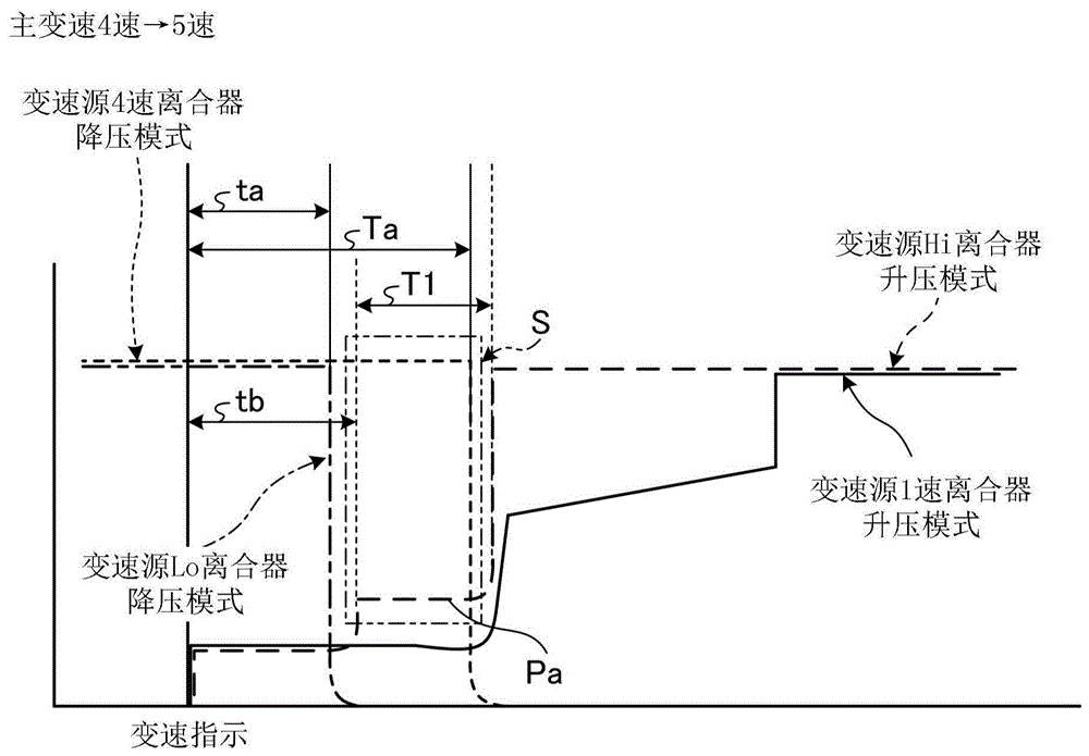
图9是示出从低速挡区域向高速挡区域的变速控制的一例的时序图。FIG. 9 is a timing chart showing an example of shift control from a low-speed range to a high-speed range.
图10是示出从高速挡区域向低速挡区域的变速控制的一例的时序图。FIG. 10 is a timing chart showing an example of shift control from a high-speed range to a low-speed range.
标号说明Label description
1:作业车辆(拖拉机);2:前轮;3:后轮;4:发动机;13:动力传递装置;170:行驶系统ECU(变速控制装置);171~176:压力传感器;195:比例控制阀(Hi离合器电磁阀);196:比例控制阀(Lo离合器电磁阀);201~206:离合器活塞;207:比例控制阀(1挡和3挡升压电磁阀);208:比例控制阀(2挡和4挡升压电磁阀);B:主变速离合器;C:Hi-Lo离合器;C1:高速侧离合器;C2:低速侧离合器;S:抑制期间;Pa:第1压力;Pb:第2压力;T1:第1时间;T2:第2时间(规定的时间)。1: work vehicle (tractor); 2: front wheel; 3: rear wheel; 4: engine; 13: power transmission device; 170: travel system ECU (transmission control device); 171 to 176: pressure sensor; 195: proportional control Valve (Hi clutch solenoid valve); 196: Proportional control valve (Lo clutch solenoid valve); 201~206: Clutch piston; 207: Proportional control valve (1st and 3rd gear boost solenoid valve); 208: Proportional control valve ( 2nd and 4th gear boost solenoid valve); B: main transmission clutch; C: Hi-Lo clutch; C1: high-speed side clutch; C2: low-speed side clutch; S: suppression period; Pa: 1st pressure; Pb:
具体实施方式Detailed ways
以下,根据附图对本发明的作业车辆以及作业车辆的变速控制方法的实施方式进行详细说明。另外,本发明并不限定于该实施方式。并且,在下述实施方式的构成要素中包含本领域技术人员可容易置换的或者实质上相同的构成要素。Hereinafter, embodiments of the work vehicle and the shift control method for the work vehicle of the present invention will be described in detail with reference to the accompanying drawings. In addition, this invention is not limited to this embodiment. In addition, the constituent elements of the following embodiments include those that can be easily replaced by those skilled in the art or that are substantially the same.
〔作业车辆〕[Work Vehicle]
图1是作业车辆的概略侧视图,图2是作业车辆的概略主视图。另外,以下,作为作业车辆,以拖拉机为例来进行说明。并且,在以下的说明中,前后方向是指作业车辆即拖拉机的前后方向。换言之,前后方向是指拖拉机直行时的行进方向,将行进方向前方侧规定为前后方向前侧,将后方侧规定为前后方向后侧。拖拉机的行进方向是指在拖拉机直行时从后述的操纵席朝向方向盘的方向,方向盘侧为前侧,操纵席侧为后侧。并且,车宽方向是指与前后方向水平地垂直的方向。这里,在观察前后方向前侧的状态下,将右侧规定为车宽方向右侧,将左侧规定为车宽方向左侧。此外,铅直方向是指与前后方向和车宽方向垂直的方向。另外,上述前后方向、车宽方向和铅直方向互相垂直。FIG. 1 is a schematic side view of the work vehicle, and FIG. 2 is a schematic front view of the work vehicle. In addition, below, as a work vehicle, a tractor is demonstrated as an example. In addition, in the following description, the front-rear direction refers to the front-rear direction of a work vehicle, that is, a tractor. In other words, the front-rear direction refers to the traveling direction when the tractor runs straight, and the front side in the traveling direction is defined as the front side in the front-rear direction, and the rear side is defined as the rear side in the front-rear direction. The traveling direction of the tractor refers to a direction from a driver's seat, which will be described later, toward the steering wheel when the tractor is traveling straight, and the steering wheel side is the front side, and the driver's seat side is the rear side. In addition, the vehicle width direction refers to a direction that is horizontal and vertical to the front-rear direction. Here, the right side is defined as the right side in the vehicle width direction, and the left side is defined as the left side in the vehicle width direction when the front side in the front-rear direction is viewed. In addition, the vertical direction refers to the direction perpendicular to the front-rear direction and the vehicle width direction. In addition, the front-rear direction, the vehicle width direction, and the vertical direction are perpendicular to each other.
如图1和图2所示,作为作业车辆的拖拉机1是通过驱动源所产生的驱动力来自动行驶并且在农田等处进行作业的农业用拖拉机。拖拉机1具有前轮2、后轮3、作为驱动源的发动机4、变速装置(变速器)5。其中,前轮2主要被设置为转向用的车轮(转向轮)。并且,后轮3主要被设置为驱动用的车轮(驱动轮)。能够通过变速装置5使搭载于机体前部1F的发动机罩6内的发动机4所产生的旋转动力适当减速并传递给后轮3。后轮3通过旋转动力而产生驱动力。As shown in FIGS. 1 and 2 , the
并且,变速装置5也能够根据需要将由发动机4产生的旋转动力传递给前轮2。在该情况下,前轮2和后轮3这四个轮成为驱动轮而产生驱动力。即,变速装置5能够进行二轮驱动和四轮驱动的切换,能够对发动机4的旋转动力进行减速,将减速后的旋转动力传递给前轮2和后轮3。In addition, the
并且,在拖拉机1的机体后部1R设置有可安装旋转装置等各种作业机(未图示)的连结装置7。连结装置7例如通过左右的下连杆和中央的上连杆等将作业机与拖拉机1的机体后部1R连结。拖拉机1例如利用液压来转动左右的提升臂,从而能够通过提升杆和与提升杆连结的下连杆等使作业机升降。Moreover, the
在拖拉机1中,机体上的操纵席8的周围被驾驶室9覆盖。在拖拉机1的驾驶室9内,在操纵席8的前侧的仪表盘10上设置有方向盘11,并且在操纵席8的周围配置有未图示的离合器踏板、油门踏板等各种操作踏板、前进后退杆、变速杆等各种操作杆。In the
〔变速装置〕[Shifter]
图3是配置在变速箱内的变速装置5的说明图,图4是示出变速装置5的动力传递路径的路线图。如图3所示,变速装置5构成为包含变速箱12(参照图1)和配置在变速箱12内的动力传递装置13。动力传递装置13是将旋转动力从图1所示的发动机4传递到前轮2、后轮3等的结构,通过传递发动机4的旋转动力而对前轮2、后轮3和作业机进行驱动。FIG. 3 is an explanatory diagram of the
如图4所示,动力传递装置13构成为包含输入轴14、前进后退切换装置15、主变速装置16、高低变速装置17、副变速装置18、前轮变速装置19以及PTO(Power take-off:动力输出)驱动装置20。As shown in FIG. 4 , the
动力传递装置13将由发动机4产生的旋转动力依次经由输入轴14、前进后退切换装置15、主变速装置16、高低变速装置17、副变速装置18而传递给后轮3。并且,动力传递装置13能够将由发动机4产生的旋转动力依次经由输入轴14、前进后退切换装置15、主变速装置16、高低变速装置17、副变速装置18、前轮变速装置19而传递给前轮2。此外,动力传递装置13将由发动机4产生的旋转动力依次经由输入轴14、PTO驱动装置20而传递给作业机。The
输入轴14与发动机4的输出轴连结,被传递(输入)来自发动机4的旋转动力。另外,以下,关于动力传递的方向,将发动机4侧规定为动力传递上游侧,将作为最终输出目标的前轮2、后轮3以及作业机侧分别规定为动力传递下游侧。The
前进后退切换装置15能够对从发动机4传递的旋转动力在前进方向旋转和后退方向旋转之间进行切换。前进后退切换装置15具有前进侧液压多片离合器(以下,称为前进离合器)A1、后退侧液压多片离合器(以下,称为后退离合器)A2、前进侧齿轮15a以及后退侧齿轮15b。前进离合器A1和后退离合器A2形成前进后退离合器A,能够对拖拉机1的前进F、后退R进行切换(参照图3)。The forward/
如图4所示,前进后退离合器A根据前进离合器A1和后退离合器A2的接合/释放状态,将传递给输入轴14的旋转动力向主轴23传递。在前进离合器A1为接合状态的情况下,前进后退离合器A使前进侧齿轮15a与正转齿轮50a啮合而使主轴23正转。并且,在后退离合器A2为接合状态的情况下,前进后退离合器A使后退侧齿轮15b与反转齿轮50b啮合而使主轴23反转。由此,前进后退离合器A能够通过主轴23的正转和反转来切换拖拉机1的前进和后退。另外,例如,通过在操纵席8(参照图1)处对前进后退杆进行操作,前进后退离合器A能够通过液压控制来切换前进和后退。并且,通过对离合器踏板进行踩踏操作,能够使前进离合器A1和后退离合器A2共同处于释放状态(空挡状态)。As shown in FIG. 4 , the forward/reverse clutch A transmits the rotational power transmitted to the
主变速装置16能够以多个变速挡中的任意挡对从发动机4传递的旋转动力进行变速。主变速装置16具有第1主变速离合器B1、第2主变速离合器B2,并且具有1速齿轮16a、2速齿轮16b、3速齿轮16c以及4速齿轮16d作为多个变速挡。并且,由第1主变速离合器B1和第2主变速离合器B2构成主变速离合器B(参照图3)。The
如图4所示,第1主变速离合器B1具有液压多片离合器(以下,称为1速离合器)B11和液压多片离合器(以下,称为3速离合器)B13,在1速离合器B11侧设置有1速齿轮16a,在3速离合器B13侧设置有3速齿轮16c。并且,第2主变速离合器B2具有液压多片离合器(以下,称为2速离合器)B22和液压多片离合器(以下,称为4速离合器)B24,在2速离合器B22侧设置有2速齿轮16b,在4速离合器B24侧设置有4速齿轮16d。As shown in FIG. 4 , the first main transmission clutch B1 includes a hydraulic multiple-plate clutch (hereinafter, referred to as a first-speed clutch) B11 and a hydraulic multiple-plate clutch (hereinafter, referred to as a third-speed clutch) B13, and is provided on the side of the first-speed clutch B11 There is a first-
主变速离合器B根据第1主变速离合器B1和第2主变速离合器B2的接合/释放状态,能够按照1速齿轮16a~4速齿轮16d中的任意变速比对来自发动机4的旋转动力进行变速而向后级(即,动力传递下游侧)传递。另外,例如,通过在操纵席8(参照图1)处对主变速杆进行操作,主变速离合器B能够选择1速齿轮16a~4速齿轮16d中的1个而进行变速。并且,这样的变速操作能够在拖拉机1的行驶期间进行。The main transmission clutch B can shift the rotational power from the
高低变速装置17能够以高速挡H或低速挡L对从发动机4传递的旋转动力进行变速(参照图3)。高低变速装置17具有Hi(高速)侧液压多片离合器(以下,称为高速侧离合器或Hi离合器)C1、Lo(低速)侧液压多片离合器(以下,称为低速侧离合器或Lo离合器)C2、Hi(高速)侧齿轮17a以及Lo(低速)侧齿轮17b。并且,Hi离合器C1和Lo离合器C2构成了Hi-Lo离合器C(参照图3)。The high-
如图4所示,Hi-Lo离合器C根据Hi离合器C1和Lo离合器C2的接合/释放状态,对传递路径进行变更而将传递给主轴23的旋转动力向变速轴24传递。详细来说,在Hi离合器C1为接合状态且Lo离合器C2为释放状态的情况下,Hi-Lo离合器C借助Hi离合器C1和Hi侧齿轮17a对传递给主轴23的旋转动力进行变速而向变速轴24传递。并且,在Hi离合器C1为释放状态且Lo离合器C2为接合状态的情况下,Hi-Lo离合器C借助Lo离合器C2和Lo侧齿轮17b对传递给主轴23的旋转动力进行变速而向变速轴24传递。由此,Hi-Lo离合器C以Hi侧齿轮17a的变速比或Lo侧齿轮17b的变速比对被主变速离合器B变速后的旋转动力进行变速而向后级(即,动力传递下游侧)传递。As shown in FIG. 4 , the Hi-Lo clutch C changes the transmission path according to the engagement/release state of the Hi clutch C1 and the Lo clutch C2 to transmit the rotational power transmitted to the main shaft 23 to the
另外,例如,当在操纵席8(参照图1)处对主变速杆在4速与5速之间进行操作时,Hi-Lo离合器C通过液压控制而在Hi侧和Lo侧之间自动地进行切换,从而构成了Hi侧4挡、Lo侧4挡的8挡变速。并且,这样的变速操作能够在拖拉机1的行驶期间进行。In addition, for example, when the main shift lever is operated between the 4th speed and the 5th speed at the operator seat 8 (refer to FIG. 1 ), the Hi-Lo clutch C is automatically controlled between the Hi side and the Lo side by hydraulic pressure By switching, an 8-speed shift with 4th speed on the Hi side and 4th speed on the Lo side is formed. And, such a shifting operation can be performed while the
图5是示出多挡变速中的主变速离合器B与Hi-Lo离合器C的组合的表。如图5所示,在本实施方式的拖拉机1中,在通过主变速装置16进行从1速到8速的多挡变速的情况下,是主变速离合器B的1速齿轮16a~4速齿轮16d中的任意齿轮与Hi-Lo离合器C的Hi(高速)侧齿轮17a或Lo(低速)侧齿轮17b的组合。例如,4速是主变速离合器B的4速齿轮16d与Hi-Lo离合器C的Lo(低速)侧齿轮17b的组合,5速是主变速离合器B的1速齿轮16a与Hi-Lo离合器C的Hi(高速)侧齿轮17a的组合。同样,例如,1速是主变速离合器B的1速齿轮16a与Hi-Lo离合器C的Lo(低速)侧齿轮17b的组合,7速是主变速离合器B的3速齿轮16c与Hi-Lo离合器C的Hi(高速)侧齿轮17a的组合。FIG. 5 is a table showing the combination of the main transmission clutch B and the Hi-Lo clutch C in the multi-speed shifting. As shown in FIG. 5 , in the
并且,如图4所示,副变速装置18能够以多个变速挡中的任意变速挡对从发动机4依次经由前进后退切换装置15、主变速装置16以及高低变速装置17传递来的旋转动力进行变速。副变速装置18具有第1副变速器D1和第2副变速器D2。另外,第1副变速器D1和第2副变速器D2构成了副变速器D(参照图3)。Further, as shown in FIG. 4 , the
副变速器D借助第1副变速器D1、齿轮18a、18b、齿轮18c、18d、第2副变速器D2、齿轮18e、18f、齿轮18g、18h对传递给变速轴24的旋转动力进行变速而向变速轴25传递。副变速器D对从发动机4传递并被主变速装置16等变速后的旋转动力进行4挡变速而向后轮3侧传递。The subtransmission D shifts the rotational power transmitted to the
即,通过进行4挡变速的主变速离合器B、进行高低两挡变速的Hi-Lo离合器C以及进行机械式4挡变速的副变速器D对主轴23的旋转进行变速,最终向变速轴25传递。并且,在变速装置5的动力传递装置13中,由于变速挡为4挡变速、2挡变速、4挡变速,所以能够按照4×2×4=32的共计32挡进行变速。另外,主变速装置16的1速~8速是将进行4挡变速的主变速离合器B和进行高低两挡变速的Hi-Lo离合器C组合起来而得的变速挡。That is, the rotation of the main shaft 23 is shifted by the main transmission clutch B for 4-speed shifting, the Hi-Lo clutch C for high-low 2-speed shifting, and the subtransmission D for mechanical 4-speed shifting, and finally transmitted to the
并且,变速装置5的动力传递装置13将传递给变速轴25的旋转动力经由后轮差动器26、车轴(驱动轴)27、行星齿轮机构28等向后轮3传递。其结果是,拖拉机1通过来自发动机4的旋转动力使后轮3作为驱动轮来进行旋转驱动。Further, the
如图4所示,前轮变速装置19使传递给输入轴14的旋转动力不仅向后轮3侧传递,还向前轮2侧传递。前轮变速装置19具有前轮加速离合器E1和前轮匀速离合器E2。前轮加速离合器E1和前轮匀速离合器E2形成前轮变速离合器E。As shown in FIG. 4 , the
并且,前轮变速离合器E设置于第1前轮驱动轴29a,在前轮匀速离合器E2为接合状态的情况下,将第1前轮驱动轴29a的旋转以匀速的方式向第2前轮驱动轴29b传递。并且,在前轮加速离合器E1为接合状态的情况下,前轮变速离合器E借助齿轮19a、19b、齿轮19c、19d使第1前轮驱动轴29a的旋转加速而向第2前轮驱动轴29b传递。The front wheel speed change clutch E is provided on the first front
前轮变速离合器E将传递给第2前轮驱动轴29b的旋转动力经由前轮差动器30、车轴(驱动轴)31、垂直轴32、行星齿轮机构33等向前轮2传递。由此,拖拉机1能够以前轮2和后轮3的四轮驱动的方式行驶。The front wheel transmission clutch E transmits the rotational power transmitted to the second front
即,能够通过前轮变速离合器E使从变速轴25传递的前轮2的旋转以比后轮3高的速度进行旋转。并且,副变速器D能够进行超低速(第1速)、低速(第2速)、中速(第3速)以及高速(第4速)变速(参照图5),关于低速~高速之间的变速,由于设置有同步机构,所以能够在作业车辆的行驶期间进行变速。另外,也可以使副变速器D为3挡变速规格。关于3挡变速规格,根据机型而存在第1速(低速)、第2速(中速)、第3速(高速)规格或第2速(低速)、第3速(中速)、第4速(高速)规格等,能够容易地进行规格变更。That is, the rotation of the
PTO驱动装置20对从发动机4传递的旋转动力进行变速而从机体后部1R(参照图1)的PTO轴34向作业机输出,由此,通过来自发动机4的动力对作业机进行驱动。如图4所示,PTO驱动装置20具有PTO离合器装置21、PTO变速装置22以及PTO轴34。PTO驱动装置20能够在对机体后部1R的作业机进行驱动的驱动状态(以下,有时称为PTO驱动状态)和停止作业机的驱动的非驱动状态(以下,有时称为PTO非驱动状态)之间进行切换。The
PTO离合器装置21对动力向PTO轴34侧的传递和切断进行切换。PTO离合器装置21具有PTO液压多片离合器(以下,称为“PTO离合器”)F和齿轮21a。齿轮21a与被设置成能够与输入轴14一体旋转的齿轮35啮合。通过使PTO离合器F处于接合状态,PTO离合器F成为向PTO轴34侧传递动力的PTO驱动状态,将从输入轴14经由齿轮35传递给齿轮21a的旋转动力向传递轴36传递。并且,通过使PTO离合器F处于释放状态,PTO离合器F成为动力向PTO轴34侧的传递被切断的PTO非驱动状态(空挡状态),将传递给齿轮21a的旋转动力向传递轴36侧的传递切断。另外,例如,作业者通过对车内PTO接通/断开开关或车外PTO接通/断开开关进行接通/断开,能够通过液压控制对PTO离合器F在PTO驱动状态和PTO非驱动状态之间进行切换。The PTO
PTO变速装置22在向PTO轴34侧传递动力的情况下进行变速。PTO变速装置22具有第一PTO变速离合器G1和第二PTO变速离合器G2。当第一PTO变速离合器G1与齿轮22a侧连接时,将传递轴37的旋转经由齿轮37a和齿轮22a向PTO离合器轴38侧以低速进行传递。并且,当第一PTO变速离合器G1与齿轮22b侧连接时,将传递轴37的旋转经由齿轮37b和齿轮22b向PTO离合器轴38侧以中速进行传递。当第二PTO变速离合器G2与齿轮22c侧连接时,将传递轴37的旋转经由齿轮37c和齿轮22c向PTO离合器轴38侧以高速进行传递。并且,当第二PTO变速离合器G2与齿轮22d侧连接时,将传递轴37的旋转经由设置于中间轴39的齿轮39a和齿轮22d向PTO离合器轴38侧进行反转传递。并且,传递给PTO离合器轴38的动力经由连接轴40对PTO轴34进行旋转驱动。The PTO
图6是作业车辆各部分的控制框图。这里,对拖拉机1(作业车辆)各部分的自动控制进行说明。如图6所示,拖拉机1的控制系统具有:发动机ECU(Electronic Control Unit:电子控制单元)150,其对发动机4(参照图4)的输出进行控制;作业机升降系统ECU 160,其对作业机的升降进行控制;以及行驶系统ECU 170(变速控制装置),其对前轮2和后轮3(参照图4)的旋转进行控制而对行驶速度进行控制。另外,在以下的说明中,以在拖拉机1中安装有旋转作业机的情况为例来进行说明。6 is a control block diagram of each part of the work vehicle. Here, the automatic control of each part of the tractor 1 (work vehicle) will be described. As shown in FIG. 6 , the control system of the
向发动机ECU 150输入来自发动机模式选择器151的选择模式、来自发动机旋转传感器152的发动机4的转速、来自发动机机油压力传感器153的机油压力、来自发动机水温传感器154的散热器水温、来自轨道压力传感器155的共轨的压力等控制数据。并且,从发动机ECU 150输出针对燃料高压泵156的驱动信号、针对4个高压喷射器157的喷射信号等。The selected mode from the
向作业机升降系统ECU 160输入来自对作业机(旋转作业机)的升降进行检测的作业机升降传感器161的升降检测信号、来自提升臂传感器162的升程位置信号、上升位置限制转盘163和下降速度调整转盘164的调整信号等。并且,从作业机升降系统ECU 160向作业机升降缸(液压缸)165的主上升电磁阀166和主下降电磁阀167输出上升信号或下降信号等。The work machine
向行驶系统ECU(变速控制装置)170输入对各离合器A、B(B11、B13、B22、B24)、C(C1、C2)的压接状态进行检测的压力传感器(即,变速1离合器压力传感器171、变速2离合器压力传感器172、变速3离合器压力传感器173、变速4离合器压力传感器174、Hi离合器压力传感器175、Lo离合器压力传感器176、前进离合器压力传感器177以及后退离合器压力传感器178)各自的接通/断开信号、来自前进后退杆的前进后退杆操作位置传感器179的操作位置、来自副变速杆的副变速杆操作位置传感器180的操作位置、来自主变速杆的主变速杆操作位置传感器200的操作位置、来自车速传感器181的速度、来自变速箱机油油温传感器182的变速箱12(参照图1)内的机油温度、来自检测油门踏板的踩踏位置的油门传感器183的踩踏信号、来自副变速杆的离合器按钮184的操作信号、油门变速设定开关185的设定信号、设定后述的规定压力值(第2压力值)的变速灵敏度转盘186的设定转盘值、设定后述的规定低压值的变速灵敏度转盘187的设定转盘值等。A pressure sensor for detecting the pressure contact state of each of the clutches A, B (B11, B13, B22, B24) and C (C1, C2) (that is, a
并且,从行驶系统ECU(变速控制装置)170输出前进后退切换电磁阀188、前进后退升压电磁阀189、PTO离合器电磁阀190、变速1电磁阀191、变速3电磁阀193、变速2电磁阀192、变速4电磁阀194、Hi离合器电磁阀195、Lo离合器电磁阀196、1速和3速升压电磁阀207、2速和4速升压电磁阀208各自的切换信号和升压信号、来自蜂鸣器197的蜂鸣声等。Further, the forward/reverse switching
并且,在配设于方向盘11的前面的仪表面板198或操作面板199上显示来自发动机ECU 150、作业机升降系统ECU 160以及行驶系统ECU(变速控制装置)170的各输出数据中的行驶速度、变速位置、发动机水温以及其他数据。In addition, the travel speed, the driving speed, the output data from the
图7是离合器的液压回路图。如图7所示,作为作业车辆的拖拉机1(参照图1)构成为能够对主变速离合器B(第1主变速离合器B1和第2主变速离合器B2)或Hi-Lo离合器C的压接状态进行调整。这样的各离合器B(B1、B2)、C的压接状态的调整是通过对与各离合器B(B1、B2)、C对应的各离合器活塞201、202、203、204、205、206进行控制而进行的。FIG. 7 is a hydraulic circuit diagram of the clutch. As shown in FIG. 7 , the tractor 1 (see FIG. 1 ) that is a work vehicle is configured to be able to press-contact the main transmission clutch B (the first main transmission clutch B1 and the second main transmission clutch B2 ) or the Hi-Lo clutch C make adjustments. The adjustment of the pressure contact state of the clutches B ( B1 , B2 ) and C is performed by controlling the
在第1主变速离合器B1中,离合器活塞201通过经由变速1电磁阀191被供给的液压对1速离合器B11进行驱动,并且离合器活塞203通过经由变速3电磁阀193被供给的液压对3速离合器B13进行驱动。并且,向第1主变速离合器B1供给的工作油的流量构成为能够通过作为比例控制阀的1速和3速升压电磁阀207来任意调节。In the first main transmission clutch B1 , the
在第2主变速离合器B2中,离合器活塞202通过经由变速2电磁阀192被供给的液压对2速离合器B22进行驱动,并且离合器活塞204通过经由变速4电磁阀194被供给的液压对4速离合器B24进行驱动。并且,向第2主变速离合器B2供给的工作油的流量构成为能够通过作为比例控制阀的2速和4速升压电磁阀208来任意调节。In the second main transmission clutch B2 , the
在Hi-Lo离合器C中,离合器活塞205通过经由作为比例控制阀的Hi离合器电磁阀195被供给的液压对Hi离合器C1进行任意驱动,并且离合器活塞206通过经由作为比例控制阀的Lo离合器电磁阀196被供给的液压对Lo离合器C2进行任意驱动。In the Hi-Lo clutch C, the
并且,由各离合器活塞201~206驱动的各离合器(第1主变速离合器B1、第2主变速离合器B2、Hi-Lo离合器C)的压接状态可分别通过设置在各电磁阀191~196与各离合器活塞201~206之间的各压力传感器(变速1离合器压力传感器171、变速2离合器压力传感器172、变速3离合器压力传感器173、变速4离合器压力传感器174、Hi离合器压力传感器175、Lo离合器压力传感器176)来测定。由此,能够对各离合器B(B1、B2)、C的压接进行调整。In addition, the press-contact state of each clutch (the first main transmission clutch B1, the second main transmission clutch B2, and the Hi-Lo clutch C) driven by the
〔变速控制〕[Shift control]
这里,参照图8~图10对上述结构的作业车辆(拖拉机1)的由行驶系统ECU(变速控制装置)170实现的变速控制进行说明。图8是与Hi-Lo离合器C无关的变速控制的时序图。并且,图9是示出从低速挡区域向高速挡区域的变速控制的一例的时序图,是主变速从4速向5速变速的情况。并且,图10是示出从高速挡区域向低速挡区域的变速控制的一例的时序图,是主变速从5速向4速变速的情况。另外,在图8~图10中,纵轴是主变速离合器B和Hi-Lo离合器C的离合器连接压([kgf/cm2]),横轴是时间([t])。Here, the shift control implemented by the travel system ECU (shift control device) 170 of the work vehicle (tractor 1 ) having the above-described configuration will be described with reference to FIGS. 8 to 10 . FIG. 8 is a timing chart of the shift control independent of the Hi-Lo clutch C. FIG. 9 is a timing chart showing an example of the shift control from the low-speed range to the high-speed range, in the case where the main shift is shifted from the 4th speed to the 5th speed. 10 is a timing chart showing an example of the shift control from the high-speed range to the low-speed range, in the case where the main shift is shifted from the 5th speed to the 4th speed. 8 to 10 , the vertical axis is the clutch engagement pressure ([kgf/cm 2 ]) of the main transmission clutch B and the Hi-Lo clutch C, and the horizontal axis is time ([t]).
如上述那样,除了设置在变速箱12(参照图1)内的由1速和3速用的第1主变速离合器B1以及2速和4速用的第2主变速离合器B2形成的主变速离合器B之外,变速控制装置170还对与主变速离合器B前后串联的前进后退离合器A和Hi-Lo离合器C进行切换控制,从而进行前进后退切换和8速的多挡变速。As described above, except for the main transmission clutch formed of the first main transmission clutch B1 for the 1st and 3rd speeds and the second main transmission clutch B2 for the 2nd and 4th speeds provided in the transmission 12 (see FIG. 1 ) In addition to B, the
关于低速挡区域中的变速和高速挡区域中的变速,变速控制装置170只使用主变速离合器B进行变速,而不使用Hi-Lo离合器C(参照图4)。具体来说,在1速挡到4速挡(低速挡)之间的加速和减速以及5速挡到8速挡(高速挡)之间的加速和减速中,是不存在通过Hi-Lo离合器C进行的变速的变速规格。关于该情况下的变速规格的概要,通过主变速离合器B(参照图4)来进行各变速。在该情况下,在变速控制装置170(参照图6)中,对Hi-Lo离合器C进行使变速时的变速位置的输出持续的控制。并且,对前进后退离合器A(参照图4)进行使与前进后退杆(线性杆)等对应的输出持续的控制。另外,如上述那样,在前进后退离合器A、主变速离合器B以及Hi-Lo离合器C中均使用电磁比例阀。Regarding shifting in the low-speed range and shifting in the high-speed range, the
如图8所示,在基于主变速离合器B的变速中,变速控制装置170进行如下控制:在通过操作主变速杆等产生了变速指示之后,使变速源侧的压力(离合器连接压)在向作为变速目标侧的油室211~216(参照图7)内填充工作油的工作油填充时间(初始化时间)Ta结束之后,继续保持输出T1[msec]的时间。As shown in FIG. 8 , in the shift by the main shift clutch B, the
同时,变速控制装置170进行如下的控制:在产生了变速指示之后,使变速目标侧的压力在初始化时间Ta结束后按照规定的升压曲线上升。不过,在变速目标侧的压力达到5[kgf/cm2]以上的情况下,立即结束变速源侧的压力输出,将变速目标侧的压力保持为2[kgf/cm2]。之后,在变速源侧成为2[kgf/cm2]以下的时刻使变速目标侧的压力上升。另外,该情况下的升压曲线可以是变速时的变速位置处的升压曲线。At the same time, the
并且,在通过Hi-Lo离合器C从高速挡区域向低速挡区域变速的情况和从低速挡区域向高速挡区域变速的情况(例如,从4速向5速加速的情况和从5速向4挡减速的情况)下,变速控制装置170进行与从1速到4速的低速挡区域内的变速和从5速到8速的高速挡区域内的变速的情况不同的变速控制。In addition, in the case of shifting from the high-speed range to the low-speed range by the Hi-Lo clutch C and the case of shifting from the low-speed range to the high-speed range (for example, when accelerating from the 4th speed to the 5th speed and from the 5th speed to the 4th speed). In the case of downshifting), the
另外,在本实施方式中,将主变速离合器B、Hi-Lo离合器C的高速侧离合器(Hi离合器)C1与低速侧离合器(Lo离合器)C2之间的离合器连接为止的时间设为:Hi离合器C1<主变速离合器B<Lo离合器C2。即,到离合器连接为止的时间是Hi离合器C1最短,接着是主变速离合器B,最长的是Lo离合器C2。In addition, in the present embodiment, the time until the clutches between the high-speed side clutch (Hi clutch) C1 and the low-speed side clutch (Lo clutch) C2 of the main transmission clutch B and the Hi-Lo clutch C are connected as: Hi clutch C1<main transmission clutch B<Lo clutch C2. That is, the time until clutch engagement is the shortest in the Hi clutch C1, followed by the main transmission clutch B, and the longest in the Lo clutch C2.
另外,关于离合器连接的基准时间,通过与各离合器B、C的总压输出相当的比例控制阀195、196、207、208的输出,在出厂时测量达到规定为5kgf/cm2左右的压力所需的时间,并按照各设备存储在变速控制装置170的存储器(未图示)中。In addition, regarding the reference time of clutch engagement, the output of the
并且,在使各离合器B、C工作时,根据上述离合器连接的基准时间,通过比基准时间短的(例如,预先规定为0.7倍等那样的)时间的与总压相当的比例控制阀195、196、207、208的输出而使工作油为最大流量,在移动到离合器连接点附近之后进行离合器连接动作。When the clutches B and C are actuated, the
以下,使用图9和图10对通过本实施方式的变速控制装置170从使用了Hi-Lo离合器C的高速侧离合器C1的高速挡区域向使用了Hi-Lo离合器C的低速侧离合器C2的低速挡区域变速的降挡变速时或者从低速挡区域向高速挡区域变速的升挡变速时的变速控制进行说明。9 and 10 , the transition from the high speed range of the high speed clutch C1 using the Hi-Lo clutch C to the low speed range of the low speed clutch C2 using the Hi-Lo clutch C by the
在本实施方式中,在从高速挡区域(例如5速)向低速挡区域(例如4速)变速的降挡变速时或者从低速挡区域(例如4速)向高速挡区域(例如5速)变速的升挡变速时,在完成变速处理之前设置抑制变速冲击的抑制期间S。并且,在抑制期间S内,通过Hi-Lo离合器C的作为变速源或变速目标的高速侧离合器C1与主变速离合器B的作为变速目标或变速源的变速挡的组合来进行动力传递。例如,在从4速向5速变速时或从5速向4速变速时,在抑制期间S内以8速的状态进行动力传递。因此,如果作业车辆例如在农田中进行承受负载的作业时等,则在该抑制期间S内能够使8速的状态与负载的状态匹配以缓和变速冲击。In the present embodiment, at the time of downshifting from a high-speed range (eg, 5th speed) to a low-speed range (eg, 4th speed), or from a low-speed range (eg, 4th speed) to a high-speed range (eg, 5th speed) At the time of the upshift of the shift, the suppression period S for suppressing the shift shock is provided until the shift process is completed. In the suppression period S, power is transmitted by the combination of the high-speed clutch C1 of the Hi-Lo clutch C, which is a shift source or a shift target, and the shift speed of the main transmission clutch B, which is a shift target or a shift source. For example, when shifting from the 4th speed to the 5th speed or when shifting from the 5th speed to the 4th speed, the power transmission is performed in the state of the 8th speed during the suppression period S. Therefore, when the work vehicle performs load-bearing work in farmland, for example, within the suppression period S, the state of the eighth speed can be matched with the state of the load to alleviate the shift shock.
在图9和图10中,实线表示1速离合器B11的离合器连接压的变化,短虚线表示4速离合器B24的离合器连接压的变化。并且,长虚线表示Hi-Lo离合器C的Hi离合器C1的连接压的变化,单点划线表示Lo离合器C2的离合器连接压的变化。In FIGS. 9 and 10 , the solid line shows the change in the clutch connection pressure of the first-speed clutch B11 , and the short broken line shows the change in the clutch connection pressure of the fourth-speed clutch B24 . In addition, the long dashed line represents the change in the connection pressure of the Hi clutch C1 of the Hi-Lo clutch C, and the one-dot chain line represents the change in the clutch connection pressure of the Lo clutch C2.
首先,对将主变速从4速向5速切换的升挡变速时的情况进行说明。First, the case at the time of an upshift in which the main gear is switched from the 4th speed to the 5th speed will be described.
(作为变速源的Lo离合器C2的总压保持)(Total pressure holding of Lo clutch C2 as a shift source)
如图9的作为变速源的Lo离合器C2的降压模式(单点划线)所示,在根据作为变速目标的Hi离合器C1的离合器连接基准时间而设定的初始化时间ta的期间,变速控制装置170对作为变速源的Lo离合器C2进行总压保持。As shown in the step-down mode (one-dot chain line) of the Lo clutch C2 as the shift source in FIG. 9 , the shift control is performed during the initialization time ta set based on the clutch engagement reference time of the Hi clutch C1 as the shift target. The
(作为变速源的4速离合器B24的总压保持)(Total pressure holding of the 4th-speed clutch B24 as the source of shifting)
并且,如作为变速源的4速离合器B24的降压模式(短虚线)所示,在根据作为变速目标的1速离合器B11的离合器连接基准时间而设定的初始化时间Ta的期间,变速控制装置170对作为变速源的4速离合器B24进行总压保持。Then, as indicated by the step-down mode (short dashed line) of the 4th-speed clutch B24 as the shift source, during the initialization time Ta set in accordance with the clutch engagement reference time of the 1st-speed clutch B11 as the shift target, the
(作为变速目标的Hi离合器C1的升压)(Pressure boost of Hi clutch C1 which is a shifting target)
并且,如作为变速目标的Hi离合器C1的升压模式(长虚线)所示,变速控制装置170根据变速指示,当经过了初始化时间tb时,通过比例控制阀195进行阀输出而开始升压。初始化时间tb是根据Hi离合器C1的离合器连接基准时间来设定的。阀输出是与变速灵敏度转盘187(图6)所指示的压力对应的输出,减少变速时的动力切断的要求越强(转盘右转),压力越高。Then, as indicated by the boost mode (long dashed line) of the Hi clutch C1 which is the shift target, the
并且,如作为变速目标的Hi离合器C1的升压模式所示,变速控制装置170在第1时间T1的期间维持与变速灵敏度转盘187所指示的压力对应的阀输出,保持作为规定的低压力的第1压力值Pa。此时的第1时间T1被设定为根据主变速的1速离合器B11的离合器连接基准时间而设定的初始化时间所经过的期间。Then, as shown in the boost mode of the Hi clutch C1 which is the shift target, the
(作为变速目标的1速离合器B11的升压)(Pressure boost of the 1st-speed clutch B11 which is the target of shifting)
接着,如作为变速目标的1速离合器B11的升压模式(实线)所示,变速控制装置170根据变速指示,当经过了初始化时间时,通过比例控制阀207来进行阀输出,开始作为变速目标的1速离合器B11的升压。初始化时间是根据1速离合器C1的离合器连接基准时间而设定的。阀输出是与变速灵敏度转盘186(图6)所指示的压力对应的输出。Next, as indicated by the step-up mode (solid line) of the first-speed clutch B11 that is the shift target, the
通过进行这样的处理,如图9所示,在抑制期间S内,一边对作为变速源的4速进行总压保持,一边将变速目标Hi离合器C1维持在作为规定的低压力的第1压力值Pa。因此,由于在抑制期间S内以8速的状态进行动力传递,所以缓和了变速冲击。By performing such a process, as shown in FIG. 9 , in the suppression period S, the shift target Hi clutch C1 is maintained at the first pressure value which is the predetermined low pressure while maintaining the total pressure of the fourth speed as the shift source. Pa. Therefore, since the power transmission is performed in the state of the 8th speed during the suppression period S, the shift shock is alleviated.
接着,对将主变速从5速向4速切换的降挡变速时的情况进行说明。Next, a description will be given of the case of a downshift in which the main gear is switched from the 5th speed to the 4th speed.
(作为变速源的Hi离合器C1的低压保持)(Low pressure holding of Hi clutch C1 as a shift source)
如图10所示,如作为变速源的Hi离合器C1的降压模式(长虚线)所示,变速控制装置170在第2时间T2的期间将作为变速源的Hi离合器C1保持为作为规定的低压力的第2压力值Pb。第2时间T2被设定为经过作为变速目标的Lo离合器C2的离合器连接基准时间或者作为变速目标的Lo离合器C2的压力为规定的低压力(例如3Kgf/cm2左右)以上的时间。并且,第2压力值Pb根据设定在变速灵敏度转盘187(图6)中的设定转盘值而不同。此时,减少变速时的动力切断的要求越强(转盘右转),变速控制装置170使压力越高。As shown in FIG. 10 , the
(作为变速源的1速离合器B11的低压保持)(Low pressure holding of the 1st-speed clutch B11 as a shift source)
并且,如作为变速源的1速离合器B11的降压模式(实线)所示,变速控制装置170在第3时间T3的期间将作为变速源的1速离合器B11保持为作为规定的低压力(1Kgf/cm2~2Kgf/cm2左右)的第3压力值Pc。此时,作为变速目标的4速离合器B24的压力是作为规定的低压力(例如2Kgf/cm2左右)的第4压力值Pd以上。Then, as indicated by the depressurization mode (solid line) of the first-speed clutch B11 as the shift source, the
(作为变速源的Hi离合器C1和作为变速源的1速离合器B11的总压保持)(Total pressure retention of Hi clutch C1 as a shift source and 1st-speed clutch B11 as a shift source)
并且,在作为变速源的Hi离合器C1和作为变速源的1速离合器B11被低压保持之前,即,在根据作为变速目标的4速离合器B24的离合器连接基准时间而设定的初始化时间tc、Tc的期间,变速控制装置170对作为变速源的Hi离合器C1和作为变速源的1速离合器B11进行总压保持。In addition, before the Hi clutch C1 as the shift source and the first-speed clutch B11 as the shift source are held at low pressure, that is, at the initialization times tc and Tc set based on the clutch engagement reference time of the fourth-speed clutch B24 as the shift target During the period of time, the
(作为变速目标的Lo离合器C2的升压)(Boosting pressure of Lo clutch C2 which is the target of shifting)
如作为变速目标的Lo离合器C2的升压模式(单点划线)所示,变速控制装置170根据变速指示,当经过了初始化时间Td时,按照与总压相当的指示压力来驱动比例控制阀196从而进行阀输出。初始化时间Td是根据Lo离合器C的离合器连接基准时间而设定的。As indicated by the boost mode (one-dot chain line) of the Lo clutch C2 which is the shift target, the
(作为变速目标的4速离合器B24的升压)(Pressure boost of the 4th-speed clutch B24 which is the target of shifting)
并且,如作为变速目标的4速离合器B24的升压模式(短虚线)所示,变速控制装置170根据变速指示,当经过了初始化时间Te时,通过比例控制阀208来进行阀输出而开始升压。初始化时间Te是根据4速离合器B24的离合器连接基准时间来设定的。阀输出是与变速灵敏度转盘186(图6)所指示的压力对应的输出,减少变速时的动力切断的要求越强(转盘右转),变速控制装置170使压力越高。Then, as indicated by the step-up mode (short dashed line) of the fourth-speed clutch B24 that is a gear shift target, the gear
这样,在将主变速从5速向4速切换的降挡变速时的情况下,如图10所示,在抑制期间S内,作为变速源的Hi离合器C1被保持为第2压力值Pb,作为变速目标的4速离合器B24升压到超过第2压力值Pb的压力值。因此,即使在该情况下,也可在抑制期间S内以8速的状态进行动力传递,从而缓和变速冲击。In this way, in the case of a downshift in which the main gear is switched from the 5th speed to the 4th speed, as shown in FIG. The 4th-speed clutch B24 which is a shift target is boosted to a pressure value exceeding the second pressure value Pb. Therefore, even in this case, the power transmission can be performed in the state of the 8th speed during the suppression period S, and the shift shock can be alleviated.
通过上述实施方式来实现以下的拖拉机1(作业车辆)和拖拉机1的变速控制方法。The following tractor 1 (work vehicle) and the speed change control method of the
(1)拖拉机1具有:动力传递装置13,其将来自发动机4的旋转动力向驱动轮2、3传递,动力传递装置13具有液压式的Hi-Lo离合器C以及与多个变速挡对应的多个液压式的主变速离合器B,该Hi-Lo离合器C具有高速侧离合器C1和低速侧离合器C2,能够在高速挡和低速挡之间进行变速,该动力传递装置13构成为经由主变速离合器B和Hi-Lo离合器C进行传动;控制阀195、196、207、208,它们对主变速离合器B和Hi-Lo离合器C的压接状态进行调整;以及变速控制装置170,其通过主变速离合器B和Hi-Lo离合器C以能够多挡变速的方式对车速进行控制,在从采用低速侧离合器C2的低速挡区域向采用高速侧离合器C1的高速挡区域变速的升挡变速时,变速控制装置170进行如下控制:使低速侧离合器C2的压力下降,并且,一边将高速侧离合器C1的压力保持在比低速侧离合器C2的压力高的第1压力Pa,一边对作为变速源的主变速离合器B的压力进行保持,从而通过高速侧离合器C1与作为变速源的主变速离合器B的组合来传递动力,然后,使作为变速源的主变速离合器B的压力下降,使保持在第1压力Pa的高速侧离合器C1的压力上升,并且使作为变速目标的主变速离合器B的压力上升。(1) The
(2)在上述(1)中,所述变速控制装置170具有所述主变速离合器B的初始化时间Ta,所述主变速离合器B的所述初始化时间Ta根据所述主变速离合器B达到规定的压力为止的基准时间而计算出,在变速指示之后,在所述主变速离合器B的初始化时间Ta的经过期间进行供给,以将工作油填充到用于使作为变速目标的所述主变速离合器B工作的油室211中,所述变速控制装置170具有将所述高速侧离合器C1的压力保持在比所述低速侧离合器C2的压力高的第1压力Pa的时间和所述主变速离合器B的初始化时间Ta所同时经过的期间S。(2) In the above (1), the
(3)拖拉机1具有:动力传递装置13,其将来自发动机4的旋转动力向驱动轮2、3传递,动力传递装置13具有液压式的Hi-Lo离合器C以及与多个变速挡对应的多个液压式的主变速离合器B,该Hi-Lo离合器C具有高速侧离合器C1和低速侧离合器C2,能够在高速挡和低速挡之间进行变速,该动力传递装置13构成为经由主变速离合器B和Hi-Lo离合器C来进行传动;控制阀195、196、207、208,它们对主变速离合器B和Hi-Lo离合器C的压接状态进行调整;以及变速控制装置170,其通过主变速离合器B和Hi-Lo离合器C以能够多挡变速的方式对车速进行控制,在从采用高速侧离合器C1的高速挡区域向采用低速侧离合器C2的低速挡区域变速的降挡变速时,变速控制装置170进行如下控制:将高速侧离合器C1的压力保持在比低速侧离合器C2的压力高的第2压力Pb,在高速侧离合器C1的压力保持期间,使作为变速源的主变速离合器B的压力下降,另一方面,使作为变速目标的主变速离合器B的压力开始上升,然后,使保持在第2压力Pb的高速侧离合器C1的压力下降,使低速侧离合器C2的压力上升。(3) The
(4)在上述(3)中,变速控制装置170具有低速侧离合器C2的初始化时间Td,低速侧离合器C2的所述初始化时间Td根据低速侧离合器C2达到规定的压力为止的基准时间而计算出,在变速指示之后,在初始化时间Td的经过期间进行供给,以将工作油填充到用于使低速侧离合器C2工作的油室211中,在低速侧离合器C2的初始化时间Td的经过期间,使作为变速源的主变速离合器B的压力下降,另一方面,使作为变速目标的主变速离合器B的压力开始上升。(4) In the above (3), the
(5)一种上述(1)所述的拖拉机1的变速控制方法,其中,该拖拉机1的变速控制方法在伴随着通过Hi-Lo离合器C从高速挡到低速挡的变速的主变速的变速时包含如下的步骤:至少在包含抑制期间S的规定的时间内将Hi-Lo离合器C的变速源侧的压力保持为比变速目标侧的压力高的第1压力Pa的步骤;在Hi-Lo离合器C的变速源侧的压力保持期间,使主变速离合器B的变速源侧的压力下降,另一方面,使主变速离合器B的变速目标侧的压力开始上升的步骤;一边使主变速离合器B的变速目标侧的压力逐渐上升,一边使保持在第1压力Pa保持的Hi-Lo离合器的变速源侧的压力下降而结束抑制期间S的步骤;以及使Hi-Lo离合器C的变速目标侧的压力上升的步骤。(5) A speed change control method of the
(6)一种上述(3)所述的拖拉机1的变速控制方法,其中,该拖拉机1的变速控制方法在伴随着通过Hi-Lo离合器C从低速挡向高速挡变速的主变速的变速时包含如下的步骤:将主变速离合器B的变速源侧的压力保持规定的时间,并使Hi-Lo离合器C的变速源侧的压力下降的步骤;在抑制期间S内将Hi-Lo离合器C的变速目标侧的压力保持在比变速源侧的压力高的第2压力Pb的步骤;使主变速离合器B的变速源侧的压力下降,并且使保持在第2压力Pb的Hi-Lo离合器C的变速目标侧的压力上升的步骤;以及使主变速离合器B的变速目标侧的压力逐渐上升的步骤。(6) The speed change control method of the
另外,上述实施方式只不过是一个例子,并不意味着限定发明的范围。实施方式能够以其他各种方式来实施,能够在不脱离发明主旨的范围内进行各种省略、置换、组合、变更。In addition, the above-described embodiment is merely an example, and is not intended to limit the scope of the invention. The embodiments can be implemented in various other forms, and various omissions, substitutions, combinations, and changes can be made without departing from the gist of the invention.
并且,各结构、形状、显示要素等规格(构造、种类、方向、形状、大小、长度、宽度、厚度、高度、数量、配置、位置、材质等)能够适当进行变更而实施。In addition, specifications (structure, type, orientation, shape, size, length, width, thickness, height, number, arrangement, position, material, etc.) of each structure, shape, and display elements can be appropriately changed and implemented.
并且,关于上述实施方式,本领域技术人员能够进一步容易地导出其效果和变形例。因此,本发明的更大范围的方式并不限定于如以上那样表示并记述的特定的详细内容和代表性的实施方式。因此,只要不脱离所附权利要求书及其等同物所定义的总的发明概念的精神或范围,便能够进行各种变更。In addition, regarding the above-described embodiment, those skilled in the art can further easily derive the effects and modifications thereof. Therefore, the broader aspect of the present invention is not limited to the specific details and representative embodiments shown and described above. Accordingly, various changes can be made without departing from the spirit or scope of the general inventive concept as defined by the appended claims and their equivalents.
Claims (4)
Applications Claiming Priority (2)
| Application Number | Priority Date | Filing Date | Title |
|---|---|---|---|
| JP2018222797A JP6922878B2 (en) | 2018-11-28 | 2018-11-28 | Work vehicle and shift control method for work vehicle |
| JP2018-222797 | 2018-11-28 |
Publications (2)
| Publication Number | Publication Date |
|---|---|
| CN111237444A true CN111237444A (en) | 2020-06-05 |
| CN111237444B CN111237444B (en) | 2022-12-06 |
Family
ID=65010541
Family Applications (1)
| Application Number | Title | Priority Date | Filing Date |
|---|---|---|---|
| CN201811608404.3A Active CN111237444B (en) | 2018-11-28 | 2018-12-27 | Work vehicle and method for controlling gear shift of work vehicle |
Country Status (5)
| Country | Link |
|---|---|
| US (1) | US10753407B2 (en) |
| EP (1) | EP3660359B1 (en) |
| JP (1) | JP6922878B2 (en) |
| KR (1) | KR102597190B1 (en) |
| CN (1) | CN111237444B (en) |
Families Citing this family (4)
| Publication number | Priority date | Publication date | Assignee | Title |
|---|---|---|---|---|
| US11639594B2 (en) * | 2021-01-14 | 2023-05-02 | Deere & Company | Transmission system with traction motor-driven hydraulic circuit and method of controlling same |
| JP7797318B2 (en) * | 2022-06-24 | 2026-01-13 | 株式会社クボタ | Work vehicle |
| JP2024073225A (en) * | 2022-11-17 | 2024-05-29 | 株式会社クボタ | Work vehicle |
| US12529400B2 (en) * | 2024-05-14 | 2026-01-20 | Dmitri Millard | Selective fluid delivery unit for a power transmission |
Citations (9)
| Publication number | Priority date | Publication date | Assignee | Title |
|---|---|---|---|---|
| US3707890A (en) * | 1970-02-12 | 1973-01-02 | Toyota Motor Co Ltd | Hydraulic control system for transmissions |
| US3915274A (en) * | 1973-10-23 | 1975-10-28 | Gen Motors Corp | Double area piston clutch |
| US4673072A (en) * | 1983-11-14 | 1987-06-16 | Aisin-Warner Limited | 4-Wheel drive transmission control system |
| US4742731A (en) * | 1986-12-18 | 1988-05-10 | Payhauler Corp. | Transmission range selector valve |
| US5961421A (en) * | 1997-08-11 | 1999-10-05 | Toyota Jidosha Kabushiki Kaisha | Power on skip downshift using three clutches |
| US20100140034A1 (en) * | 2007-02-09 | 2010-06-10 | Christopher John Greenwood | Cvt control system |
| US8690720B2 (en) * | 2009-06-29 | 2014-04-08 | Honda Motor Co., Ltd. | Hydraulic control device for automatic transmission |
| CN105752846A (en) * | 2015-01-05 | 2016-07-13 | 井关农机株式会社 | Variable speed control device of operating vehicle |
| JP2018071676A (en) * | 2016-10-31 | 2018-05-10 | 井関農機株式会社 | Work vehicle |
Family Cites Families (3)
| Publication number | Priority date | Publication date | Assignee | Title |
|---|---|---|---|---|
| KR20000015024U (en) * | 1998-12-31 | 2000-07-25 | 추호석 | Shifting shock mitigation device of wheel loader |
| US7458917B2 (en) * | 2005-02-18 | 2008-12-02 | Kubota Corporation | Work vehicle with a speed change device |
| CN101529130B (en) * | 2006-11-30 | 2013-02-06 | 日立建机株式会社 | Shift control device for industrial vehicle |
-
2018
- 2018-11-28 JP JP2018222797A patent/JP6922878B2/en active Active
- 2018-12-27 CN CN201811608404.3A patent/CN111237444B/en active Active
-
2019
- 2019-01-04 EP EP19150299.6A patent/EP3660359B1/en active Active
- 2019-02-19 KR KR1020190018957A patent/KR102597190B1/en active Active
- 2019-03-08 US US16/296,429 patent/US10753407B2/en not_active Expired - Fee Related
Patent Citations (9)
| Publication number | Priority date | Publication date | Assignee | Title |
|---|---|---|---|---|
| US3707890A (en) * | 1970-02-12 | 1973-01-02 | Toyota Motor Co Ltd | Hydraulic control system for transmissions |
| US3915274A (en) * | 1973-10-23 | 1975-10-28 | Gen Motors Corp | Double area piston clutch |
| US4673072A (en) * | 1983-11-14 | 1987-06-16 | Aisin-Warner Limited | 4-Wheel drive transmission control system |
| US4742731A (en) * | 1986-12-18 | 1988-05-10 | Payhauler Corp. | Transmission range selector valve |
| US5961421A (en) * | 1997-08-11 | 1999-10-05 | Toyota Jidosha Kabushiki Kaisha | Power on skip downshift using three clutches |
| US20100140034A1 (en) * | 2007-02-09 | 2010-06-10 | Christopher John Greenwood | Cvt control system |
| US8690720B2 (en) * | 2009-06-29 | 2014-04-08 | Honda Motor Co., Ltd. | Hydraulic control device for automatic transmission |
| CN105752846A (en) * | 2015-01-05 | 2016-07-13 | 井关农机株式会社 | Variable speed control device of operating vehicle |
| JP2018071676A (en) * | 2016-10-31 | 2018-05-10 | 井関農機株式会社 | Work vehicle |
Also Published As
| Publication number | Publication date |
|---|---|
| JP2020085174A (en) | 2020-06-04 |
| KR102597190B1 (en) | 2023-11-02 |
| KR20200063940A (en) | 2020-06-05 |
| EP3660359A1 (en) | 2020-06-03 |
| US20200166087A1 (en) | 2020-05-28 |
| CN111237444B (en) | 2022-12-06 |
| EP3660359B1 (en) | 2021-07-21 |
| US10753407B2 (en) | 2020-08-25 |
| JP6922878B2 (en) | 2021-08-18 |
Similar Documents
| Publication | Publication Date | Title |
|---|---|---|
| CN111237444B (en) | Work vehicle and method for controlling gear shift of work vehicle | |
| WO2000029765A1 (en) | Method of controlling hydraulic pressure in speed change mechanism having hydraulic clutch | |
| US5809846A (en) | Method of power transmission in mechanical/hydraulic type transmission system | |
| CN105752846B (en) | The speed-change control device of working truck | |
| JP5549302B2 (en) | Work vehicle | |
| JP2001280463A (en) | Automatic transmission for vehicles | |
| JP5181979B2 (en) | Gearbox for work vehicle | |
| JP2018071676A (en) | Work vehicle | |
| JP6323918B2 (en) | Work vehicle | |
| JP4400375B2 (en) | Transmission device for moving vehicle | |
| JP6834473B2 (en) | Work vehicle | |
| JP3495294B2 (en) | Transmission operation unit structure of traveling transmission | |
| JP4655482B2 (en) | Gearbox for work vehicle | |
| JP6988970B2 (en) | Work vehicle | |
| JP2008281133A (en) | Traveling vehicle | |
| JP5083497B2 (en) | Tractor | |
| JP2000018375A (en) | Shift operation mechanism of working vehicle | |
| JP4508364B2 (en) | Vehicle shift control device | |
| JP5034178B2 (en) | Tractor 2WD 4WD switching device | |
| JP4061076B2 (en) | Gearbox for work vehicle | |
| JP4610071B2 (en) | Forward / reverse switching device for work vehicle | |
| JP2020076457A (en) | Work vehicle | |
| JP2004019797A (en) | Transmission control device | |
| JP4928238B2 (en) | Working gear shifting structure | |
| JPH05164226A (en) | Automatic gear shift device of powered agricultural machinery |
Legal Events
| Date | Code | Title | Description |
|---|---|---|---|
| PB01 | Publication | ||
| PB01 | Publication | ||
| SE01 | Entry into force of request for substantive examination | ||
| SE01 | Entry into force of request for substantive examination | ||
| GR01 | Patent grant | ||
| GR01 | Patent grant |