CN111237683A - an underwater lighting device - Google Patents
an underwater lighting device Download PDFInfo
- Publication number
- CN111237683A CN111237683A CN202010173813.6A CN202010173813A CN111237683A CN 111237683 A CN111237683 A CN 111237683A CN 202010173813 A CN202010173813 A CN 202010173813A CN 111237683 A CN111237683 A CN 111237683A
- Authority
- CN
- China
- Prior art keywords
- unit
- light
- sealing
- lighting
- ultraviolet light
- Prior art date
- Legal status (The legal status is an assumption and is not a legal conclusion. Google has not performed a legal analysis and makes no representation as to the accuracy of the status listed.)
- Granted
Links
Images


Classifications
-
- F—MECHANICAL ENGINEERING; LIGHTING; HEATING; WEAPONS; BLASTING
- F21—LIGHTING
- F21S—NON-PORTABLE LIGHTING DEVICES; SYSTEMS THEREOF; VEHICLE LIGHTING DEVICES SPECIALLY ADAPTED FOR VEHICLE EXTERIORS
- F21S8/00—Lighting devices intended for fixed installation
-
- F—MECHANICAL ENGINEERING; LIGHTING; HEATING; WEAPONS; BLASTING
- F21—LIGHTING
- F21V—FUNCTIONAL FEATURES OR DETAILS OF LIGHTING DEVICES OR SYSTEMS THEREOF; STRUCTURAL COMBINATIONS OF LIGHTING DEVICES WITH OTHER ARTICLES, NOT OTHERWISE PROVIDED FOR
- F21V17/00—Fastening of component parts of lighting devices, e.g. shades, globes, refractors, reflectors, filters, screens, grids or protective cages
- F21V17/10—Fastening of component parts of lighting devices, e.g. shades, globes, refractors, reflectors, filters, screens, grids or protective cages characterised by specific fastening means or way of fastening
- F21V17/12—Fastening of component parts of lighting devices, e.g. shades, globes, refractors, reflectors, filters, screens, grids or protective cages characterised by specific fastening means or way of fastening by screwing
-
- F—MECHANICAL ENGINEERING; LIGHTING; HEATING; WEAPONS; BLASTING
- F21—LIGHTING
- F21V—FUNCTIONAL FEATURES OR DETAILS OF LIGHTING DEVICES OR SYSTEMS THEREOF; STRUCTURAL COMBINATIONS OF LIGHTING DEVICES WITH OTHER ARTICLES, NOT OTHERWISE PROVIDED FOR
- F21V19/00—Fastening of light sources or lamp holders
-
- F—MECHANICAL ENGINEERING; LIGHTING; HEATING; WEAPONS; BLASTING
- F21—LIGHTING
- F21V—FUNCTIONAL FEATURES OR DETAILS OF LIGHTING DEVICES OR SYSTEMS THEREOF; STRUCTURAL COMBINATIONS OF LIGHTING DEVICES WITH OTHER ARTICLES, NOT OTHERWISE PROVIDED FOR
- F21V21/00—Supporting, suspending, or attaching arrangements for lighting devices; Hand grips
- F21V21/002—Supporting, suspending, or attaching arrangements for lighting devices; Hand grips making direct electrical contact, e.g. by piercing
-
- F—MECHANICAL ENGINEERING; LIGHTING; HEATING; WEAPONS; BLASTING
- F21—LIGHTING
- F21V—FUNCTIONAL FEATURES OR DETAILS OF LIGHTING DEVICES OR SYSTEMS THEREOF; STRUCTURAL COMBINATIONS OF LIGHTING DEVICES WITH OTHER ARTICLES, NOT OTHERWISE PROVIDED FOR
- F21V21/00—Supporting, suspending, or attaching arrangements for lighting devices; Hand grips
- F21V21/14—Adjustable mountings
-
- F—MECHANICAL ENGINEERING; LIGHTING; HEATING; WEAPONS; BLASTING
- F21—LIGHTING
- F21V—FUNCTIONAL FEATURES OR DETAILS OF LIGHTING DEVICES OR SYSTEMS THEREOF; STRUCTURAL COMBINATIONS OF LIGHTING DEVICES WITH OTHER ARTICLES, NOT OTHERWISE PROVIDED FOR
- F21V23/00—Arrangement of electric circuit elements in or on lighting devices
- F21V23/003—Arrangement of electric circuit elements in or on lighting devices the elements being electronics drivers or controllers for operating the light source, e.g. for a LED array
-
- F—MECHANICAL ENGINEERING; LIGHTING; HEATING; WEAPONS; BLASTING
- F21—LIGHTING
- F21V—FUNCTIONAL FEATURES OR DETAILS OF LIGHTING DEVICES OR SYSTEMS THEREOF; STRUCTURAL COMBINATIONS OF LIGHTING DEVICES WITH OTHER ARTICLES, NOT OTHERWISE PROVIDED FOR
- F21V31/00—Gas-tight or water-tight arrangements
- F21V31/005—Sealing arrangements therefor
-
- F—MECHANICAL ENGINEERING; LIGHTING; HEATING; WEAPONS; BLASTING
- F21—LIGHTING
- F21Y—INDEXING SCHEME ASSOCIATED WITH SUBCLASSES F21K, F21L, F21S and F21V, RELATING TO THE FORM OR THE KIND OF THE LIGHT SOURCES OR OF THE COLOUR OF THE LIGHT EMITTED
- F21Y2115/00—Light-generating elements of semiconductor light sources
- F21Y2115/10—Light-emitting diodes [LED]
Landscapes
- Engineering & Computer Science (AREA)
- General Engineering & Computer Science (AREA)
- Microelectronics & Electronic Packaging (AREA)
- Non-Portable Lighting Devices Or Systems Thereof (AREA)
- Physical Water Treatments (AREA)
Abstract
一种水下照明设备,包括:舱体单元,照明单元,及供电单元;所述舱体单元包括:透光单元,密封单元;照明单元包括:至少一个照明发光元件,至少三个紫外发光元件;密封单元包括密封腔体,密封腔体上包括与外壁一体连接的第一水平环状支撑件和第二水平环状支撑件所述第一水平环状支撑件上包括至少一个用于放置照明发光元件的第一卡槽,第二水平环状支撑件上包括至少三个用于放置紫外发光元件的第二卡槽;每个第二卡槽底部设置用于调整紫外发光元件倾斜角度的高度调整元件。本发明解决了现有技术存在的易附着,照明效率低,安装复杂的计算问题,一体化实现耐压、耐腐蚀水下照明,结构简单,适用多种照明范围需求的水下照明。

An underwater lighting device includes: a cabin unit, a lighting unit, and a power supply unit; the cabin unit includes: a light-transmitting unit and a sealing unit; the lighting unit includes: at least one illuminating light-emitting element and at least three ultraviolet light-emitting elements The sealing unit includes a sealing cavity, and the sealing cavity includes a first horizontal annular support and a second horizontal annular support integrally connected with the outer wall. The first horizontal annular support includes at least one for placing lighting The first card slot of the light-emitting element, the second horizontal annular support includes at least three second card slots for placing the ultraviolet light-emitting element; the bottom of each second card slot is set for adjusting the height of the inclination angle of the ultraviolet light-emitting element adjustment element. The invention solves the problems of easy attachment, low lighting efficiency and complicated installation in the prior art, and realizes pressure-resistant and corrosion-resistant underwater lighting in an integrated manner.
Description
技术领域technical field
本发明涉及照明领域,尤其涉及一种水下照明设备。The invention relates to the field of lighting, in particular to an underwater lighting device.
背景技术Background technique
现有水下照明灯主要包括密封舱体、透光罩、灯珠、电力传输线缆、插座,由于水下的特殊环境,生物附着透光罩,照明效率降低。现有技术1(CN109981953A)公开了一种具有海洋污损防护功能的水下视频监测装置,在水下照明灯外围布置四个紫外LED灯起到海洋污损防护作用,然而,额外增加单独工作的紫外LED布置在水下照明灯周围用于海洋污损防护,且用户在集成水下照明灯时,还需要提供额外四个接口用于集成紫外LED灯,制约了用户集成方便性。The existing underwater lighting mainly includes a sealed cabin, a light-transmitting cover, a lamp bead, a power transmission cable, and a socket. Due to the special underwater environment, organisms adhere to the light-transmitting cover, and the lighting efficiency is reduced. Prior art 1 (CN109981953A) discloses an underwater video monitoring device with marine fouling protection function. Four ultraviolet LED lamps are arranged around the underwater lighting lamp to play the role of marine fouling protection. However, additional independent work is required. The UV LEDs are arranged around the underwater lighting for marine fouling protection, and when the user integrates the underwater lighting, he also needs to provide four additional interfaces for integrating the UV LED, which restricts the user's integration convenience.
发明内容SUMMARY OF THE INVENTION
为解决现有技术存在的水下照明设备易附着,结构复杂,不便装配的技术问题,本发明提供一种水下照明设备,包括:舱体单元,照明单元,及供电单元;In order to solve the technical problems of easy attachment, complex structure and inconvenient assembly of underwater lighting equipment in the prior art, the present invention provides an underwater lighting equipment, including: a cabin unit, a lighting unit, and a power supply unit;
所述舱体单元包括:透光单元,密封单元;The cabin unit includes: a light-transmitting unit and a sealing unit;
所述照明单元包括:至少一个照明发光元件,至少三个紫外发光元件The lighting unit includes: at least one illuminating light-emitting element, at least three ultraviolet light-emitting elements
所述密封单元包括密封腔体,所述密封腔体上包括与外壁一体连接的第一水平环状支撑件和第二水平环状支撑件所述第一水平环状支撑件上包括至少一个用于放置所述照明发光元件的第一卡槽,所述第二水平环状支撑件上包括至少三个用于放置所述紫外发光元件的第二卡槽;每个所述第二卡槽底部设置用于调整紫外发光元件倾斜角度的高度调整元件;The sealing unit includes a sealing cavity, and the sealing cavity includes a first horizontal annular support and a second horizontal annular support integrally connected with the outer wall. The first horizontal annular support includes at least one In the first slot for placing the lighting element, the second horizontal annular support includes at least three second slots for placing the ultraviolet light-emitting element; the bottom of each second slot is Set a height adjustment element for adjusting the tilt angle of the ultraviolet light-emitting element;
所述供电单元包括:恒流控制模组,插针。The power supply unit includes: a constant current control module and a pin.
优选的,所述高度调整元件包括至少两个高度档位,根据紫外发光元件的照射角度和有效作用半径选择高度档位。Preferably, the height adjustment element includes at least two height levels, and the height level is selected according to the irradiation angle and effective radius of the ultraviolet light-emitting element.
优选的,放置于所述高度调整元件上的所述紫外发光元件与水平方向的夹角为19°-24°。Preferably, the included angle between the ultraviolet light emitting element placed on the height adjustment element and the horizontal direction is 19°-24°.
优选的,所述照明单元包括与每个照明发光单元一一对应的至少一个照明发光单元通孔,与每个紫外发光单元一一对应的至少一个紫外发光单元通孔;所述插针通过照明发光单元通孔,紫外发光单元通孔与照明发光单元及紫外发光单元连接。所述照明发光单元通孔的第一端连接至第一卡槽,第二端通至恒流模组所在腔体;所述紫外发光单元通孔的第一端通至第二卡槽,第二端通至恒流模组所在腔体。Preferably, the lighting unit includes at least one lighting unit through hole one-to-one corresponding to each lighting unit, and at least one ultraviolet lighting unit through hole one-to-one corresponding to each ultraviolet lighting unit; the pins pass through the lighting The through hole of the light emitting unit is connected with the illuminating light emitting unit and the ultraviolet light emitting unit. The first end of the through hole of the lighting unit is connected to the first card slot, the second end is connected to the cavity where the constant current module is located; the first end of the through hole of the ultraviolet light emitting unit is connected to the second card slot, the second The two ends are connected to the cavity where the constant current module is located.
优选的,所述密封单元包括:锁紧盖,轴向密封单元,密封舱体,径向密封单元,后端盖,后端盖锁紧单元。Preferably, the sealing unit includes: a locking cover, an axial sealing unit, a sealing cabin, a radial sealing unit, a rear end cap, and a rear end cap locking unit.
优选的,所述锁紧盖内设第一内螺纹,所述密封舱体上部外缘设有与锁紧盖配合的第一外螺纹,所述密封舱体内设置第一密封槽,所述后端盖设有第二密封槽;所述轴向密封单元置于所述密封舱体的第一密封槽内,所述径向密封单元置于后端盖的第二密封槽内,通过螺栓锁紧轴向密封单元及第一密封槽,径向密封单元及第二密封槽。Preferably, the locking cover is provided with a first inner thread, the outer edge of the upper part of the sealing cabin is provided with a first outer thread that cooperates with the locking cover, the sealing cabin is provided with a first sealing groove, and the rear The end cover is provided with a second sealing groove; the axial sealing unit is placed in the first sealing groove of the sealing cabin, and the radial sealing unit is placed in the second sealing groove of the rear end cover, and is locked by bolts Tighten the axial sealing unit and the first sealing groove, and the radial sealing unit and the second sealing groove.
优选的,所述密封单元包括插座连接通孔,所述插座连接通孔内置第三外螺纹,所述第三外螺纹与插座上的第三内螺纹配合锁紧。Preferably, the sealing unit includes a socket connection through hole, and the socket connection through hole has a built-in third external thread, and the third external thread cooperates and locks with the third internal thread on the socket.
优选的,所述透光单元包括透光罩,反光杯;所述透光罩卡接在密封腔体上,通过锁紧盖旋如密封腔体压紧透光罩;所述反光杯卡接在第一水平环状支撑件内,密封腔体侧壁限制所述反光杯径向移动;通过透光罩压紧反光杯,限制所述反光杯轴向移动。Preferably, the light-transmitting unit includes a light-transmitting cover and a reflective cup; the light-transmitting cover is clamped on the sealing cavity, and the light-transmitting cover is pressed against the sealing cavity by screwing the locking cover; the reflective cup is clamped In the first horizontal annular support member, the side wall of the sealed cavity restricts the radial movement of the reflector; the reflector is compressed by the light-transmitting cover to restrict the axial movement of the reflector.
优选的,所述紫外发光单元设置于所述照明发光单元与所述透光罩之间。Preferably, the ultraviolet light-emitting unit is disposed between the illumination light-emitting unit and the light-transmitting cover.
优选的,所述紫外发光单元与电路板通过焊锡及插针连接。Preferably, the ultraviolet light-emitting unit and the circuit board are connected by solder and pins.
本发明提供的技术方案,通过紫外发光单元与照明发光单元的配合,一体化实现耐压、耐腐蚀,结构构造简单、实用,方便装配、易于维修。通过设置可调整紫外发光单元的倾斜角度,获得多个有效紫外发光范围,可广泛应用于多种照明范围需求的水下照明设备,无论是单独使用还是用于搭载到其他设备上,都提高了用户使用的便利性。The technical solution provided by the present invention, through the cooperation of the ultraviolet light-emitting unit and the illumination light-emitting unit, realizes the pressure resistance and corrosion resistance in an integrated manner, the structure is simple and practical, and the assembly and maintenance are convenient. By setting the inclination angle of the adjustable ultraviolet light-emitting unit, multiple effective ultraviolet light-emitting ranges can be obtained, which can be widely used in underwater lighting equipment with various lighting range requirements. User convenience.
附图说明Description of drawings
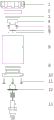
图1为本发明实施例一提出的一种水下照明设备的主视图;1 is a front view of an underwater lighting device proposed in
图2为本发明实施例一提出的一种水下照明设备的爆炸结构示意图;2 is a schematic diagram of an explosion structure of an underwater lighting device proposed in
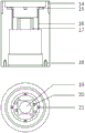
图3为本发明实施例一提出的一种水下照明设备部件-密封舱体结构示意图;3 is a schematic structural diagram of an underwater lighting equipment component-sealed cabin proposed in
图4为本发明实施例一提出的一种水下照明设备部件-后端盖结构示意图;4 is a schematic structural diagram of an underwater lighting equipment component-rear end cover proposed in
图5a为本发明实施例一提出的一种水下照明设备反光罩安装前结构示意图;5a is a schematic structural diagram of an underwater lighting equipment reflector before installation according to
图5b为本发明实施例一提出的一种水下照明设备反光罩安装后结构示意图;5b is a schematic structural diagram of an underwater lighting equipment reflector after installation according to
图6为本发明实施例一提出的一种水下照明设备第一水平环状支撑件,和第二水平环状支撑件示意图;6 is a schematic diagram of a first horizontal annular support member and a second horizontal annular support member of an underwater lighting device proposed in
图7为本发明实施例一提出的一种水下照明设备单体紫外灯珠作用范围示意图;7 is a schematic diagram of the action range of a single UV lamp bead of an underwater lighting device proposed in
图8a为本发明实施例一提出的一种水下照明设备单体紫外灯珠安装第一临界角度示意图;8a is a schematic diagram of a first critical angle for installing a single UV lamp bead of an underwater lighting device according to
图8b为本发明实施例一提出的一种水下照明设备单体紫外灯珠安装第二临界角度示意图;8b is a schematic diagram of a second critical angle for installing a single UV lamp bead of an underwater lighting device according to
图9为本发明实施例一提出的一种水下照明设备照明发光范围及紫外发光范围俯视图。FIG. 9 is a top view of the lighting luminous range and the ultraviolet luminous range of an underwater lighting device according to Embodiment 1 of the present invention.
具体实施方式Detailed ways
下面结合本发明实施例中的附图,对本发明实施例中的技术方案进行清楚、完整地描述,显然,所描述的实施例仅是本发明一部分实施例,而不是全部的实施例。基于本发明中的实施例,本领域普通技术人员在没有作出创造性劳动前提下所获得的所有其他实施例,都属于本发明保护范围。The technical solutions in the embodiments of the present invention will be clearly and completely described below with reference to the accompanying drawings in the embodiments of the present invention. Obviously, the described embodiments are only a part of the embodiments of the present invention, but not all of the embodiments. Based on the embodiments of the present invention, all other embodiments obtained by persons of ordinary skill in the art without creative efforts shall fall within the protection scope of the present invention.
实施例一Example 1
本实施例提供了一种水下照明设备,如图1-9所示。本实施例提供的包括锁紧盖1、透光罩2、轴向密封0型圈3、反光杯4、灯珠压紧螺栓5、与密封腔体侧壁一体连接的第一水平环状支撑件31,和第二水平环状支撑件32,灯珠6、紫外灯珠7、密封舱体8、径向密封O型圈9、后端盖10、后端盖锁紧螺栓11、恒流控制模组12、水密插座13。所述锁紧盖内部设有内螺纹;所述密封舱体上部外缘设有与锁紧盖配合的外螺纹14,内部设有密封槽15、紫外灯珠穿线孔16、灯珠穿线孔17、第一水平环状支撑件31上设置用于镶嵌灯珠的卡槽19、用于安装灯珠压紧螺栓的螺纹孔20、第二水平环状支撑件32上设置用于镶嵌紫外灯珠的紫外灯珠卡槽21、下部设有用于安装后端盖锁紧螺栓的螺纹孔18;所述后端盖设有密封槽22、供螺栓穿插的通孔23、便于拆卸矩形孔24、用于安装水密插座的螺纹孔25。金属密封舱体8与第一水平环状支撑件31,第二水平环状支撑件32,一体连接,有效将照明器件和紫外器件的热量传导至海水内,提高散热效率。This embodiment provides an underwater lighting device, as shown in Figures 1-9. This embodiment provides a
灯珠6放入密封舱体的卡槽19中,灯珠压紧螺栓5将其固定;紫外灯珠7放入卡槽21中,用特殊胶固定,轴向密封O型圈3置于密封舱体的密封槽15中,透光罩2卡入密封舱体上端并压在轴向密封O型圈3之上,锁紧盖1旋入密封舱体8并压紧透光罩2,密封舱体8的一端得以密封。水密插座13旋入后端盖螺纹孔25,旋紧即与后端盖10形成密封;水密插座后端与恒流模组一端插针相连,恒流模组的另一端与灯珠20、紫外灯珠卡槽21之间设置通孔,恒流模组通过贯穿通孔的电连接元件,如插针等,与灯珠6及紫外灯珠7相连,径向密封O型圈9放入后端盖密封槽22中,装有水密插座13及径向密封O型圈9的后端盖10插入密封舱体8中,后端盖锁紧螺栓11将其紧固,密封舱体8的另一端得以密封,解决水下LED照明灯防水问题。如图5a,5b所示,反光杯4卡接在第一水平环状支撑件31内,密封腔体侧壁限制所述反光杯4径向移动;通过透光罩2压紧反光杯4,限制所述反光杯4轴向移动。所述透光2罩材质为特殊石英玻璃,强度大、透光率高;所述锁紧盖1、所述密封舱体8、所述后端盖10材质为Hsn70-1,耐腐蚀、易加工,热传导率高。The
所述照明灯珠采用LED灯珠阵列,优选为高密度集成灯珠,亮度高、独立性强,单珠损坏不影响其它灯珠照明。所述紫外灯珠优选为单体灯珠,体积较小,照射辐射角优选为70°,有效作用半径100mm,能够发射特定范围波长紫外线,以破坏海洋生物体内DNA或RNA的分子结构,达到防生物污染的效果。The lighting lamp bead adopts an LED lamp bead array, preferably a high-density integrated lamp bead, with high brightness and strong independence, and the damage of a single bead does not affect the lighting of other lamp beads. The ultraviolet lamp bead is preferably a single lamp bead, with a small volume, an irradiation radiation angle of preferably 70°, an effective radius of 100mm, and can emit ultraviolet rays of a specific range of wavelengths to destroy the molecular structure of DNA or RNA in marine organisms, and achieve anti-aging. effects of biological contamination.
所述密封舱体与所述照明灯珠紧密贴合,所述密封舱体作为所述照明灯珠的基座,不仅起到密封防护作用,还起到传热降温效果,直接将所述灯珠产生的热量传至水中,解决了所述灯珠长时间工作散热问题。The sealed cabin body is closely attached to the lighting lamp beads, and the sealed cabin body serves as the base of the lighting lamp beads, which not only plays a role of sealing and protection, but also has a heat transfer and cooling effect, and directly connects the lamp to the lamp. The heat generated by the beads is transferred to the water, which solves the problem of heat dissipation during long-term operation of the lamp beads.
为了保障透明罩防生物附着效果,同时为了减少不必要的能源损耗,本实施例对紫外灯珠的数量、单体紫外灯珠安装角度进行了分析处理,使其组合最优化,如图7-9所示。In order to ensure the anti-biological adhesion effect of the transparent cover, and at the same time to reduce unnecessary energy consumption, in this embodiment, the number of UV lamp beads and the installation angle of a single UV lamp bead are analyzed and processed to optimize the combination, as shown in Figure 7- 9 shown.
由于照明灯珠发热较大,为了减少高温对透光罩的影响,因此使照明灯珠6与透光罩2保持了一定的距离。因单体紫外灯珠发热量相对较小,可忽略其对透光罩的影响,同时为了减少水下照明灯其他部件对紫外光的遮挡,紫外灯珠被布置在靠近透光罩的位置。Since the lighting lamp beads generate relatively large heat, in order to reduce the influence of high temperature on the light-transmitting cover, the
紫外灯珠布置在照明灯珠的外围,因此紫外灯珠安装时应该向照明灯珠方向倾斜,以使更多紫外光穿过透光罩起到保护作用。经数据计算及建模分析,一个紫外灯珠不能满足紫外光全覆盖保护面,因此采用多灯珠分布组合方式。本实施例在放置紫外灯珠7的紫外灯珠卡槽21内部,靠近密封舱体内部一侧或多侧设置高度调节元件33,高度调节元件33可以是通过旋转调整高度的螺丝类元件,或通过按压可设置弹起或落下的垫片。高度调节元件包括多个连续或间断的档位,通过调整高度调节元件的高度档位,控制加工紫外灯珠卡槽底面与水平面的夹角,进而控制紫外灯珠倾斜角度。紫外灯珠7的倾斜地放置在紫外灯珠卡槽21内,通过调整高度调整单元的高度档位,适应需要不同照明范围需求的设备。每颗紫外灯珠连有两根引线,紫外灯珠与两根引线通过焊锡焊接,引线另一端与电路板通过插针相连。The UV lamp beads are arranged on the periphery of the lighting lamp bead, so the UV lamp bead should be tilted towards the lighting lamp bead when installed, so that more ultraviolet light can pass through the light-transmitting cover for protection. After data calculation and modeling analysis, one UV lamp bead can not meet the full coverage of UV light, so the distribution and combination of multiple lamp beads is adopted. In this embodiment, a
通过选取紫外灯珠与照明灯珠的截面分析,为使单体紫外光源能够穿过透光罩上部中心点以及单体紫外光源能够照到锁紧盖内孔边缘,计算出紫外灯珠安装适宜角度为19°-24°,临界角度时的紫外光源发光范围如图8a-8b所示。在安装角度为19°时,紫外灯珠右侧光源刚好穿过透光罩中心;在安装角度为24°时,紫外灯珠左侧光源刚好照到锁紧盖内孔边缘。By selecting the cross-section analysis of the UV lamp beads and the lighting lamp beads, in order to enable the single UV light source to pass through the upper center point of the light-transmitting cover and the single UV light source to illuminate the edge of the inner hole of the locking cover, it is calculated that the installation of the UV lamp beads is suitable. The angle is 19°-24°, and the luminous range of the UV light source at the critical angle is shown in Figures 8a-8b. When the installation angle is 19°, the light source on the right side of the UV lamp bead just passes through the center of the light-transmitting cover; when the installation angle is 24°, the light source on the left side of the UV lamp bead just shines on the edge of the inner hole of the locking cover.
通过选取透光罩上表面所在截面分析,为使单体紫外光源之间相互补充又不冗余,经建模分析,最终确定紫外灯珠数量至少为5,圆周均布排列,照明发光范围及紫外发光范围如图9所示。By selecting the cross-section of the upper surface of the light-transmitting cover, in order to make the individual UV light sources complement each other without redundancy, after modeling and analysis, it is finally determined that the number of UV lamp beads is at least 5, the circumference is evenly distributed, the lighting range and The UV emission range is shown in Figure 9.
本实施例提供的技术方案,通过紫外发光单元与照明发光单元的配合,一体化实现耐压、耐腐蚀,结构构造简单、实用,方便装配、易于维修。通过设置可调整紫外发光单元的倾斜角度,获得多个有效紫外发光范围,可广泛应用于多种照明范围需求的水下照明设备,无论是单独使用还是用于搭载到其他设备上,都提高了用户使用的便利性。通过涉及一体化的金属密封腔体-金属照明单元支撑件-金属紫外单元支撑件,有效将照明器件和紫外器件的热量传导至海水内,提高散热效率。The technical solution provided by this embodiment, through the cooperation of the ultraviolet light-emitting unit and the lighting light-emitting unit, realizes the pressure resistance and corrosion resistance in an integrated manner, the structure is simple and practical, and the assembly and maintenance are convenient. By setting the inclination angle of the adjustable ultraviolet light-emitting unit, multiple effective ultraviolet light-emitting ranges can be obtained, which can be widely used in underwater lighting equipment with various lighting range requirements. User convenience. By involving an integrated metal sealing cavity-metal lighting unit support-metal ultraviolet unit support, the heat of the lighting device and the ultraviolet device is effectively conducted into the seawater, and the heat dissipation efficiency is improved.
以上所述的具体实施例,对本发明的目的,技术方案和有益效果进行了进一步详细说明,所应理解的是,以上所述仅为本发明的具体实施例,并不用于限定本发明的保护范围,凡在本发明的精神和原则之内,所做的任何修改、等同替换、改进等,均应包含在本发明的保护范围之内。The specific embodiments described above further describe the purpose, technical solutions and beneficial effects of the present invention in detail. It should be understood that the above-mentioned specific embodiments are only specific embodiments of the present invention, and are not intended to limit the protection of the present invention. Any modification, equivalent replacement, improvement, etc. made within the spirit and principle of the present invention shall be included within the protection scope of the present invention.
Claims (10)
Priority Applications (1)
| Application Number | Priority Date | Filing Date | Title |
|---|---|---|---|
| CN202010173813.6A CN111237683B (en) | 2020-03-13 | 2020-03-13 | an underwater lighting device |
Applications Claiming Priority (1)
| Application Number | Priority Date | Filing Date | Title |
|---|---|---|---|
| CN202010173813.6A CN111237683B (en) | 2020-03-13 | 2020-03-13 | an underwater lighting device |
Publications (2)
| Publication Number | Publication Date |
|---|---|
| CN111237683A true CN111237683A (en) | 2020-06-05 |
| CN111237683B CN111237683B (en) | 2022-05-17 |
Family
ID=70867421
Family Applications (1)
| Application Number | Title | Priority Date | Filing Date |
|---|---|---|---|
| CN202010173813.6A Active CN111237683B (en) | 2020-03-13 | 2020-03-13 | an underwater lighting device |
Country Status (1)
| Country | Link |
|---|---|
| CN (1) | CN111237683B (en) |
Citations (11)
| Publication number | Priority date | Publication date | Assignee | Title |
|---|---|---|---|---|
| CN2550636Y (en) * | 2002-06-07 | 2003-05-14 | 中国科学院沈阳自动化研究所 | Underwater lighting lamp |
| CN201866628U (en) * | 2010-10-21 | 2011-06-15 | 邓亦林 | Spotlight with adjustable beam angle |
| CN202001894U (en) * | 2011-01-20 | 2011-10-05 | 宜兴爱特盟光电科技有限公司 | Light-emitting diode (LED) lamp for optical detection device |
| CN102639927A (en) * | 2009-12-02 | 2012-08-15 | 欧司朗股份有限公司 | Lighting apparatus for a beacon system |
| CN103867969A (en) * | 2012-12-14 | 2014-06-18 | 罗斯蒙特航天公司 | Surveillance device |
| CN105402611A (en) * | 2015-12-15 | 2016-03-16 | 太龙(福建)商业照明股份有限公司 | An LED anti-glare ring depth adjustment device |
| CN206958719U (en) * | 2017-05-17 | 2018-02-02 | 孙利嫚 | A kind of underwater LED lamp cylinder with sterilizing function |
| CN207034729U (en) * | 2017-07-31 | 2018-02-23 | 广东凯西欧照明有限公司 | A kind of infrared illumination device |
| CN208719995U (en) * | 2018-09-26 | 2019-04-09 | 深圳市奋华自动化科技有限公司 | A kind of anti-interference vision light source |
| CN209137771U (en) * | 2018-03-21 | 2019-07-23 | 厦门通秴科技股份有限公司 | Human body recovery health therapy headlamp and system |
| CN209341214U (en) * | 2019-01-29 | 2019-09-03 | 泉州德化县嘉欧利工艺品有限责任公司 | A kind of ceramic lamp with monitoring function |
-
2020
- 2020-03-13 CN CN202010173813.6A patent/CN111237683B/en active Active
Patent Citations (11)
| Publication number | Priority date | Publication date | Assignee | Title |
|---|---|---|---|---|
| CN2550636Y (en) * | 2002-06-07 | 2003-05-14 | 中国科学院沈阳自动化研究所 | Underwater lighting lamp |
| CN102639927A (en) * | 2009-12-02 | 2012-08-15 | 欧司朗股份有限公司 | Lighting apparatus for a beacon system |
| CN201866628U (en) * | 2010-10-21 | 2011-06-15 | 邓亦林 | Spotlight with adjustable beam angle |
| CN202001894U (en) * | 2011-01-20 | 2011-10-05 | 宜兴爱特盟光电科技有限公司 | Light-emitting diode (LED) lamp for optical detection device |
| CN103867969A (en) * | 2012-12-14 | 2014-06-18 | 罗斯蒙特航天公司 | Surveillance device |
| CN105402611A (en) * | 2015-12-15 | 2016-03-16 | 太龙(福建)商业照明股份有限公司 | An LED anti-glare ring depth adjustment device |
| CN206958719U (en) * | 2017-05-17 | 2018-02-02 | 孙利嫚 | A kind of underwater LED lamp cylinder with sterilizing function |
| CN207034729U (en) * | 2017-07-31 | 2018-02-23 | 广东凯西欧照明有限公司 | A kind of infrared illumination device |
| CN209137771U (en) * | 2018-03-21 | 2019-07-23 | 厦门通秴科技股份有限公司 | Human body recovery health therapy headlamp and system |
| CN208719995U (en) * | 2018-09-26 | 2019-04-09 | 深圳市奋华自动化科技有限公司 | A kind of anti-interference vision light source |
| CN209341214U (en) * | 2019-01-29 | 2019-09-03 | 泉州德化县嘉欧利工艺品有限责任公司 | A kind of ceramic lamp with monitoring function |
Also Published As
| Publication number | Publication date |
|---|---|
| CN111237683B (en) | 2022-05-17 |
Similar Documents
| Publication | Publication Date | Title |
|---|---|---|
| CA2497545C (en) | Compact light emitting diode retrofit lamp and method for traffic signal lights | |
| US7488097B2 (en) | LED lamp module | |
| US7396139B2 (en) | Underwater lighting apparatus | |
| CN101963293B (en) | Light emitting diode lamp | |
| US9371966B2 (en) | Lighting fixture | |
| US8376577B2 (en) | Modular solid state lighting device | |
| US7520628B1 (en) | High flux led lamp | |
| CN101929625A (en) | Light emitting diode (LED) lamp | |
| JP2011503786A5 (en) | ||
| CN101839413A (en) | LED fluorescent lamp | |
| CN102575817A (en) | Lamp | |
| CN101446392A (en) | LED light source module | |
| CN102128367A (en) | Light-emitting diode lamp | |
| JP2011014515A (en) | Lighting fixture excellent on illuminance and light-distribution nature | |
| CN102052589A (en) | Light-emitting diode lamp | |
| CN111237683A (en) | an underwater lighting device | |
| CN201259195Y (en) | LED projection lamp | |
| CN202452238U (en) | LED (Light Emitting Diode) lamp | |
| JP7365639B2 (en) | lighting equipment | |
| CN211399527U (en) | Embedded dual-purpose lamp for ramp indication | |
| CN210319453U (en) | Point light source | |
| CN201354956Y (en) | Led light source module | |
| CN223360594U (en) | A high-brightness light source for deep sea use | |
| CN219140532U (en) | Light underwater laser lamp | |
| CN210197035U (en) | LED corn lamp |
Legal Events
| Date | Code | Title | Description |
|---|---|---|---|
| PB01 | Publication | ||
| PB01 | Publication | ||
| SE01 | Entry into force of request for substantive examination | ||
| SE01 | Entry into force of request for substantive examination | ||
| TA01 | Transfer of patent application right |
Effective date of registration: 20220422 Address after: 572024 area C310, third floor, phase II standard plant, yazhouwan science and Technology City, Yazhou District, Sanya City, Hainan Province Applicant after: Research Institute of Hainan Zhejiang University Address before: 316021 No.1, Zheda Road, Dinghai District, Zhoushan City, Zhejiang Province Applicant before: ZHEJIANG University |
|
| TA01 | Transfer of patent application right | ||
| GR01 | Patent grant | ||
| GR01 | Patent grant |