CN111237700A - A kind of multifunctional wind power circuit lamp - Google Patents
A kind of multifunctional wind power circuit lamp Download PDFInfo
- Publication number
- CN111237700A CN111237700A CN202010177090.7A CN202010177090A CN111237700A CN 111237700 A CN111237700 A CN 111237700A CN 202010177090 A CN202010177090 A CN 202010177090A CN 111237700 A CN111237700 A CN 111237700A
- Authority
- CN
- China
- Prior art keywords
- fixed
- power
- cavity
- housing
- rotating shaft
- Prior art date
- Legal status (The legal status is an assumption and is not a legal conclusion. Google has not performed a legal analysis and makes no representation as to the accuracy of the status listed.)
- Granted
Links
Images



Classifications
-
- F—MECHANICAL ENGINEERING; LIGHTING; HEATING; WEAPONS; BLASTING
- F21—LIGHTING
- F21S—NON-PORTABLE LIGHTING DEVICES; SYSTEMS THEREOF; VEHICLE LIGHTING DEVICES SPECIALLY ADAPTED FOR VEHICLE EXTERIORS
- F21S9/00—Lighting devices with a built-in power supply; Systems employing lighting devices with a built-in power supply
- F21S9/02—Lighting devices with a built-in power supply; Systems employing lighting devices with a built-in power supply the power supply being a battery or accumulator
- F21S9/026—Lighting devices with a built-in power supply; Systems employing lighting devices with a built-in power supply the power supply being a battery or accumulator rechargeable by using wind power, e.g. using wind turbines
-
- F—MECHANICAL ENGINEERING; LIGHTING; HEATING; WEAPONS; BLASTING
- F03—MACHINES OR ENGINES FOR LIQUIDS; WIND, SPRING, OR WEIGHT MOTORS; PRODUCING MECHANICAL POWER OR A REACTIVE PROPULSIVE THRUST, NOT OTHERWISE PROVIDED FOR
- F03D—WIND MOTORS
- F03D7/00—Controlling wind motors
- F03D7/02—Controlling wind motors the wind motors having rotation axis substantially parallel to the air flow entering the rotor
- F03D7/0204—Controlling wind motors the wind motors having rotation axis substantially parallel to the air flow entering the rotor for orientation in relation to wind direction
-
- F—MECHANICAL ENGINEERING; LIGHTING; HEATING; WEAPONS; BLASTING
- F03—MACHINES OR ENGINES FOR LIQUIDS; WIND, SPRING, OR WEIGHT MOTORS; PRODUCING MECHANICAL POWER OR A REACTIVE PROPULSIVE THRUST, NOT OTHERWISE PROVIDED FOR
- F03D—WIND MOTORS
- F03D7/00—Controlling wind motors
- F03D7/02—Controlling wind motors the wind motors having rotation axis substantially parallel to the air flow entering the rotor
- F03D7/04—Automatic control; Regulation
-
- F—MECHANICAL ENGINEERING; LIGHTING; HEATING; WEAPONS; BLASTING
- F03—MACHINES OR ENGINES FOR LIQUIDS; WIND, SPRING, OR WEIGHT MOTORS; PRODUCING MECHANICAL POWER OR A REACTIVE PROPULSIVE THRUST, NOT OTHERWISE PROVIDED FOR
- F03D—WIND MOTORS
- F03D9/00—Adaptations of wind motors for special use; Combinations of wind motors with apparatus driven thereby; Wind motors specially adapted for installation in particular locations
- F03D9/10—Combinations of wind motors with apparatus storing energy
- F03D9/11—Combinations of wind motors with apparatus storing energy storing electrical energy
-
- F—MECHANICAL ENGINEERING; LIGHTING; HEATING; WEAPONS; BLASTING
- F03—MACHINES OR ENGINES FOR LIQUIDS; WIND, SPRING, OR WEIGHT MOTORS; PRODUCING MECHANICAL POWER OR A REACTIVE PROPULSIVE THRUST, NOT OTHERWISE PROVIDED FOR
- F03D—WIND MOTORS
- F03D9/00—Adaptations of wind motors for special use; Combinations of wind motors with apparatus driven thereby; Wind motors specially adapted for installation in particular locations
- F03D9/30—Wind motors specially adapted for installation in particular locations
- F03D9/34—Wind motors specially adapted for installation in particular locations on stationary objects or on stationary man-made structures
- F03D9/43—Wind motors specially adapted for installation in particular locations on stationary objects or on stationary man-made structures using infrastructure primarily used for other purposes, e.g. masts for overhead railway power lines
-
- F—MECHANICAL ENGINEERING; LIGHTING; HEATING; WEAPONS; BLASTING
- F21—LIGHTING
- F21S—NON-PORTABLE LIGHTING DEVICES; SYSTEMS THEREOF; VEHICLE LIGHTING DEVICES SPECIALLY ADAPTED FOR VEHICLE EXTERIORS
- F21S8/00—Lighting devices intended for fixed installation
- F21S8/08—Lighting devices intended for fixed installation with a standard
- F21S8/085—Lighting devices intended for fixed installation with a standard of high-built type, e.g. street light
- F21S8/086—Lighting devices intended for fixed installation with a standard of high-built type, e.g. street light with lighting device attached sideways of the standard, e.g. for roads and highways
-
- F—MECHANICAL ENGINEERING; LIGHTING; HEATING; WEAPONS; BLASTING
- F21—LIGHTING
- F21S—NON-PORTABLE LIGHTING DEVICES; SYSTEMS THEREOF; VEHICLE LIGHTING DEVICES SPECIALLY ADAPTED FOR VEHICLE EXTERIORS
- F21S9/00—Lighting devices with a built-in power supply; Systems employing lighting devices with a built-in power supply
- F21S9/04—Lighting devices with a built-in power supply; Systems employing lighting devices with a built-in power supply the power supply being a generator
- F21S9/043—Lighting devices with a built-in power supply; Systems employing lighting devices with a built-in power supply the power supply being a generator driven by wind power, e.g. by wind turbines
-
- F—MECHANICAL ENGINEERING; LIGHTING; HEATING; WEAPONS; BLASTING
- F21—LIGHTING
- F21V—FUNCTIONAL FEATURES OR DETAILS OF LIGHTING DEVICES OR SYSTEMS THEREOF; STRUCTURAL COMBINATIONS OF LIGHTING DEVICES WITH OTHER ARTICLES, NOT OTHERWISE PROVIDED FOR
- F21V23/00—Arrangement of electric circuit elements in or on lighting devices
- F21V23/003—Arrangement of electric circuit elements in or on lighting devices the elements being electronics drivers or controllers for operating the light source, e.g. for a LED array
-
- F—MECHANICAL ENGINEERING; LIGHTING; HEATING; WEAPONS; BLASTING
- F21—LIGHTING
- F21V—FUNCTIONAL FEATURES OR DETAILS OF LIGHTING DEVICES OR SYSTEMS THEREOF; STRUCTURAL COMBINATIONS OF LIGHTING DEVICES WITH OTHER ARTICLES, NOT OTHERWISE PROVIDED FOR
- F21V23/00—Arrangement of electric circuit elements in or on lighting devices
- F21V23/02—Arrangement of electric circuit elements in or on lighting devices the elements being transformers, impedances or power supply units, e.g. a transformer with a rectifier
-
- F—MECHANICAL ENGINEERING; LIGHTING; HEATING; WEAPONS; BLASTING
- F21—LIGHTING
- F21W—INDEXING SCHEME ASSOCIATED WITH SUBCLASSES F21K, F21L, F21S and F21V, RELATING TO USES OR APPLICATIONS OF LIGHTING DEVICES OR SYSTEMS
- F21W2131/00—Use or application of lighting devices or systems not provided for in codes F21W2102/00-F21W2121/00
- F21W2131/10—Outdoor lighting
- F21W2131/103—Outdoor lighting of streets or roads
-
- Y—GENERAL TAGGING OF NEW TECHNOLOGICAL DEVELOPMENTS; GENERAL TAGGING OF CROSS-SECTIONAL TECHNOLOGIES SPANNING OVER SEVERAL SECTIONS OF THE IPC; TECHNICAL SUBJECTS COVERED BY FORMER USPC CROSS-REFERENCE ART COLLECTIONS [XRACs] AND DIGESTS
- Y02—TECHNOLOGIES OR APPLICATIONS FOR MITIGATION OR ADAPTATION AGAINST CLIMATE CHANGE
- Y02B—CLIMATE CHANGE MITIGATION TECHNOLOGIES RELATED TO BUILDINGS, e.g. HOUSING, HOUSE APPLIANCES OR RELATED END-USER APPLICATIONS
- Y02B10/00—Integration of renewable energy sources in buildings
- Y02B10/30—Wind power
-
- Y—GENERAL TAGGING OF NEW TECHNOLOGICAL DEVELOPMENTS; GENERAL TAGGING OF CROSS-SECTIONAL TECHNOLOGIES SPANNING OVER SEVERAL SECTIONS OF THE IPC; TECHNICAL SUBJECTS COVERED BY FORMER USPC CROSS-REFERENCE ART COLLECTIONS [XRACs] AND DIGESTS
- Y02—TECHNOLOGIES OR APPLICATIONS FOR MITIGATION OR ADAPTATION AGAINST CLIMATE CHANGE
- Y02B—CLIMATE CHANGE MITIGATION TECHNOLOGIES RELATED TO BUILDINGS, e.g. HOUSING, HOUSE APPLIANCES OR RELATED END-USER APPLICATIONS
- Y02B20/00—Energy efficient lighting technologies, e.g. halogen lamps or gas discharge lamps
- Y02B20/72—Energy efficient lighting technologies, e.g. halogen lamps or gas discharge lamps in street lighting
-
- Y—GENERAL TAGGING OF NEW TECHNOLOGICAL DEVELOPMENTS; GENERAL TAGGING OF CROSS-SECTIONAL TECHNOLOGIES SPANNING OVER SEVERAL SECTIONS OF THE IPC; TECHNICAL SUBJECTS COVERED BY FORMER USPC CROSS-REFERENCE ART COLLECTIONS [XRACs] AND DIGESTS
- Y02—TECHNOLOGIES OR APPLICATIONS FOR MITIGATION OR ADAPTATION AGAINST CLIMATE CHANGE
- Y02E—REDUCTION OF GREENHOUSE GAS [GHG] EMISSIONS, RELATED TO ENERGY GENERATION, TRANSMISSION OR DISTRIBUTION
- Y02E10/00—Energy generation through renewable energy sources
- Y02E10/70—Wind energy
- Y02E10/72—Wind turbines with rotation axis in wind direction
-
- Y—GENERAL TAGGING OF NEW TECHNOLOGICAL DEVELOPMENTS; GENERAL TAGGING OF CROSS-SECTIONAL TECHNOLOGIES SPANNING OVER SEVERAL SECTIONS OF THE IPC; TECHNICAL SUBJECTS COVERED BY FORMER USPC CROSS-REFERENCE ART COLLECTIONS [XRACs] AND DIGESTS
- Y02—TECHNOLOGIES OR APPLICATIONS FOR MITIGATION OR ADAPTATION AGAINST CLIMATE CHANGE
- Y02E—REDUCTION OF GREENHOUSE GAS [GHG] EMISSIONS, RELATED TO ENERGY GENERATION, TRANSMISSION OR DISTRIBUTION
- Y02E10/00—Energy generation through renewable energy sources
- Y02E10/70—Wind energy
- Y02E10/728—Onshore wind turbines
-
- Y—GENERAL TAGGING OF NEW TECHNOLOGICAL DEVELOPMENTS; GENERAL TAGGING OF CROSS-SECTIONAL TECHNOLOGIES SPANNING OVER SEVERAL SECTIONS OF THE IPC; TECHNICAL SUBJECTS COVERED BY FORMER USPC CROSS-REFERENCE ART COLLECTIONS [XRACs] AND DIGESTS
- Y02—TECHNOLOGIES OR APPLICATIONS FOR MITIGATION OR ADAPTATION AGAINST CLIMATE CHANGE
- Y02E—REDUCTION OF GREENHOUSE GAS [GHG] EMISSIONS, RELATED TO ENERGY GENERATION, TRANSMISSION OR DISTRIBUTION
- Y02E70/00—Other energy conversion or management systems reducing GHG emissions
- Y02E70/30—Systems combining energy storage with energy generation of non-fossil origin
Landscapes
- Engineering & Computer Science (AREA)
- General Engineering & Computer Science (AREA)
- Life Sciences & Earth Sciences (AREA)
- Sustainable Development (AREA)
- Sustainable Energy (AREA)
- Chemical & Material Sciences (AREA)
- Combustion & Propulsion (AREA)
- Mechanical Engineering (AREA)
- Power Engineering (AREA)
- Microelectronics & Electronic Packaging (AREA)
- Wind Motors (AREA)
- Non-Portable Lighting Devices Or Systems Thereof (AREA)
Abstract
本发明装置的一种多功能风力发电路灯,包括动力壳体和位于所述动力壳体内的动力装置,所述动力装置包括转向动力腔,所述转向动力腔的下端壁固设有储电池,所述储电池的上端面固设有转向电机,所述动力壳体的左端面固设有路灯壳体,所述动力装置的上侧设有发电装置,所述发电装置包括转动壳体,所述转动壳体内设有转换腔以及位于所述转换腔左侧的发电腔,本装置能够自动识别风的方向,自动将扇叶对准风的方向,实现了不用人为操作而使风力的利用率最大化,同时可自动判别电量的多少,进而控制晚上照明所用灯泡的数量,避免因发电量较低的情况下而无法延长照明时间的问题,同时解决了发电量过大造成过冲的问题。

A multifunctional wind power generating circuit lamp of the device of the present invention comprises a power housing and a power device located in the power housing, the power device comprises a steering power cavity, and a storage battery is fixed on the lower end wall of the steering power cavity, A steering motor is fixed on the upper end face of the storage battery, a street lamp casing is fixed on the left end face of the power housing, and a power generating device is arranged on the upper side of the power device, and the power generating device includes a rotating housing, so The rotating casing is provided with a conversion cavity and a power generation cavity located on the left side of the conversion cavity. The device can automatically identify the direction of the wind and automatically align the fan blades with the direction of the wind, so as to realize the utilization rate of wind power without manual operation. At the same time, it can automatically determine the amount of electricity, and then control the number of bulbs used for lighting at night, avoiding the problem that the lighting time cannot be extended due to low power generation, and solving the problem of overshoot caused by excessive power generation.
Description
技术领域technical field
本发明涉及风能技术领域,具体地说是一种多功能风力发电路灯。The invention relates to the technical field of wind energy, in particular to a multifunctional wind power generating circuit lamp.
背景技术Background technique
风力发电路灯是一种利用风能作为能源的路灯,因其具有不受供电影响,不用开沟埋线,不消耗常规电能,只要风力充足就可以就地安装等特点,因此受到人们的广泛关注,又因其不污染环境,而被称为绿色环保产品,风力发电路灯适用于沿海地带公园、道路、草坪的照明,又可用于人口分布密度较小,交通不便经济不发达、缺乏常规燃料,难以用常规能源发电,但是常规的风力发电只能朝向一个方向,无法辨别风的来向,而造成发电不及时,或是发的电不够晚上照明所用。Wind-powered circuit light is a street light that uses wind energy as energy. Because it is not affected by power supply, does not need to dig trenches and bury wires, does not consume conventional electricity, and can be installed on-site as long as there is sufficient wind power, it has received widespread attention. It is also known as a green product because it does not pollute the environment. Wind-powered circuit lights are suitable for lighting in parks, roads, and lawns in coastal areas. Conventional energy is used to generate electricity, but conventional wind power can only be directed in one direction, and it is impossible to distinguish the direction of the wind, resulting in untimely power generation, or insufficient power for night lighting.
发明内容SUMMARY OF THE INVENTION
针对上述技术的不足,本发明提出了一种多功能风力发电路灯,能够克服上述缺陷。In view of the deficiencies of the above-mentioned technologies, the present invention proposes a multifunctional wind-powered circuit lamp, which can overcome the above-mentioned deficiencies.
本发明装置的一种多功能风力发电路灯,包括动力壳体和位于所述动力壳体内的动力装置,所述动力装置包括转向动力腔,所述转向动力腔的下端壁固设有储电池,所述储电池的上端面固设有转向电机,所述动力壳体的左端面固设有路灯壳体,所述动力装置的上侧设有发电装置,所述发电装置包括转动壳体,所述转动壳体内设有转换腔以及位于所述转换腔左侧的发电腔,所述发电腔的上端壁靠近左侧位置固设有固定壳体,所述固定壳体内设有凸轮槽,所述发电腔的下端壁固设有发电机,所述路灯壳体内设有照明装置,所述照明装置包括电磁腔和位于所述电磁腔下侧的路灯槽,且所述路灯槽开口向下,所述动力壳体的上端面固设有两个左右对称设置的固定轴,所述转动壳体的下端面设有位于两个所述固定轴上侧且开口向下的两个T型滑槽,所述固定轴的上端面固设有与所述T型滑槽滑动连接的滑块,所述凸轮槽的前后左右端壁均设有固定弹簧,所述内固设有插座槽以及位于所述插座槽内侧的插头,所述插头和所述插座槽之间固定连接有插座。A multifunctional wind power generating circuit lamp of the device of the present invention comprises a power housing and a power device located in the power housing, the power device comprises a steering power cavity, and a storage battery is fixed on the lower end wall of the steering power cavity, A steering motor is fixed on the upper end face of the storage battery, a street lamp casing is fixed on the left end face of the power casing, and a power generation device is arranged on the upper side of the power device, and the power generation device includes a rotating casing, so The rotating casing is provided with a conversion cavity and a power generation cavity on the left side of the conversion cavity, a fixed casing is fixed on the upper end wall of the power generation cavity near the left side, and a cam groove is arranged in the fixed casing. A generator is fixed on the lower end wall of the power generation cavity, and a lighting device is arranged in the street lamp housing. The lighting device includes an electromagnetic cavity and a street lamp slot located on the lower side of the electromagnetic cavity, and the street lamp slot opens downward, so The upper end surface of the power housing is fixed with two left-right symmetrical fixed shafts, and the lower end surface of the rotating housing is provided with two T-shaped sliding grooves located on the upper sides of the two fixed shafts and opening downwards, The upper end surface of the fixed shaft is fixedly provided with a sliding block slidably connected to the T-shaped chute, the front, rear, left and right end walls of the cam groove are provided with fixed springs, and a socket groove is fixed inside the A plug inside the socket slot, a socket is fixedly connected between the plug and the socket slot.
优选地,所述转向电机的上侧动力连接有向上延伸且与所述动力壳体转动连接的第一转动轴,所述第一转动轴的顶部末端固与所述转动壳体的下端面固定连接,所述储电池固定连接有第一导线的一端。Preferably, the upper side of the steering motor is powered with a first rotating shaft that extends upward and is rotatably connected to the power housing, and the top end of the first rotating shaft is fixed to the lower end surface of the rotating housing. connected, the storage battery is fixedly connected with one end of the first wire.
优选地,所述路灯槽内设有三个第一灯泡组以及位于所述第一灯泡组右侧的三个第二灯泡组,所述第一灯泡组通过第二导线串联,所述电磁腔的左端壁固设有电铁开关,所述电铁开关的右侧设有与所述电磁腔滑动连接的左导电板,所述左导电板的右侧设有与所述电磁腔固定连接的右导电板,所述电铁开关和所述左导电板之间固定连接有电磁弹簧,所述第二导线的另一端与所述左导电板的左端面固定连接,所述第二灯泡组通过所述转向动力腔串联,所述第一导线的另一端固定连接于所述右导电板的右端面。Preferably, three first light bulb groups and three second light bulb groups located on the right side of the first light bulb group are arranged in the street light trough, the first light bulb groups are connected in series by second wires, and the electromagnetic cavity is connected in series. The left end wall is fixed with an electric iron switch, the right side of the electric iron switch is provided with a left conductive plate that is slidably connected to the electromagnetic cavity, and the right side of the left conductive plate is provided with a right conductive plate that is fixedly connected to the electromagnetic cavity. A conductive plate, an electromagnetic spring is fixedly connected between the electric iron switch and the left conductive plate, the other end of the second wire is fixedly connected to the left end face of the left conductive plate, and the second bulb group passes through the The steering power chambers are connected in series, and the other end of the first wire is fixedly connected to the right end surface of the right conductive plate.
优选地,所述转换腔内转动连接有向右延伸的第二转动轴,所述第二转动轴的右侧末端固定连接有位于所述转动壳体右端面右侧的扇叶固定套,所述扇叶固定套上固设有三个均匀分布的扇叶,所述第二转动轴的左侧花键连接有花键套,所述花键套转动连接于滑板上,所述滑板的右端面与电磁开关固定连接,所述电磁开关与所述转换腔的右端壁固定连接。Preferably, a second rotating shaft extending to the right is rotatably connected in the conversion cavity, and a fan blade fixing sleeve located on the right side of the right end face of the rotating housing is fixedly connected to the right end of the second rotating shaft, so The fan blade fixing sleeve is fixed with three evenly distributed fan blades, the left side of the second rotating shaft is connected with a spline sleeve, the spline sleeve is rotatably connected to the sliding plate, and the right end surface of the sliding plate is connected to the sliding plate. It is fixedly connected with the electromagnetic switch, and the electromagnetic switch is fixedly connected with the right end wall of the conversion cavity.
优选地,所述花键套的左侧花键连接有向左延伸且与所述转动壳体转动连接的第三转动轴,所述第三转动轴的左侧末端固设有位于所述发电腔内的第一锥齿轮,所述发电机的上侧动力连接有电量检测器,所述电量检测器上固设有固定标识以及位于所述固定标识上侧的第二锥齿轮,且所述第二锥齿轮与所述第一锥齿轮啮合连接,所述发电腔的左端壁固设有位于所述固定标识左侧的电量检测器。Preferably, the left spline of the spline sleeve is connected with a third rotating shaft extending leftward and rotatably connected with the rotating housing, and the left end of the third rotating shaft is fixed with a The first bevel gear in the cavity, the upper side of the generator is powered with a power detector, the power detector is fixed with a fixed mark and a second bevel gear located on the upper side of the fixed mark, and the power detector is The second bevel gear is in meshing connection with the first bevel gear, and a power detector located on the left side of the fixed mark is fixed on the left end wall of the power generation chamber.
优选地,所述凸轮槽内设有向上延伸且与所述转动壳体转动连接的第四转动轴,所述第四转动轴的顶部末端固设有位于所述转动壳体上端面上侧的风向标,所述第四转动轴的底部末端固设有位于所述凸轮槽内的凸轮,且所述凸轮位于四个个所述固定弹簧之间。Preferably, a fourth rotating shaft extending upward and rotatably connected to the rotating casing is arranged in the cam groove, and a top end of the fourth rotating shaft is fixed with a rotating shaft located on the upper side of the upper end surface of the rotating casing. In the wind vane, a cam located in the cam groove is fixed at the bottom end of the fourth rotating shaft, and the cam is located between the four fixed springs.
有益效果为:本装置能够自动识别风的方向,自动将扇叶对准风的方向,实现了不用人为操作而使风力的利用率最大化,同时可自动判别电量的多少,进而控制晚上照明所用灯泡的数量,避免因发电量较低的情况下而无法延长照明时间的问题,同时解决了发电量过大造成过冲的问题。The beneficial effects are as follows: the device can automatically identify the direction of the wind, automatically align the fan blades with the direction of the wind, maximize the utilization rate of the wind power without manual operation, and at the same time can automatically determine the amount of electricity, so as to control the use of night lighting. The number of bulbs avoids the problem that the lighting time cannot be extended due to low power generation, and at the same time solves the problem of overshoot caused by excessive power generation.
附图说明Description of drawings
为了更清楚地说明发明实施例或现有技术中的技术方案,下面将对实施例或现有技术描述中所需要使用的附图作简单地介绍,显而易见地,下面描述中的附图仅仅是发明的一些实施例,对于本领域普通技术人员来讲,在不付出创造性劳动的前提下,还可以根据这些附图获得其他的附图。In order to illustrate the embodiments of the invention or the technical solutions in the prior art more clearly, the following briefly introduces the accompanying drawings that need to be used in the description of the embodiments or the prior art. Obviously, the drawings in the following description are only For some embodiments of the invention, for those of ordinary skill in the art, other drawings can also be obtained according to these drawings without any creative effort.
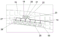
图1为本发明的一种多功能风力发电路灯结构示意图;1 is a schematic structural diagram of a multifunctional wind power generating circuit lamp of the present invention;
图2为图1中A处的结构放大图;Fig. 2 is an enlarged view of the structure at A place in Fig. 1;
图3为图1中B处的结构放大图;Figure 3 is an enlarged view of the structure at B in Figure 1;
图4为图1中C-C处的结构示意图。FIG. 4 is a schematic diagram of the structure at C-C in FIG. 1 .
具体实施方式Detailed ways
本说明书中公开的所有特征,或公开的所有方法或过程中的步骤,除了互相排斥的特征和/或步骤以外,均可以以任何方式组合。All features disclosed in this specification, or all disclosed steps in a method or process, may be combined in any way except mutually exclusive features and/or steps.
下面结合图1-4对本发明进行详细说明,为叙述方便,现对下文所说的方位规定如下:下文所说的上下左右前后方向与图1本身投影关系的上下左右前后方向一致。The present invention will be described in detail below in conjunction with Figures 1-4. For the convenience of description, the orientations mentioned below are now specified as follows: the up, down, left, right, front, and rear directions mentioned below are consistent with the up, down, left, right, front, and rear directions of the projection relationship of Figure 1 itself.
本发明装置的一种多功能风力发电路灯,包括动力壳体10和位于所述动力壳体10内的动力装置901,所述动力装置901包括转向动力腔14,所述转向动力腔14的下端壁固设有储电池13,所述储电池13的上端面固设有转向电机12,所述动力壳体10的左端面固设有路灯壳体15,所述动力装置901的上侧设有发电装置902,所述发电装置902包括转动壳体47,所述转动壳体47内设有转换腔34以及位于所述转换腔34左侧的发电腔45,所述发电腔45的上端壁靠近左侧位置固设有固定壳体30,所述固定壳体30内设有凸轮槽29,所述发电腔45的下端壁固设有发电机52,所述路灯壳体15内设有照明装置903,所述照明装置903包括电磁腔23和位于所述电磁腔23下侧的路灯槽53,且所述路灯槽53开口向下,所述动力壳体10的上端面固设有两个左右对称设置的固定轴40,所述转动壳体47的下端面设有位于两个所述固定轴40上侧且开口向下的两个T型滑槽41,所述固定轴40的上端面固设有与所述T型滑槽41滑动连接的滑块42,所述凸轮槽29的前后左右端壁均设有固定弹簧49,所述69内固设有插座槽50以及位于所述插座槽50内侧的插头31,所述插头31和所述插座槽50之间固定连接有插座48。A multifunctional wind power generating circuit lamp of the device of the present invention includes a
有益地,所述转向电机12的上侧动力连接有向上延伸且与所述动力壳体10转动连接的第一转动轴11,所述第一转动轴11的顶部末端固与所述转动壳体47的下端面固定连接,所述储电池13固定连接有第一导线55的一端。Beneficially, the upper side of the
有益地,所述路灯槽53内设有三个第一灯泡组26以及位于所述第一灯泡组26右侧的三个第二灯泡组25,所述第一灯泡组26通过第二导线27串联,所述电磁腔23的左端壁固设有电铁开关19,所述电铁开关19的右侧设有与所述电磁腔23滑动连接的左导电板21,所述左导电板21的右侧设有与所述电磁腔23固定连接的右导电板22,所述电铁开关19和所述左导电板21之间固定连接有电磁弹簧20,所述第二导线27的另一端与所述左导电板21的左端面固定连接,所述第二灯泡组25通过所述转向动力腔14串联,所述第一导线55的另一端固定连接于所述右导电板22的右端面。Beneficially, three
有益地,所述转换腔34内转动连接有向右延伸的第二转动轴36,所述第二转动轴36的右侧末端固定连接有位于所述转动壳体47右端面右侧的扇叶固定套51,所述扇叶固定套51上固设有三个均匀分布的扇叶18,所述第二转动轴36的左侧花键连接有花键套37,所述花键套37转动连接于滑板35上,所述滑板35的右端面与电磁开关38固定连接,所述电磁开关38与所述转换腔34的右端壁固定连接。Beneficially, a second rotating
有益地,所述花键套37的左侧花键连接有向左延伸且与所述转动壳体47转动连接的第三转动轴33,所述第三转动轴33的左侧末端固设有位于所述发电腔45内的第一锥齿轮32,所述发电机52的上侧动力连接有电量检测器46,所述电量检测器46上固设有固定标识44以及位于所述固定标识44上侧的第二锥齿轮39,且所述第二锥齿轮39与所述第一锥齿轮32啮合连接,所述发电腔45的左端壁固设有位于所述固定标识44左侧的电量检测器46。Beneficially, the left side of the
有益地,所述凸轮槽29内设有向上延伸且与所述转动壳体47转动连接的第四转动轴17,所述第四转动轴17的顶部末端固设有位于所述转动壳体47上端面上侧的风向标16,所述第四转动轴17的底部末端固设有位于所述凸轮槽29内的凸轮28,且所述凸轮28位于四个个所述固定弹簧49之间。Beneficially, the
初始状态下,第三转动轴33和第二转动轴36通过花键套37连接,左导电板21和右导电板22接触;In the initial state, the third rotating
开始工作时,风向标16在风力的作用下进行摆动,通过第四转动轴17带动凸轮28按压插头31,进而通过按压不同位置的左导电板21判断风的方向,此时转向电机12启动,第一转动轴11开始转动,将转动壳体47进行转动,进而将扇叶18转向有风力的一侧。When starting to work, the weather vane 16 swings under the action of the wind, and the fourth rotating
扇叶18在风的作用下转动,通过第二转动轴36、花键套37、第三转动轴33、第一锥齿轮32、第二锥齿轮39和电量检测器46的转动,带动第一锥齿轮32发电,同时电量检测器46通过固定标识44的转动圈数记录发电量。The
当天气暗下来,储电池13放电,将第一灯泡组26和第二灯泡组25点亮,进行照明,如果转动壳体47记录发电量较少时,电铁开关19启动,电磁弹簧20收缩,将左导电板21向左移动,使左导电板21和右导电板22断开,此时只有三个第二灯泡组25进行照明,节约电量,保证在无风或风力较小的天气下,照明的继续进行。When the weather gets dark, the
当储电池13内的电量储存满时,电磁开关38启动,带动滑板35向右移动,进而使花键套37和第三转动轴33脱离连接,第二转动轴36进行空转,防止储电池13过冲。When the power in the
以上所述,仅为发明的具体实施方式,但发明的保护范围并不局限于此,任何不经过创造性劳动想到的变化或替换,都应涵盖在发明的保护范围之内。因此,发明的保护范围应该以权利要求书所限定的保护范围为准。The above are only specific embodiments of the invention, but the protection scope of the invention is not limited to this, and any changes or substitutions that are not conceived of without creative work should be included within the protection scope of the invention. Therefore, the protection scope of the invention should be subject to the protection scope defined by the claims.
Claims (6)
Priority Applications (1)
| Application Number | Priority Date | Filing Date | Title |
|---|---|---|---|
| CN202010177090.7A CN111237700B (en) | 2020-03-13 | 2020-03-13 | A kind of multifunctional wind power circuit lamp |
Applications Claiming Priority (1)
| Application Number | Priority Date | Filing Date | Title |
|---|---|---|---|
| CN202010177090.7A CN111237700B (en) | 2020-03-13 | 2020-03-13 | A kind of multifunctional wind power circuit lamp |
Publications (2)
| Publication Number | Publication Date |
|---|---|
| CN111237700A true CN111237700A (en) | 2020-06-05 |
| CN111237700B CN111237700B (en) | 2020-10-23 |
Family
ID=70864767
Family Applications (1)
| Application Number | Title | Priority Date | Filing Date |
|---|---|---|---|
| CN202010177090.7A Active CN111237700B (en) | 2020-03-13 | 2020-03-13 | A kind of multifunctional wind power circuit lamp |
Country Status (1)
| Country | Link |
|---|---|
| CN (1) | CN111237700B (en) |
Citations (5)
| Publication number | Priority date | Publication date | Assignee | Title |
|---|---|---|---|---|
| JP2006302837A (en) * | 2005-04-25 | 2006-11-02 | Matsushita Electric Works Ltd | Lighting device, lighting fixture, lighting system |
| CA2862565A1 (en) * | 2012-02-08 | 2013-08-15 | Romo Wind Ag | Apparatus for adjusting the yaw of a wind turbine |
| CN106287514A (en) * | 2016-08-10 | 2017-01-04 | 李从宾 | The city electricity-saving lighting installation that a kind of new forms of energy and electric power coordinate |
| CN109356795A (en) * | 2018-09-29 | 2019-02-19 | 乐绪春 | A kind of power generator |
| CN110553209A (en) * | 2019-10-22 | 2019-12-10 | 诸暨平措照明科技有限公司 | An environment-friendly wind energy searchlight for construction site |
-
2020
- 2020-03-13 CN CN202010177090.7A patent/CN111237700B/en active Active
Patent Citations (5)
| Publication number | Priority date | Publication date | Assignee | Title |
|---|---|---|---|---|
| JP2006302837A (en) * | 2005-04-25 | 2006-11-02 | Matsushita Electric Works Ltd | Lighting device, lighting fixture, lighting system |
| CA2862565A1 (en) * | 2012-02-08 | 2013-08-15 | Romo Wind Ag | Apparatus for adjusting the yaw of a wind turbine |
| CN106287514A (en) * | 2016-08-10 | 2017-01-04 | 李从宾 | The city electricity-saving lighting installation that a kind of new forms of energy and electric power coordinate |
| CN109356795A (en) * | 2018-09-29 | 2019-02-19 | 乐绪春 | A kind of power generator |
| CN110553209A (en) * | 2019-10-22 | 2019-12-10 | 诸暨平措照明科技有限公司 | An environment-friendly wind energy searchlight for construction site |
Also Published As
| Publication number | Publication date |
|---|---|
| CN111237700B (en) | 2020-10-23 |
Similar Documents
| Publication | Publication Date | Title |
|---|---|---|
| CN212005468U (en) | Electric vehicle charging pile capable of storing energy by utilizing wind energy or solar street lamp | |
| CN109973909B (en) | A smart solar street lamp with charging function for municipal use | |
| CN205782513U (en) | A kind of multi-functional street lamp | |
| CN110319403A (en) | Energy-saving environment-friendly road lamp | |
| CN105066048A (en) | Novel efficient intelligent environment-friendly ecological navigation mark | |
| CN111237700B (en) | A kind of multifunctional wind power circuit lamp | |
| CN111404452B (en) | Device based on integration of photovoltaic technology and wind power generation technology | |
| CN213065935U (en) | A smart city street light based on the Internet of Things | |
| CN212204360U (en) | A solar LED street light with good wind resistance | |
| CN110762470B (en) | Solar street lamp with long-term guarantee conversion efficiency | |
| CN208817341U (en) | A solar street light with automatic tracking | |
| CN211574982U (en) | Intelligent LED lamp based on Internet of things | |
| CN114294607A (en) | A street lamp powered by light, wind and hydrogen new energy | |
| CN221197305U (en) | Solar intelligent street lamp capable of setting illumination time length | |
| CN206410026U (en) | A kind of energy saver of highway street lamp | |
| CN216744141U (en) | Energy-saving environment-friendly solar street lamp | |
| CN216790045U (en) | A wind-solar complementary energy-saving lamp | |
| CN2332961Y (en) | Autotracking solar heat collector | |
| CN207831195U (en) | A kind of dykes and dams energy-conserving road lamp along the river | |
| CN208431690U (en) | An LED lighting device whose lighting direction can be adjusted | |
| CN113847198A (en) | An intelligent wind water production system based on wind power generation | |
| CN218626563U (en) | Wind-solar complementary solar street lamp | |
| CN213362275U (en) | An intelligent integrated solar LED street light | |
| CN113431740B (en) | Intelligent wind energy storage street lamp | |
| CN218954687U (en) | a windmill light |
Legal Events
| Date | Code | Title | Description |
|---|---|---|---|
| PB01 | Publication | ||
| PB01 | Publication | ||
| SE01 | Entry into force of request for substantive examination | ||
| SE01 | Entry into force of request for substantive examination | ||
| GR01 | Patent grant | ||
| GR01 | Patent grant | ||
| TR01 | Transfer of patent right | ||
| TR01 | Transfer of patent right |
Effective date of registration: 20210510 Address after: No. 66, Jing Xi Road, Tianchang Economic Development Zone, Chuzhou, Anhui Province Patentee after: XINKE TECHNOLOGY Co.,Ltd. Address before: 311800 no.181 Anhua community, Anhua Town, Zhuji City, Shaoxing City, Zhejiang Province Patentee before: Zhuji pingcuo Lighting Technology Co.,Ltd. |