CN111237807A - A split type dry burning furnace - Google Patents
A split type dry burning furnace Download PDFInfo
- Publication number
- CN111237807A CN111237807A CN202010197805.5A CN202010197805A CN111237807A CN 111237807 A CN111237807 A CN 111237807A CN 202010197805 A CN202010197805 A CN 202010197805A CN 111237807 A CN111237807 A CN 111237807A
- Authority
- CN
- China
- Prior art keywords
- furnace
- oven
- fixedly connected
- dry combustion
- box body
- Prior art date
- Legal status (The legal status is an assumption and is not a legal conclusion. Google has not performed a legal analysis and makes no representation as to the accuracy of the status listed.)
- Pending
Links
Images


Classifications
-
- F—MECHANICAL ENGINEERING; LIGHTING; HEATING; WEAPONS; BLASTING
- F24—HEATING; RANGES; VENTILATING
- F24B—DOMESTIC STOVES OR RANGES FOR SOLID FUELS; IMPLEMENTS FOR USE IN CONNECTION WITH STOVES OR RANGES
- F24B1/00—Stoves or ranges
- F24B1/18—Stoves with open fires, e.g. fireplaces
- F24B1/182—Stoves with open fires, e.g. fireplaces with additional provisions for cooking
-
- F—MECHANICAL ENGINEERING; LIGHTING; HEATING; WEAPONS; BLASTING
- F24—HEATING; RANGES; VENTILATING
- F24B—DOMESTIC STOVES OR RANGES FOR SOLID FUELS; IMPLEMENTS FOR USE IN CONNECTION WITH STOVES OR RANGES
- F24B1/00—Stoves or ranges
- F24B1/18—Stoves with open fires, e.g. fireplaces
- F24B1/185—Stoves with open fires, e.g. fireplaces with air-handling means, heat exchange means, or additional provisions for convection heating ; Controlling combustion
- F24B1/189—Stoves with open fires, e.g. fireplaces with air-handling means, heat exchange means, or additional provisions for convection heating ; Controlling combustion characterised by air-handling means, i.e. of combustion-air, heated-air, or flue-gases, e.g. draught control dampers
- F24B1/1895—Stoves with open fires, e.g. fireplaces with air-handling means, heat exchange means, or additional provisions for convection heating ; Controlling combustion characterised by air-handling means, i.e. of combustion-air, heated-air, or flue-gases, e.g. draught control dampers flue-gas control dampers
-
- F—MECHANICAL ENGINEERING; LIGHTING; HEATING; WEAPONS; BLASTING
- F24—HEATING; RANGES; VENTILATING
- F24B—DOMESTIC STOVES OR RANGES FOR SOLID FUELS; IMPLEMENTS FOR USE IN CONNECTION WITH STOVES OR RANGES
- F24B1/00—Stoves or ranges
- F24B1/18—Stoves with open fires, e.g. fireplaces
- F24B1/191—Component parts; Accessories
Landscapes
- Engineering & Computer Science (AREA)
- Chemical & Material Sciences (AREA)
- Combustion & Propulsion (AREA)
- Mechanical Engineering (AREA)
- General Engineering & Computer Science (AREA)
Abstract
本发明公开了一种分体式干烧炉,属于民用采暖炉技术领域,其包括炉体和料仓,所述料仓包括仓体,所述仓体侧壁固定连接有与其内部连通的落料通道,所述落料通道远离仓体的一端延伸进入炉体内,所述仓体连接有将仓体内物料输送至落料通道内的送料结构,所述炉体和料仓呈分体设置并且两者之间留有间隙。本发明具有保护电器元件效果。
The invention discloses a split type dry burning furnace, which belongs to the technical field of civil heating furnaces. Channel, the end of the blanking channel away from the silo body extends into the furnace body, the silo body is connected with a feeding structure for conveying the material in the silo body to the blanking channel, the furnace body and the silo are arranged separately and two There is a gap between them. The present invention has the effect of protecting electrical components.
Description
技术领域technical field
本发明涉及民用采暖炉技术领域,更具体地说,它涉及一种分体式干烧炉。The invention relates to the technical field of civil heating furnaces, in particular to a split type dry burning furnace.
背景技术Background technique
干烧炉,燃烧燃料产生的热量,通过热辐射直接进行供暖,属于民用采暖炉的范畴。为了减少环境污染,现在干烧炉采用洁净煤或生物质作为原料,生物质燃料含硫量大多小于0.2%,熄灭时不用设置气体脱硫安装,降低了本钱,又利于环境的维护。Dry burning furnace, the heat generated by burning fuel, is directly heated by thermal radiation, which belongs to the category of civil heating furnace. In order to reduce environmental pollution, dry burning furnaces now use clean coal or biomass as raw materials. The sulfur content of biomass fuels is mostly less than 0.2%. There is no need to install gas desulfurization installations when burning, which reduces costs and is conducive to environmental maintenance.
目前,公开号为CN110094760A的中国发明专利申请公开了一种新型生物质颗粒干烧炉,包括炉体和储料室,所述炉体的顶部活动连接有炉盘,所述炉体的内部分别设置有燃烧室、配氧室和出火筒,所述储料室内部靠近底部的位置处设置有下料转板,所述储料室下端固定连接有驱动下料转板转动的驱动电机,所述储料室的底部设置有进料管,进料管延伸进入燃烧室内。At present, the Chinese invention patent application with the publication number of CN110094760A discloses a novel biomass particle dry burning furnace, which includes a furnace body and a material storage chamber. A furnace plate is movably connected to the top of the furnace body. A combustion chamber, an oxygen distribution chamber and a fire tube are provided. A blanking rotary plate is arranged inside the storage chamber at a position close to the bottom. The lower end of the storage chamber is fixedly connected with a drive motor that drives the rotation of the blanking rotary plate. The bottom of the storage chamber is provided with a feed pipe, and the feed pipe extends into the combustion chamber.
上述中的现有技术方案存在以下缺陷:生物质颗粒在燃烧室内燃烧时产生较高的热量,炉体的侧壁的温度可以到达400℃以上,在热辐射的作用下,储料室的温度也升高,可能导致驱动电机等电器元件的损坏。The above-mentioned prior art solutions have the following defects: when biomass particles are burned in the combustion chamber, a relatively high amount of heat is generated, and the temperature of the side wall of the furnace body can reach more than 400 ° C. Under the action of heat radiation, the temperature of the storage chamber It also rises, which may cause damage to electrical components such as the drive motor.
发明内容SUMMARY OF THE INVENTION
针对现有技术存在的不足,本发明的目的是提供一种分体式干烧炉,达到保护电器元件的目的。In view of the deficiencies in the prior art, the purpose of the present invention is to provide a split type dry burning furnace to achieve the purpose of protecting electrical components.
本发明的上述目的是通过以下技术方案得以实现的:一种分体式干烧炉,包括炉体和料仓,所述料仓包括仓体,所述仓体侧壁固定连接有与其内部连通的落料通道,所述落料通道远离仓体的一端延伸进入炉体内,所述仓体连接有将仓体内物料输送至落料通道内的送料结构,所述炉体和料仓呈分体设置并且两者之间留有间隙。The above object of the present invention is achieved through the following technical solutions: a split-type dry burning furnace, comprising a furnace body and a silo, the silo includes a silo body, and the side wall of the silo body is fixedly connected with a A blanking channel, the end of the blanking channel away from the silo body extends into the furnace body, the silo body is connected with a feeding structure for conveying the materials in the silo body to the blanking channel, and the furnace body and the silo are arranged separately And there is a gap between the two.
通过采用上述技术方案,使料仓和炉体分体设置,减小两者之间的热传递和热辐射,减少从炉体传递至料仓的热量,从而降低料仓的温度,降低安装于料仓的电器元件的损坏的可能性,保护电器元件。By adopting the above technical solution, the silo and the furnace body are arranged separately, reducing the heat transfer and heat radiation between the two, reducing the heat transferred from the furnace body to the silo, thereby reducing the temperature of the silo and reducing the installation in the silo. The possibility of damage to the electrical components of the silo, protect the electrical components.
本发明在一较佳示例中可以进一步配置为:所述落料通道靠近炉体一端呈倾斜设置,所述落料通道靠近炉体一端为其倾斜下端。In a preferred example of the present invention, it can be further configured that: the blanking channel is inclined at one end close to the furnace body, and the blanking channel has an inclined lower end at one end close to the furnace body.
通过采用上述技术方案,送料结构将生物质颗粒输送至落料通道内,在重力作用下沿着倾斜的落料通道滑入炉体内进行燃烧,倾斜设置的落料通道可以减少物料的滞留,可以有效降低落料通道内的生物质颗粒被点燃的可能性。By adopting the above technical solution, the feed structure transports the biomass particles into the blanking channel, and slides into the furnace body along the inclined blanking channel under the action of gravity for combustion. The inclined blanking channel can reduce the retention of materials, and can Effectively reduce the possibility of ignition of biomass particles in the blanking channel.
本发明在一较佳示例中可以进一步配置为:所述送料结构为螺旋送料机或者星型卸料机。In a preferred example of the present invention, it can be further configured that: the feeding structure is a screw feeder or a star unloader.
通过采用上述技术方案,利用螺旋送料机或者星型卸料机定时定量的送料,保持火焰燃烧的稳定性。By adopting the above technical scheme, the screw feeder or the star-shaped unloader is used to feed the material regularly and quantitatively, so as to maintain the stability of the flame combustion.
本发明在一较佳示例中可以进一步配置为:还包括暖气包,所述暖气包一端与炉体的出烟口连通,所述暖气包上端固定连接有排烟管,所述排烟管与室外连通。In a preferred example of the present invention, it can be further configured as follows: it further includes a heating pack, one end of the heating pack is connected with the smoke outlet of the furnace body, and a smoke exhaust pipe is fixedly connected to the upper end of the heating pack, and the smoke exhaust pipe is connected to the smoke outlet of the furnace body. Outdoor connectivity.
通过采用上述技术方案,烟气依次通过暖气包和排烟管排至室外,减少室内尾气的污染。By adopting the above technical solution, the flue gas is discharged to the outdoors through the heating pack and the flue gas exhaust pipe in turn, thereby reducing the pollution of indoor exhaust gas.
本发明在一较佳示例中可以进一步配置为:所述暖气包包括箱体,所述箱体固定连接有与其内部连通的连通管,所述连通管远离箱体的一端固定连接于炉体并且与其出烟口连通,所述箱体与炉体位于两个独立的室内。In a preferred example of the present invention, it can be further configured that: the heating pack includes a box body, the box body is fixedly connected with a communication pipe that communicates with the inside of the box body, and an end of the communication pipe remote from the box body is fixedly connected to the furnace body and In communication with its smoke outlet, the box body and the furnace body are located in two independent chambers.
通过采用上述技术方案,使炉体和暖气包呈分体设置,利用炉体和暖气包分被为两个独立的房间进行供暖,将干烧炉的燃烧产生的烟气中的余热进行利用,提升能源的利用率。By adopting the above technical solution, the furnace body and the radiator are set as separate bodies, the furnace body and the radiator are divided into two independent rooms for heating, and the waste heat in the flue gas generated by the combustion of the dry burning furnace is utilized, Improve energy efficiency.
本发明在一较佳示例中可以进一步配置为:所述箱体侧壁开设有烤箱口,所述箱体设置有烤箱结构,所述烤箱结构包括插接于烤箱口的烤架。In a preferred example of the present invention, it can be further configured that: the side wall of the box body is provided with an oven port, the case body is provided with an oven structure, and the oven structure includes a grill inserted into the oven port.
通过采用上述技术方案,可以将食物放置于烤架上,利用烟气的余热对食物进行烘烤,使干烧炉的功能更加全面,同时也提升能源的利用率。By adopting the above technical solution, the food can be placed on the grill, and the waste heat of the flue gas can be used to bake the food, so that the function of the dry burning furnace is more comprehensive, and the utilization rate of energy is also improved.
本发明在一较佳示例中可以进一步配置为:所述烤架远离箱体的一端固定连接有封闭烤箱口的封盖。In a preferred example of the present invention, it can be further configured that: one end of the grill away from the box body is fixedly connected with a cover for closing the oven opening.
通过采用上述技术方案,利用封盖封闭箱口,减少热量的流失,提升烤箱结构的烘烤温度。By adopting the above technical solution, the opening of the box is closed with a cover, so as to reduce the loss of heat and increase the baking temperature of the oven structure.
本发明在一较佳示例中可以进一步配置为:所述箱体内固定连接有一端开设有开口的导热套,所述导热套的开口与烤箱口连通。In a preferred example of the present invention, it can be further configured as follows: a heat-conducting sleeve with an opening at one end is fixedly connected to the box, and the opening of the heat-conducting sleeve communicates with the oven opening.
通过采用上述技术方案,利用导热套阻隔烟气和食物,避免烟气污染食物,烟气的热量通过导热套传递至导热套内,从而对食物进行加热。By adopting the above technical solution, the heat-conducting sleeve is used to block the smoke and the food, so as to prevent the smoke from contaminating the food, and the heat of the smoke is transferred into the heat-conducting sleeve through the heat-conducting sleeve, thereby heating the food.
本发明在一较佳示例中可以进一步配置为:所述导热套低于所述连通管靠近箱体一端的高度。In a preferred example of the present invention, it can be further configured that: the heat-conducting sleeve is lower than the height of the communicating pipe close to one end of the box.
通过采用上述技术方案,减少导热套对烟气的流动的影响,使烟气可以顺畅得从排烟管排至室外。By adopting the above technical scheme, the influence of the heat conduction jacket on the flow of the flue gas is reduced, so that the flue gas can be smoothly discharged from the exhaust pipe to the outdoors.
综上所述,本发明包括以下至少一种有益技术效果:To sum up, the present invention includes at least one of the following beneficial technical effects:
其一,使料仓和炉体分体设置,减小两者之间的热传递和热辐射,减少从炉体传递至料仓的热量,从而降低料仓的温度,降低安装于料仓的电器元件的损坏的可能性。First, separate the silo and the furnace body to reduce the heat transfer and heat radiation between the two and reduce the heat transferred from the furnace body to the silo, thereby reducing the temperature of the silo and reducing the amount of heat installed in the silo. Possibility of damage to electrical components.
其二,炉体和暖气包分体设置,可以实现分室多房间供暖,既干净卫生又安全可靠,使炉体位于客厅,使暖气包位于卧室,最大限度的避免了卧室居住人员煤气中毒的风险。Second, the furnace body and the radiator package are set separately, which can realize multi-room heating, which is clean, hygienic, safe and reliable. The furnace body is located in the living room, and the radiator package is located in the bedroom, which minimizes the risk of gas poisoning for the residents in the bedroom. .
其三,暖气包设置有烤箱结构,利用烟气的余热对食物进行烘烤,使干烧炉的功能更加全面,同时也提升能源的利用率。Third, the heating pack is equipped with an oven structure, which uses the waste heat of the flue gas to bake the food, so that the function of the dry burning furnace is more comprehensive, and the utilization rate of energy is also improved.
附图说明Description of drawings
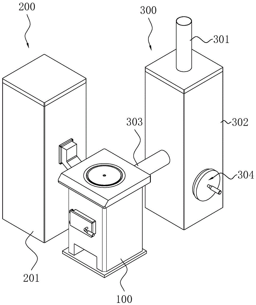
图1为本实施例的立体图;1 is a perspective view of this embodiment;
图2为本实施例用于展示料仓的剖面图;FIG. 2 is a cross-sectional view for showing a silo in this embodiment;
图3为本实施例用于展示烤箱结构的剖面示意图。FIG. 3 is a schematic cross-sectional view for showing the structure of the oven according to the present embodiment.
附图标记:100、炉体;200、料仓;201、仓体;202、隔板;203、落料通道;204、送料结构;300、暖气包;301、排烟管;302、箱体;303、连通管;304、烤箱结构;305、导热套;306、烤箱口;307、烤架;308、封盖;309、把手。Reference numerals: 100, furnace body; 200, silo; 201, silo body; 202, partition plate; 203, blanking channel; 204, feeding structure; 300, heating pack; 301, smoke exhaust pipe; 302,
具体实施方式Detailed ways
以下结合附图对本发明作进一步详细说明。The present invention will be further described in detail below with reference to the accompanying drawings.
实施例:如图1所示,为本发明公开的一种分体式干烧炉,包括炉体100和为炉体100提供生物质颗粒的料仓200,炉体100的排烟口连通有暖气包300,暖气包300上端固定连接有排烟管301,排烟管301与室外连通。料仓200将生物质颗粒输送中炉体100内进行燃烧,燃烧产生的热量用于采暖和烧水。燃烧后的烟气通过排烟口进入暖气包300内,然后再通过排烟管301排至室外。Example: As shown in FIG. 1 , it is a split type dry burning furnace disclosed in the present invention, comprising a
如图2所示,料仓200包括长方体状的仓体201,仓体201内固定连接有倾斜设置的隔板202。仓体201侧壁固定连接有落料通道203,落料通道203远离仓体201的一端向下倾斜并且延伸进入炉体100内。落料通道203靠近隔板202倾斜下端的一端的一侧,减少仓体201内残留的生物质颗粒。仓体201内连接有将料仓200内物料输送至落料通道203内的送料结构204,送料结构204为螺旋送料机。螺旋送料机固定连接于隔板202底部,其进料口与仓体201内部连通,其出口与落料通道203连通,螺旋送料机可以定时定量的送料,保持火焰燃烧的稳定性。送料结构204也可以是固定连接于隔板202倾斜下端的星型卸料机,其进料口与仓体201内部连通,其出口与落料通道203连通,星型卸料机将仓体201的生物质颗粒输送至落料通道203内时,可以始终保持落料通道203和仓体201隔绝,避免炉体100内燃烧产生的烟气通过落料通道203进入仓体201内,避免燃烧产生的高温烟气引燃仓体201内的生物质颗粒。As shown in FIG. 2 , the
如图1和图2所示,炉体100和料仓200呈分体设置并且两者之间留有间隙,减小两者之间的热传递和热辐射,减少从炉体100传递至料仓200的热量,从而降低料仓200的温度,降低安装于料仓200的电器元件的损坏的可能性。As shown in FIG. 1 and FIG. 2 , the
如图1所示,暖气包300包括箱体302,箱体302固定连接有与其内部连通的连通管303,连通管303远离箱体302的一端固定连接于炉体100并且与其出烟口连通,排烟管301固定连接于箱体302上端并且与其内部连通。箱体302与炉体100位于两个独立的房间内,两个房间呈相邻设置,连通管303穿过两个房间之间的墙壁。使炉体100和暖气包300分别为两个独立的房间进行供暖,将干烧炉的燃烧呈的烟气中的余热进行利用,提升能源的利用率。As shown in FIG. 1 , the
如图3所示,箱体302安装有烤箱结构304,烤箱结构304包括固定连接于箱体302内的导热套305,导热套305一端开设有开口,其开设有开口的一端与箱体302的内壁固定连接,箱体302侧壁开设有与导热套305开口连通的烤箱口306。导热套305内放置有烤架307,可以将食物放置于烤架307上,烟气的热量通过导热套305传递至导热套305内,从而对食物进行加热,利用导热套305阻隔烟气和食物,避免烟气污染食物。烤架307远离箱体302的一端固定连接有封闭烤箱口306的封盖308,封盖308远离烤架307的一端固定连接有把手309。As shown in FIG. 3 , the
如图3所示,导热套305的高度低于连通管303靠近箱体302一端的高度,减少导热套305对烟气的流动的影响,使烟气可以顺畅得从排烟管301排至室外。As shown in FIG. 3 , the height of the heat-conducting
本实施例的具体工作原理:炉体100和料仓200呈分体设置并且两者之间留有间隙,减小两者之间的热传递和热辐射,减少从炉体100传递至料仓200的热量,从而降低料仓200的温度,降低安装于料仓200的电器元件的损坏的可能性。The specific working principle of this embodiment: the
暖气包300安装有烤箱结构304,烟气的热量通过导热套305传递至导热套305内,从而对食物进行加热,使干烧炉的功能更加全面,同时也提升能源的利用率。The
本具体实施例仅仅是对本发明的解释,其并不是对本发明的限制,本领域技术人员在阅读完本说明书后可以根据需要对本实施例做出没有创造性贡献的修改,但只要在本发明的权利要求范围内都受到专利法的保护。This specific embodiment is only an explanation of the present invention, and it does not limit the present invention. Those skilled in the art can make modifications without creative contribution to the present embodiment as required after reading this specification, but as long as the rights of the present invention are used All claims are protected by patent law.
Claims (9)
Priority Applications (1)
| Application Number | Priority Date | Filing Date | Title |
|---|---|---|---|
| CN202010197805.5A CN111237807A (en) | 2020-03-19 | 2020-03-19 | A split type dry burning furnace |
Applications Claiming Priority (1)
| Application Number | Priority Date | Filing Date | Title |
|---|---|---|---|
| CN202010197805.5A CN111237807A (en) | 2020-03-19 | 2020-03-19 | A split type dry burning furnace |
Publications (1)
| Publication Number | Publication Date |
|---|---|
| CN111237807A true CN111237807A (en) | 2020-06-05 |
Family
ID=70870260
Family Applications (1)
| Application Number | Title | Priority Date | Filing Date |
|---|---|---|---|
| CN202010197805.5A Pending CN111237807A (en) | 2020-03-19 | 2020-03-19 | A split type dry burning furnace |
Country Status (1)
| Country | Link |
|---|---|
| CN (1) | CN111237807A (en) |
Citations (6)
| Publication number | Priority date | Publication date | Assignee | Title |
|---|---|---|---|---|
| ES277337U (en) * | 1982-01-11 | 1984-07-16 | Fondis Sa | Direct removal of flue gases in heating appliances of the closed type. |
| CN2209778Y (en) * | 1994-10-26 | 1995-10-11 | 陈元昌 | Environmental protection type separation warming stove |
| CN203880686U (en) * | 2014-06-10 | 2014-10-15 | 厦门中诚达生物科技有限公司 | Split type biomass burning machine |
| CN209431381U (en) * | 2018-12-16 | 2019-09-24 | 龙山顺天生物能源开发有限公司 | A kind of biomass steam producer |
| CN209966167U (en) * | 2019-03-18 | 2020-01-21 | 福佑科技(天津)有限公司 | Multifunctional oven |
| CN211694991U (en) * | 2020-03-19 | 2020-10-16 | 山东超万采暖设备有限公司 | Split type dry combustion furnace |
-
2020
- 2020-03-19 CN CN202010197805.5A patent/CN111237807A/en active Pending
Patent Citations (6)
| Publication number | Priority date | Publication date | Assignee | Title |
|---|---|---|---|---|
| ES277337U (en) * | 1982-01-11 | 1984-07-16 | Fondis Sa | Direct removal of flue gases in heating appliances of the closed type. |
| CN2209778Y (en) * | 1994-10-26 | 1995-10-11 | 陈元昌 | Environmental protection type separation warming stove |
| CN203880686U (en) * | 2014-06-10 | 2014-10-15 | 厦门中诚达生物科技有限公司 | Split type biomass burning machine |
| CN209431381U (en) * | 2018-12-16 | 2019-09-24 | 龙山顺天生物能源开发有限公司 | A kind of biomass steam producer |
| CN209966167U (en) * | 2019-03-18 | 2020-01-21 | 福佑科技(天津)有限公司 | Multifunctional oven |
| CN211694991U (en) * | 2020-03-19 | 2020-10-16 | 山东超万采暖设备有限公司 | Split type dry combustion furnace |
Similar Documents
| Publication | Publication Date | Title |
|---|---|---|
| CN101907292B (en) | Vertical environment-friendly boiler for triple dedusting burning wood and biomass particle fuel in boiler | |
| CN103666569B (en) | Biomass gasification system | |
| CN104595887A (en) | Automatic control type biomass energy baking device | |
| CN210197696U (en) | Split hot-blast stove | |
| CN104964439B (en) | A kind of air thermal insulation hot cyclone boiler | |
| CN102261739B (en) | Biomass energy hot blast stove | |
| CN202141190U (en) | Biomass energy hot-blast stove | |
| CN211694991U (en) | Split type dry combustion furnace | |
| CN211667857U (en) | Straw biological particle combustion furnace | |
| CN111237807A (en) | A split type dry burning furnace | |
| CN108253458A (en) | A kind of heating-cooking integral biomass combustion furnace | |
| CN204853957U (en) | Biological particle hot -blast furnace | |
| CN203132130U (en) | Novel hot blast stove for solid fuels | |
| CN202166047U (en) | Energy-saving and environment-friendly biomass heating furnace | |
| CN202898353U (en) | Biomass gasifying system | |
| CN100498078C (en) | Biomass multiple-purpose oven | |
| CN105091551A (en) | Biomass briquette hot blast heater of grain drying machine | |
| CN208269409U (en) | A kind of biologic matter particle fuel hot-air furnace | |
| CN202660732U (en) | Biomass fuel semi-gasification hot-blast stove for heating | |
| CN113566416A (en) | Biomass gasification intelligent heating and cooking stove | |
| CN205919310U (en) | Boiler wind channel | |
| CN221629785U (en) | Direct-fired drying furnace | |
| CN206846689U (en) | Biomass fuel tobacco leaf baking device | |
| CN206563309U (en) | Integration biomass drying room system for baking | |
| CN204535080U (en) | A kind of energy-saving and emission-reduction heating furnace |
Legal Events
| Date | Code | Title | Description |
|---|---|---|---|
| PB01 | Publication | ||
| PB01 | Publication | ||
| SE01 | Entry into force of request for substantive examination | ||
| SE01 | Entry into force of request for substantive examination | ||
| RJ01 | Rejection of invention patent application after publication | ||
| RJ01 | Rejection of invention patent application after publication |
Application publication date: 20200605 |