CN111281237A - Full-automatic hand washer - Google Patents
Full-automatic hand washer Download PDFInfo
- Publication number
- CN111281237A CN111281237A CN202010216161.XA CN202010216161A CN111281237A CN 111281237 A CN111281237 A CN 111281237A CN 202010216161 A CN202010216161 A CN 202010216161A CN 111281237 A CN111281237 A CN 111281237A
- Authority
- CN
- China
- Prior art keywords
- hand
- movable
- hand sanitizer
- assembly
- room
- Prior art date
- Legal status (The legal status is an assumption and is not a legal conclusion. Google has not performed a legal analysis and makes no representation as to the accuracy of the status listed.)
- Pending
Links
Images


Classifications
-
- A—HUMAN NECESSITIES
- A47—FURNITURE; DOMESTIC ARTICLES OR APPLIANCES; COFFEE MILLS; SPICE MILLS; SUCTION CLEANERS IN GENERAL
- A47K—SANITARY EQUIPMENT; ACCESSORIES THEREFOR, e.g. TOILET ACCESSORIES
- A47K7/00—Body washing or cleaning implements
- A47K7/04—Mechanical washing or cleaning devices, hand or mechanically, i.e. power operated
-
- A—HUMAN NECESSITIES
- A47—FURNITURE; DOMESTIC ARTICLES OR APPLIANCES; COFFEE MILLS; SPICE MILLS; SUCTION CLEANERS IN GENERAL
- A47K—SANITARY EQUIPMENT; ACCESSORIES THEREFOR, e.g. TOILET ACCESSORIES
- A47K10/00—Body-drying implements; Toilet paper; Holders therefor
- A47K10/48—Drying by means of hot air
-
- A—HUMAN NECESSITIES
- A47—FURNITURE; DOMESTIC ARTICLES OR APPLIANCES; COFFEE MILLS; SPICE MILLS; SUCTION CLEANERS IN GENERAL
- A47K—SANITARY EQUIPMENT; ACCESSORIES THEREFOR, e.g. TOILET ACCESSORIES
- A47K5/00—Holders or dispensers for soap, toothpaste or the like
- A47K5/06—Dispensers for soap
- A47K5/12—Dispensers for soap for liquid or pasty soap
Landscapes
- Health & Medical Sciences (AREA)
- Public Health (AREA)
- Engineering & Computer Science (AREA)
- Mechanical Engineering (AREA)
- Epidemiology (AREA)
- General Health & Medical Sciences (AREA)
- Body Washing Hand Wipes And Brushes (AREA)
Abstract
本发明公开了一种全自动洗手机,属于洗手机技术领域,包括:洗手机壳体、洗手液桶、清洗总成、废水桶、出水总成、烘干器及中央处理器,所述洗手机壳体内分别设有洗手液室、洗手室和废水室,所述洗手液桶通过洗手液室门板封闭在所述洗手液室内,所述废水桶通过废水室板门封闭在所述废水室内,所述清洗总成和出水总成分别对称布置在所述洗手室底部和顶部并通过洗手室门板封闭在所述洗手室内。本发明实现了无需自主操作来完成,解决了一些无法进行自主操作来完成洗手的人群独立完成洗手的目的,通过通信模块与远程终端的连接,实现了装置的物联网化,通过远程终端可以实时远程查看洗手机的工作状态,使洗手机整体机构更加简单科学。
The invention discloses a fully automatic cell phone washing machine, which belongs to the technical field of cell phone washing. A hand sanitizer room, a hand washing room and a waste water room are respectively arranged in the casing, the hand sanitizer bucket is closed in the hand sanitizer room through the hand sanitizer room door panel, and the waste water bucket is closed in the waste water room through the waste water room panel door, The cleaning assembly and the water outlet assembly are symmetrically arranged at the bottom and the top of the washroom, respectively, and are enclosed in the washroom by a washroom door panel. The invention realizes that it can be done without autonomous operation, and solves the purpose of washing hands independently for some people who cannot perform autonomous operation to complete handwashing. Remotely check the working status of the mobile phone, making the overall organization of the mobile phone more simple and scientific.
Description
技术领域technical field
本发明公开了一种全自动洗手机,属于洗手机技术领域。The invention discloses a fully automatic cell phone washing machine, which belongs to the technical field of cell phone washing.
背景技术Background technique
在医院洗手机很常见,医生和患者都需要经常进行手部清洗,减少手部细菌,然而医务人员洗手的步骤比较繁琐:Hand washing is very common in hospitals. Both doctors and patients need to wash their hands frequently to reduce hand bacteria. However, the steps for medical staff to wash their hands are cumbersome:
第一步,在流动水下,使双手充分淋湿。第二步,取适量皂液,均涂抹至整个手掌、手背手指和指缝。第三步,认真揉搓双手至少15秒钟,应注意清洗双手所有皮肤,包括指背、指尖和指缝,具体揉搓步骤为:1、掌心相对,手指并拢,相互揉搓;2、手心对手背沿指缝相互揉搓,交换进行;3、掌心相对,双手交叉指缝相互揉搓;4、弯曲手指使关节在另一手掌心旋转揉搓,交换进行;5、右手握住左手大拇指旋转揉搓,交换进行;6、将五个手指尖并拢放在另手掌心旋转揉搓,交换进行。第四步:在流动水下彻底冲净双手,擦干,取适量护手液护肤。The first step is to get your hands fully wet under running water. The second step is to take an appropriate amount of soap and apply it to the entire palm, back of the hand, fingers and between the fingers. The third step is to rub your hands carefully for at least 15 seconds. Care should be taken to clean all the skin of your hands, including the backs of your fingers, the tips of your fingers and the gaps between your fingers. The specific rubbing steps are: 1. The palms face each other, fingers close together, and rub each other; 2. The palms of the hands are on the back of the hand 3. The palms face each other and the fingers cross each other; 4. Bend the fingers to make the joints in the other palm rotate and rub, and the exchange is performed; 5. Hold the left thumb with the right hand and rotate and rub, and the exchange is performed ; 6. Put the five fingertips close together on the palm of the other hand and rotate and knead, and then exchange. Step 4: Rinse your hands thoroughly under running water, dry them, and take an appropriate amount of hand lotion for skin care.
现有的洗手机功能多种多样,基本上都具有普通的清洗、消毒和烘干功能,无法对手背缝隙、指甲缝隙以及大拇指间缝隙等进行清洗,众所周知,这些缝隙中窝藏细菌的“重要场所”,特别是指甲缝隙,在1克指甲垢里约有38—40亿个细菌,其中,可引起人们患病的细菌、病毒如痢疾杆菌、伤寒杆菌、大肠杆菌、肝炎病毒等,可达30余种;另外,还有许多寄生虫卵。如果想到对这些缝隙进行彻底清洗需要人自主操作来完成,对于一些无法进行自主来完成洗手的人群来说还是无法完成洗手的目的,而且现有的洗手机无法实时远程查看工作状态,如何时添加杀菌洗手液等。The existing hand washing functions have various functions. Basically, they have ordinary cleaning, disinfection and drying functions. They cannot clean the gaps on the back of the hand, the gaps between the nails, and the gaps between the thumbs. As we all know, these gaps harbor bacteria. There are about 3.8-4 billion bacteria in 1 gram of nail tartar, among them, the bacteria and viruses that can cause people to get sick, such as Shigella, Typhoid Bacillus, Escherichia coli, Hepatitis virus, etc., can reach More than 30 species; in addition, there are many parasite eggs. If it is thought that the thorough cleaning of these gaps needs to be done by human beings, it is still impossible for some people who cannot do their own handwashing to complete the purpose of handwashing, and the existing mobile phones cannot remotely check the working status in real time. How to add Antiseptic hand sanitizer, etc.
发明内容SUMMARY OF THE INVENTION
本发明的目的在于解决现有的洗手机无法对双手局部缝隙进行清洗及无法实时远程查看工作状态的问题,提出一种可以对双手局部缝隙进行全方位清洗及实时远程查看工作状态的全自动洗手机。The purpose of the present invention is to solve the problems that the existing hand washers cannot clean the local gaps of the hands and cannot check the working state remotely in real time, and propose a fully automatic washing machine that can clean the partial gaps of the hands in an all-round way and check the working state remotely in real time. cell phone.
本发明所要解决的问题是由以下技术方案实现的:The problem to be solved by this invention is realized by the following technical solutions:
一种全自动洗手机,包括:洗手机壳体、洗手液桶、清洗总成、废水桶、出水总成、烘干器及中央处理器,所述洗手机壳体内分别设有洗手液室、洗手室和废水室,所述洗手液桶通过洗手液室门板封闭在所述洗手液室内,所述废水桶通过废水室板门封闭在所述废水室内,所述清洗总成和出水总成分别对称布置在所述洗手室底部和顶部并通过洗手室门板封闭在所述洗手室内,所述洗手液桶通过洗手液管总成与所述洗手室连通,所述废水桶通过废水管与所述洗手室连通,所述烘干器设置在所述洗手室顶部,所述中央处理器分别与两个所述清洗总成和烘干器电连接;A fully automatic hand washing machine, comprising: a hand washing machine casing, a hand sanitizer bucket, a cleaning assembly, a waste water bucket, a water outlet assembly, a dryer and a central processing unit. A hand washing room and a waste water room, the hand sanitizer bucket is enclosed in the hand sanitizer room through the hand sanitizer room door panel, the waste water bucket is closed in the waste water room through the waste water room panel door, the cleaning assembly and the water outlet assembly are respectively Symmetrically arranged at the bottom and top of the washing room and closed in the washing room through the washing room door panel, the hand sanitizer bucket is communicated with the washing room through a hand sanitizer pipe assembly, and the waste water bucket is connected with the The washing room is connected, the dryer is arranged on the top of the washing room, and the central processing unit is electrically connected to the two cleaning assemblies and the dryer respectively;
所述出水总成包括:风车喷头支架和螺旋喷嘴,所述风车喷头支架喷口均沿同一旋向倾斜设置,所述风车喷头支架能够绕自身轴线自转,所述螺旋喷嘴与所述风车喷头支架的出水口相连接,所述出水总成通过连通水管与所述洗手机壳体外界相连;The water outlet assembly includes: a windmill nozzle bracket and a spiral nozzle, the nozzles of the windmill nozzle bracket are all inclined along the same rotational direction, the windmill nozzle bracket can rotate around its own axis, and the spiral nozzle and the windmill nozzle bracket are connected. the water outlet is connected, and the water outlet assembly is connected to the outside of the phone washer casing through a communication pipe;
所述清洗总成由移动总成、两个活动转刷组件和固定转刷组件组成,所述移动总成包括:洗手底架、导杆、中间架、两个移动架、电动缸、中间转动杆和两个旋转杆,所述导杆两端固定搭载在洗手底架上,所述中间架固定在所述导杆中部,两个所述移动架分别对称布置在所述中间架两侧且可在所述光杆上移动,所述移动架与所述中间架通过电缸相连接,所述中间转动杆可旋转设置在所述中间架一侧,所述中间转动杆的两端分别与两个所述旋转杆的一端铰接,另一端分别与两个所述移动架的一侧铰接,两个所述活动转刷组件分别相对布置在两个所述移动架远离两个所述旋转杆的另一侧,所述固定转刷组件布置在两个所述活动转刷组件之间且固定在所述洗手底架上,所述洗手室门板上设置有洗手入口与所述清洗总成相对应。The cleaning assembly is composed of a moving assembly, two movable rotating brush assemblies and a fixed rotating brush assembly. The moving assembly includes: a hand-washing chassis, a guide rod, a middle frame, two moving frames, an electric cylinder, an intermediate rotation rod and two rotating rods, the two ends of the guide rod are fixedly mounted on the hand-washing bottom frame, the middle frame is fixed on the middle of the guide rod, and the two movable frames are symmetrically arranged on both sides of the middle frame and It can move on the polished rod, the moving frame is connected with the intermediate frame through an electric cylinder, the intermediate rotating rod can be rotatably arranged on one side of the intermediate frame, and the two ends of the intermediate rotating rod are respectively connected to the two sides. One end of each of the rotating rods is hinged, and the other end is hinged with one side of the two moving frames respectively. The two movable rotating brush assemblies are respectively arranged opposite to the two moving frames away from the two rotating rods. On the other side, the fixed rotating brush assembly is arranged between the two movable rotating brush assemblies and is fixed on the hand washing chassis, and the washing room door panel is provided with a hand washing entrance corresponding to the cleaning assembly .
优选的是,所述连通水管上设有出水电磁阀且与所述中央处理器电连接,所述出水总成还包括出水光电传感器,所述移动总成还包括清洗刷光电传感器,所述烘干器上设有烘干光电传感器,所述出水光电传感器、烘干光电传感器和清洗刷光电传感器分别设置在所述洗手室内且与所述中央处理器电连接。Preferably, a water outlet solenoid valve is provided on the communicating water pipe and is electrically connected to the central processing unit, the water outlet assembly further includes a water outlet photoelectric sensor, the moving assembly further includes a cleaning brush photoelectric sensor, the drying A drying photoelectric sensor is arranged on the dryer, and the water outlet photoelectric sensor, the drying photoelectric sensor and the cleaning brush photoelectric sensor are respectively arranged in the washing room and electrically connected with the central processing unit.
优选的是,两个所述活动转刷组件结构相同,包括:若干根活动刷毛、活动转盘、活动电机、活动散热板和活动架,所述活动电机固定在所述活动架上,所述活动转盘中部固定在所述活动电机的主轴上,若干根所述活动刷毛固定在所述活动转盘远离所述活动电机的一侧,所述活动散热板固定在所述活动架上,所述固定转刷组件包括:若干根指尖刷毛、指尖转盘、指尖电机、指尖散热板和指尖固定架,所述指尖电机固定在所述指尖固定架上,所述指尖转盘中部固定在所述指尖电机的主轴上,若干根所述指尖刷毛固定在所述指尖转盘远离所述指尖电机的一侧,所述指尖散热板固定在所述指尖固定架上,所述若干根指尖刷毛与若干根活动刷毛呈直角,所述活动刷毛外径比指尖刷毛大,所述活动电机和指尖电机分别与所述中央处理器电连接。Preferably, the two movable rotating brush assemblies have the same structure, including: a plurality of movable brush bristles, a movable turntable, a movable motor, a movable cooling plate and a movable frame, the movable motor is fixed on the movable frame, and the movable motor is fixed on the movable frame. The middle part of the turntable is fixed on the main shaft of the movable motor, a plurality of the movable bristles are fixed on the side of the movable turntable away from the movable motor, the movable heat dissipation plate is fixed on the movable frame, and the fixed rotating plate is fixed on the movable frame. The brush assembly includes: a number of fingertip bristles, a fingertip turntable, a fingertip motor, a fingertip heat sink and a fingertip fixing frame, the fingertip motor is fixed on the fingertip fixing frame, and the middle part of the fingertip turntable is fixed On the main shaft of the fingertip motor, a plurality of the fingertip bristles are fixed on the side of the fingertip turntable away from the fingertip motor, and the fingertip cooling plate is fixed on the fingertip fixing frame, The plurality of fingertip bristles are at right angles to the plurality of movable bristles, the outer diameter of the movable bristles is larger than that of the fingertip bristles, and the movable motor and the fingertip motor are respectively electrically connected to the central processing unit.
优选的是,所述洗手液管总成包括:洗手液管、洗手液电磁阀和洗手液喷嘴,所述洗手液电磁阀与所述中央处理器电连接,所述洗手液管两端分别与洗手液电磁阀的一端和洗手液桶连接,所述洗手液电磁阀的另一端与洗手液喷嘴连接,所述洗手液喷嘴呈Y形布置,所述洗手液喷嘴一端与所述洗手液电磁阀的另一端连接,所述洗手液喷嘴的两个分支端与所述清洗总成相对应。Preferably, the hand sanitizer pipe assembly includes: a hand sanitizer pipe, a hand sanitizer solenoid valve and a hand sanitizer nozzle, the hand sanitizer solenoid valve is electrically connected to the central processing unit, and both ends of the hand sanitizer pipe are respectively connected to One end of the hand sanitizer solenoid valve is connected to the hand sanitizer bucket, the other end of the hand sanitizer solenoid valve is connected to the hand sanitizer nozzle, the hand sanitizer nozzle is arranged in a Y shape, and one end of the hand sanitizer nozzle is connected to the hand sanitizer solenoid valve The other end of the hand sanitizer nozzle is connected to the other end, and the two branch ends of the hand sanitizer nozzle correspond to the cleaning assembly.
优选的是,所述洗手液桶的侧面设有洗手液液面光电传感器,所述洗手液管总成还包括洗手液光电传感器,其设置在所述洗手液电磁阀上,所述废水桶侧面分别设有水桶液面光电传感器,所述洗手液液面光电传感器、洗手液光电传感器和水桶液面光电传感器分别与所述中央处理器电连接。Preferably, a hand sanitizer liquid level photoelectric sensor is provided on the side of the hand sanitizer bucket, and the hand sanitizer pipe assembly further includes a hand sanitizer photoelectric sensor, which is arranged on the hand sanitizer solenoid valve, and the side of the waste water bucket is provided with a hand sanitizer photoelectric sensor. A water bucket liquid level photoelectric sensor is respectively provided, and the hand sanitizer liquid level photoelectric sensor, the hand sanitizer photoelectric sensor and the water bucket liquid level photoelectric sensor are respectively electrically connected to the central processing unit.
优选的是,所述洗手液桶、清洗总成、废水桶、出水总成、烘干器、洗手入口分别设置有两个且相对应对称布置在所述洗手机壳体内。Preferably, the hand sanitizer bucket, the cleaning assembly, the waste water bucket, the water outlet assembly, the dryer and the hand washing inlet are respectively provided with two and are relatively symmetrically arranged in the mobile phone casing.
优选的是,所述洗手液室、洗手室和废水室内均设有湿度传感器且通过通风口相连通,所述洗手机壳体上设有通孔,所述风扇设置在所述通孔内,所述通孔大小与所述风扇外径相对应,所述湿度传感器和风扇分别与所述中央处理器电连接。Preferably, the hand sanitizer room, the hand washing room and the waste water room are all provided with humidity sensors and communicated with each other through ventilation openings, the mobile phone case is provided with a through hole, and the fan is arranged in the through hole, The size of the through hole corresponds to the outer diameter of the fan, and the humidity sensor and the fan are respectively electrically connected to the central processing unit.
优选的是,所述洗手入口形状为圆形、矩形或多边形等,所述洗手入口内部的一侧设有密封门总成,所述密封门总成包括移动滑槽、密封门、密封门电动缸和密封门光电传感器,所述移动滑槽对称布置在所述洗手入口的两侧,所述密封门可移动设置在所述移动滑槽上,所述密封门通过密封门电动缸与所述洗手室门板相连,所述密封门光电传感器设置在所述洗手室门板外侧与所述洗手入口相邻,所述密封门电动缸和密封门光电传感器分别与所述中央处理器电连接。Preferably, the shape of the hand-washing entrance is a circle, a rectangle or a polygon, and a sealing door assembly is provided on one side of the interior of the hand-washing entrance, and the sealing door assembly includes a moving chute, a sealing door, and an electric sealing door. cylinder and sealing door photoelectric sensor, the moving chute is symmetrically arranged on both sides of the hand washing entrance, the sealing door is movably arranged on the moving chute, and the sealing door is connected to the The door panel of the washroom is connected, the photoelectric sensor of the sealed door is arranged on the outside of the door of the washroom and adjacent to the entrance of the handwashing, and the electric cylinder of the airtight door and the photoelectric sensor of the airtight door are respectively electrically connected to the central processing unit.
优选的是,还包括通信模块,其与所述中央处理器电连接,所述中央处理器通过所述通信模块与远程终端连接。Preferably, it also includes a communication module, which is electrically connected to the central processing unit, and the central processing unit is connected to the remote terminal through the communication module.
本发明相对于现有而言具有的有益效果:The beneficial effects that the present invention has relative to the existing:
1、通过活动转刷组件结构中的活动刷毛对手部两侧上的缝隙进行清洗,通过采用固定转刷组件中的指尖刷毛对手部指尖和指甲缝隙进行清洗,从而可以清洗掉缝隙中窝藏细菌,使手部更加清洁,再通过移动总成电动缸使活动转刷组件和固定转刷组件配合移动,实现了无需自主操作来完成,解决了一些无法进行自主操作来完成洗手的人群独立完成洗手的目的。1. Clean the gaps on both sides of the hand with the movable bristles in the structure of the movable rotating brush assembly, and use the fingertip bristles in the fixed rotating brush assembly to clean the gaps between the fingertips and nails of the hand, so as to clean the gaps hidden in the gaps Bacteria, make hands cleaner, and then move the movable brush assembly and the fixed rotating brush assembly through the electric cylinder of the mobile assembly, which can be completed without autonomous operation, and solved some people who cannot perform autonomous operation to complete handwashing independently. Purpose of hand washing.
2、通过采用密封门总成可以把洗手机的内部进行封闭,当需要使用洗手机时,密封门光电传感器检测到手部时,密封门电动缸带动密封门移动,从而把洗手入口打开,防止外界空气接触,减少了细菌滋生的可能。2. The interior of the hand washing machine can be sealed by using the sealing door assembly. When the hand washing machine needs to be used, when the photoelectric sensor of the sealing door detects the hand, the electric cylinder of the sealing door drives the sealing door to move, thereby opening the hand washing entrance and preventing the outside world. Air contact reduces the possibility of bacterial growth.
3、通过通信模块与远程终端的连接,实现了装置的物联网化,通过远程终端可以实时远程查看洗手机的工作状态,使洗手机整体机构更加简单科学,符合现在设计要求。3. Through the connection between the communication module and the remote terminal, the Internet of Things of the device is realized, and the working status of the mobile phone can be remotely checked in real time through the remote terminal, which makes the overall mechanism of the mobile phone washing more simple and scientific, and meets the current design requirements.
附图说明Description of drawings
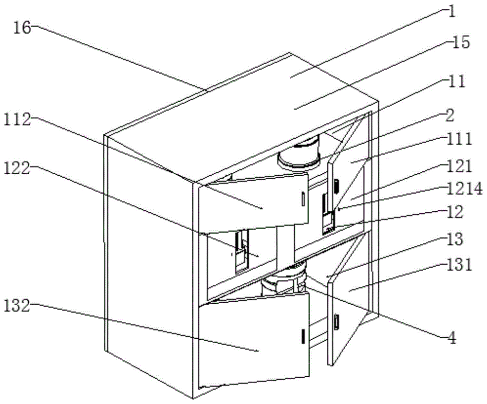
图1是本发明的等轴侧视图。Figure 1 is an isometric view of the present invention.
图2是本发明的结构示意图。Figure 2 is a schematic structural diagram of the present invention.
图3是本发明的后视图。Figure 3 is a rear view of the present invention.
图4是本发明部分结构等轴侧视图。Figure 4 is an isometric view of a portion of the structure of the present invention.
图5是本发明另一角度的部分结构等轴侧视图。Figure 5 is an isometric view of a partial structure from another angle of the present invention.
图6是本发明第一清洗总成的等轴侧视图。Figure 6 is an isometric view of the first cleaning assembly of the present invention.
图7是本发明移动总成的等轴侧视图。Figure 7 is an isometric view of the movement assembly of the present invention.
图8是本发明固定转刷组件的等轴侧视图。Figure 8 is an isometric view of the stationary rotating brush assembly of the present invention.
图9是本发明第一活动转刷组件的等轴侧视图。Figure 9 is an isometric view of the first movable rotating brush assembly of the present invention.
图10是本发明第一洗手液桶的等轴侧视图。Figure 10 is an isometric view of the first hand sanitizer bucket of the present invention.
图11是本发明第一废水桶的等轴侧视图。Figure 11 is an isometric view of the first waste bucket of the present invention.
图12是本发明第一洗手液管总成的等轴侧视图。Figure 12 is an isometric view of the first hand sanitizer tube assembly of the present invention.
图13是本发明第一出水总成的等轴侧视图。Figure 13 is an isometric view of the first water outlet assembly of the present invention.
图14是本发明第一密封门总成的等轴侧视图。Figure 14 is an isometric view of the first sealed door assembly of the present invention.
图15是本发明电气连接框架图。Figure 15 is a frame diagram of the electrical connection of the present invention.
其中,1-洗手机壳体,11-洗手液室,111-第一洗手液室门板,112-第二洗手液室门板,12-洗手室,121-第一洗手室门板,1211-移动滑槽,1212-密封门,1213-密封门电动缸,1214-密封门光电传感器,122-第二洗手室门板,13-废水室,131-第一废水室板门,132-第二废水室板门,14-排污口,15-机身,16-后盖,17-第一隔板,171-第一通风孔,18-第二隔板,181-第二通风孔,2-洗手液桶,21-第一洗手液桶,211-洗手液盖体,2111-洗手液通气孔,212-洗手液桶体,213-洗手液液面光电传感器,22-第二洗手液桶,23-第一洗手液管总成,231-洗手液管,232-洗手液电磁阀,233-洗手液喷嘴,234-洗手液光电传感器,24-第二洗手液管总成,3-清洗总成,31-第一清洗总成,311-移动总成,3111-洗手底架,3112-第一移动架,3113-中间架,3114-第二移动架,3115-第一旋转杆,3116-中间转动杆,3117-第二旋转杆,3118-电动缸,3119-导杆,312-固定转刷组件,3121-指尖散热板,3122-指尖固定架,3123-指尖转盘,3124-指尖刷毛,313-第一活动转刷组件,3131-活动散热板,3132-活动架,3133-第一活动转盘,3134-第二活动转盘,3135-活动刷毛,314-第二活动转刷组件,315-光栅传感器,32-第一清洗总成,4-废水桶,41-第一废水桶,411-废水接口,412-水桶液面光电传感器,413-把手,414-废水桶体,42-第二废水桶,43-第一废水管,44-第二废水管,5-风扇,6-烘干器,61-第一烘干器,62-第二烘干器,7-出水总成,71-第一出水总成,711-风车喷头支架,712-螺旋喷嘴,72-第二出水总成,73-通水管,74-出水电磁阀。Among them, 1- mobile phone case, 11- hand sanitizer room, 111- first hand sanitizer room door panel, 112- second hand sanitizer room door panel, 12- hand-washing room, 121- first hand-washing room door panel, 1211- mobile sliding Tank, 1212-Sealed Door, 1213-Sealed Door Electric Cylinder, 1214-Sealed Door Photoelectric Sensor, 122-Second Washroom Door Panel, 13-Waste Water Chamber, 131-First Wastewater Chamber Panel Door, 132-Second Wastewater Chamber Panel door, 14-sewage outlet, 15-body, 16-back cover, 17-first partition, 171-first ventilation hole, 18-second partition, 181-second ventilation hole, 2-hand sanitizer bucket , 21-first hand sanitizer bucket, 211-hand sanitizer cover, 2111-hand sanitizer vent, 212-hand sanitizer bucket, 213-hand sanitizer liquid level photoelectric sensor, 22-second hand sanitizer bucket, 23-first A hand sanitizer pipe assembly, 231-hand sanitizer pipe, 232-hand sanitizer solenoid valve, 233-hand sanitizer nozzle, 234-hand sanitizer photoelectric sensor, 24-second hand sanitizer pipe assembly, 3-washing assembly, 31 -1st cleaning assembly, 311-moving assembly, 3111-washing base frame, 3112-first moving frame, 3113-intermediate frame, 3114-second moving frame, 3115-first rotating rod, 3116-intermediate rotating rod , 3117-Second rotating rod, 3118-Electric cylinder, 3119-Guide rod, 312-Fixed rotating brush assembly, 3121-Fingertip cooling plate, 3122-Fingertip holder, 3123-Fingertip turntable, 3124-Fingertip bristles , 313- the first movable rotating brush assembly, 3131- movable cooling plate, 3132- movable frame, 3133- the first movable rotating plate, 3134- the second movable rotating plate, 3135- movable bristles, 314- the second movable rotating brush assembly, 315 - Grating sensor, 32- first cleaning assembly, 4- waste water bucket, 41- first waste water bucket, 411- waste water interface, 412- water bucket liquid level photoelectric sensor, 413- handle, 414- waste water bucket body, 42- No. Two waste water buckets, 43-first waste water pipe, 44-second waste water pipe, 5-fan, 6-dryer, 61-first dryer, 62-second dryer, 7-water outlet assembly, 71- First water outlet assembly, 711- Windmill nozzle bracket, 712- Spiral nozzle, 72- Second water outlet assembly, 73- Water outlet pipe, 74- Water outlet solenoid valve.
具体实施方式Detailed ways
以下根据附图1-15对本发明做进一步说明:The present invention is further described below according to accompanying drawings 1-15:
下面将结合附图对本发明的技术方案进行清楚、完整地描述,显然,所描述的实施例是本发明一部分实施例,而不是全部的实施例。基于本发明中的实施例,本领域普通技术人员在没有做出创造性劳动前提下所获得的所有其他实施例,都属于本发明保护的范围。The technical solutions of the present invention will be clearly and completely described below with reference to the accompanying drawings. Obviously, the described embodiments are a part of the embodiments of the present invention, but not all of the embodiments. Based on the embodiments of the present invention, all other embodiments obtained by those of ordinary skill in the art without creative efforts shall fall within the protection scope of the present invention.
在本发明的描述中,需要说明的是,术语“中心”、“上”、“下”、“左”、“右”、“竖直”、“水平”、“内”、“外”等指示的方位或位置关系为基于附图所示的方位或位置关系,仅是为了便于描述本发明和简化描述,而不是指示或暗示所指的装置或元件必须具有特定的方位、以特定的方位构造和操作,因此不能理解为对本发明的限制。In the description of the present invention, it should be noted that the terms "center", "upper", "lower", "left", "right", "vertical", "horizontal", "inner", "outer", etc. The indicated orientation or positional relationship is based on the orientation or positional relationship shown in the accompanying drawings, which is only for the convenience of describing the present invention and simplifying the description, rather than indicating or implying that the indicated device or element must have a specific orientation or a specific orientation. construction and operation, and therefore should not be construed as limiting the invention.
在本发明的描述中,需要说明的是,除非另有明确的规定和限定,术语“安装”、“相连”、“连接”应做广义理解,例如,可以是固定连接,也可以是可拆卸连接,或一体地连接;可以是机械连接,也可以是电连接;可以是直接相连,也可以通过中间媒介间接相连,可以是两个元件内部的连通。对于本领域的普通技术人员而言,可以具体情况理解上述术语在本发明中的具体含义。In the description of the present invention, it should be noted that the terms "installed", "connected" and "connected" should be understood in a broad sense, unless otherwise expressly specified and limited, for example, it may be a fixed connection or a detachable connection Connection, or integral connection; can be mechanical connection, can also be electrical connection; can be directly connected, can also be indirectly connected through an intermediate medium, can be internal communication between two elements. For those of ordinary skill in the art, the specific meanings of the above terms in the present invention can be understood in specific situations.
如图1-5所示,本发明第一实施例在现有技术的基础上提供了一种全自动洗手机,包括:洗手机壳体1、洗手液桶2、清洗总成3、废水桶4、出水总成7、烘干器6及中央处理器。洗手机壳体1包括相扣合的机身15和后盖16,后盖16通过螺栓固定在机身15上,方便维修洗手机内部机构。洗手机壳体1通过第一隔板和第二隔板把内部分别布置为三层,由上到下分别为洗手液室11、洗手室12和废水室13。洗手液桶2和废水桶4分别放置在对应的洗手液室11和废水室13内,清洗总成3和出水总成7分别对称布置在洗手室12底部和顶部。洗手液桶2通过洗手液管总成与洗手室11连通,用于洗手时用洗手液对手部进行杀菌消毒。废水桶4通过废水管与洗手室12连通,用于洗完手后的废水从废水口通过废水管流进废水桶4内,在没有任何排污条件的情况下使用洗手机时,洗完手后的废水属于生活污水,其中的有机物极不稳定,容易腐化而产生恶臭。细菌和病原体以生活污水中有机物为营养而大量繁殖,可导致传染病蔓延流行。因此需要集中收集处理。这样,可以不随意排放污水,达到环保的目的。烘干器6安装在洗手室12顶部,用于洗完手后对手部进行烘干处理,接下来将洗手机的各部分进行详细说明。As shown in Figures 1-5, the first embodiment of the present invention provides a fully automatic hand washing machine based on the prior art, including: a hand
首先介绍一下清洗总成3,为了可以在使用洗手机时让人体两只双手同时清洗,本发明把洗手液室11中间放置了中间隔板,从而可以把洗手液室11分为两个洗手液室11。因此清洗总成3也包括第一清洗总成31和第一清洗总成32,分别对称安装在用中间隔板分为两个洗手液室11洗手液室11内。第一清洗总成31和第一清洗总成32结构相同,所以本发明在论述的时候以第一清洗总成31为例进行详细说明。如图6所示,第一清洗总成31由移动总成311、第一活动转刷组件313、第二活动转刷组件314和固定转刷组件312组成,第一活动转刷组件313、第一活动转刷组件314和固定转刷组件312分别安装在移动总成311上。First, the cleaning assembly 3 will be introduced. In order to allow the two hands of the human body to be washed at the same time when using the hand washing machine, the present invention places a middle partition plate in the middle of the
接下来首先对移动总成311进行详细说明,如图7所示,移动总成311包括:洗手底架3111、导杆3119、中间架3113、第一移动架3112、第二移动架3114、电动缸3118、中间转动杆3116、第一旋转杆3115和第二旋转杆3117,洗手底架3111为矩形框架,其宽度小于或等于中间隔板到洗手机壳体1内部一侧的侧板长度,因此洗手底架3111通过螺栓固定或者焊接等固定方式固定在第二隔板上,两根导杆3119的两端通过螺栓固定搭载洗手底架3111中间框架内,中间架3113通过焊接固定在两根导杆3119中部,第一移动架3112和第二移动架3114可移动的套设在两根导杆3119上且分别对称布置在中间架3113两侧,为了做到轻量化,第一移动架3112和第二移动架3114不穿在两根导杆3119的部分设有通孔。从而电动缸3118一侧通过螺栓固定在第一移动架3112中部通孔内,电动缸3118一端通过螺栓固定在中间架3113靠近第一移动架3112的一侧。当电动缸3118伸缩时,由于中间架3113是固定在两根导杆3119上的,因此可以带动第一移动架3112在两根导杆3119上移动。为了可以使电动缸3118伸缩时第一移动架3112和第二移动架3114同时移动,把中间转动杆3116可旋转安装在中间架3113上,中间转动杆3116的两端分别与第一旋转杆3115和第二旋转杆3117的一端铰接,另一端分别与第一移动架3112和第二移动架3114铰接。这样,当带动第一移动架3112在两根导杆3119上移动时,第一移动架3112带动第一旋转杆3115转动,第一旋转杆3115带动中间转动杆3116转动,中间转动杆3116带动第二旋转杆3117转动,由于中间转动杆3116可旋转安装在中间架3113上,中间架3113是固定的,从而第二旋转杆3117带动第二移动架3114移动。Next, the moving
接下来介绍一下第一活动转刷组件313和第二活动转刷组件314,由于第一活动转刷组件313和第二活动转刷组件314结构相同,所以本发明在论述的时候以第一活动转刷组件313为例进行详细说明。如图9所示,其包括:若干根活动刷毛3135、活动转盘、活动电机、活动散热板3131和活动架3132,其中活动转盘可以有多个,从而活动架3132、活动刷毛3135和活动电机可以根据不同个活动转盘多少来确定个数和尺寸,本实施例中活动转盘为两个,分别是第一活动转盘3133和第二活动转盘3134。两个活动电机的机身分别通过螺栓固定在活动架3132上,第一活动转盘3133和第二活动转盘3134中部分别通过螺栓固定在两个活动电机的主轴上,若干根活动刷毛3135通过粘接等固定方法分别固定在第一活动转盘3133和第二活动转盘3134远离两个活动电机的一侧。为防止两个活动电机工作时长发热使其损坏,活动散热板3131通过螺栓固定在活动架3132上。第一活动转刷组件313和第二活动转刷组件314分别通过各自的活动架采用螺栓分别固定在第一移动架3112和第二移动架3114远离两个第一旋转杆3115和第二旋转杆3117的另一面上,第一活动转刷组件313和第二活动转刷组件314各自的活动刷毛相对装配,使用时把手部伸直放在第一活动转刷组件313和第二活动转刷组件314之间,通过各自的活动刷毛对手心和手背的缝隙进行刷洗。Next, the first movable
接下来介绍固定转刷组件312,如图8所示,其包括:若干根指尖刷毛3124、指尖转盘3123、指尖电机、指尖散热板3121和指尖固定架3122,指尖电机通过螺栓固定在指尖固定架3122上,指尖转盘3123中部通过螺栓固定在指尖电机的主轴上,若干根指尖刷毛3124通过粘接等固定方法固定在指尖转盘3123远离指尖电机的一侧,也是为了防止指尖电机工作时长发热使其损坏,指尖散热板3121通过螺栓固定在指尖固定架3122上。如图7所示,指尖固定架3122通过螺栓固定在第一活动转刷组件313和第二活动转刷组件314之间的洗手底架3111上,指尖刷毛3124与活动刷毛3135呈直角,由于每个人手心到手背的厚度不同,为了检测手部手心到手背的厚度,在第一活动转刷组件313和第二活动转刷组件314之间远离指尖固定架3122的洗手底架3111上安装有光栅传感器315。Next, the fixed
在使用时,如图7所示,把手部伸直放在第一活动转刷组件313和第二活动转刷组件314之间,指尖刷毛3124对指甲缝隙进行刷洗,由于指甲缝隙的细菌较多,缝隙较窄,因此本发明中的活动刷毛外径比指尖刷毛3124大。为了可以保护手部不会被各自的刷毛刷破,每根活动刷毛和指尖刷毛3124与手部接触的顶部均设为半球形,材质为聚丙烯材质的超软刷毛。为了可以节省能源,还在洗手底架3111上安装了清洗刷光电传感器。在使用时,在使用时把手部伸直放在第一活动转刷组件313和第二活动转刷组件314之间,清洗刷光电传感器检测到手部后,指尖电机和两个活动电机同时开始转动,指尖刷毛3124对指甲缝隙进行刷洗,当光栅传感器315检测到手心和手背时宽度后,电动缸3118开始收缩,由于中间架3113是固定在两根导杆3119上的,因此可以带动第一移动架3112在两根导杆3119上移动,第一移动架3112带动第一旋转杆3115转动,第一旋转杆3115带动中间转动杆3116转动,中间转动杆3116带动第二旋转杆3117转动,由于中间转动杆3116可旋转安装在中间架3113上,中间架3113是固定的,从而第二旋转杆3117带动第二移动架3114移动,由于第一活动转刷组件313和第二活动转刷组件314分别通过各自的活动架采用螺栓分别固定在第一移动架3112和第二移动架3114上,第一活动转刷组件313和第二活动转刷组件314开始相对移动,直到第一活动转刷组件313和第二活动转刷组件314接触到手心和手背时,各自的活动刷毛对手心和手背的缝隙进行刷洗,从而可以达到清洗掉缝隙中窝藏细菌,使手部更加清洁的效果,当刷洗到规定的时间后,电动缸3118开始拉伸,从而第一活动转刷组件313和第二活动转刷组件314远离手心和手背回到初始位置,即可完成了自动清洗手部,实现了无需自主操作来完成,解决了一些无法进行自主操作来完成洗手的人群独立完成洗手的目的。When in use, as shown in FIG. 7, the hand is straight and placed between the first movable
接下来介绍一下出水总成7,如图4、5和13所示,由于清洗总成3包括第一清洗总成31和第一清洗总成32,因此出水总成7与清洗总成3相对应也包括第一出水总成71和第二出水总成72。第一出水总成71和第二出水总成72分别与第一清洗总成31和第一清洗总成32相对应进行布置。同样由于第一出水总成71和第二出水总成72结构相同,所以本发明在论述的时候以第一出水总成71为例进行详细说明。其包括:风车喷头支架711和螺旋喷嘴712,风车喷头支架711喷口均沿同一旋向倾斜设置,风车喷头支架711能够绕自身轴线自转,螺旋喷嘴712与风车喷头支架的出水口通过螺纹相连接,第一出水总成71和第二出水总成72通过连通水管73与洗手机壳体15外界水源相连。外界水源通过风车喷头支架711后从经螺旋喷嘴712喷出,螺旋喷嘴712能够喷出圆锥形的喷雾;又由于风车喷头支架711的喷口均沿同一旋向倾斜设置,在风车喷头支架711的喷口喷出水的过程中,风车喷头支架受喷出的水的反作用力,推动自身绕自身轴线旋转,从而实现风车喷头边旋转边喷雾除尘的效果,从而加大了螺旋喷嘴喷雾的范围,不止可以清洗手部还能清洗第一活动转刷组件313、第二活动转刷组件314和固定转刷组件312上的活动刷毛和指尖刷毛3124,防止各自刷毛滋生细菌。为了可以节约水资源,如图4所示,在通水管73上安装有出水电磁阀74控制第一出水总成71和第二出水总成72的出水,在中间隔板分为两个洗手液室11洗手液室11顶部分别安装有出水光电传感器,任意一个出水光电传感器检测到手部时都会启动出水电磁阀74。Next, the water outlet assembly 7 will be introduced. As shown in Figures 4, 5 and 13, since the cleaning assembly 3 includes the
接下来介绍一下烘干器6,由于清洗总成3包括第一清洗总成31和第一清洗总成32,因此烘干器6与清洗总成3相对应也包括第一烘干器61和第二烘干器62。第一烘干器61和第二烘干器62分别与第一清洗总成31和第一清洗总成32相对应进行布置在中间隔板分为两个洗手液室11洗手液室11顶部远离后盖16的位置,第一烘干器61和第二烘干器62上分别设有烘干光电传感器,以第一烘干器61为例,当电动缸3118开始收缩、拉伸后恢复到初始位置,指尖电机和两个活动电机触发后停止转动,出水总成7停止出水时,第一烘干器61才进行工作,对手部和第一活动转刷组件313、第二活动转刷组件314和固定转刷组件312上的活动刷毛和指尖刷毛3124的进行烘干处理,从而进一步防止各自刷毛滋生细菌。Next, the dryer 6 will be introduced. Since the cleaning assembly 3 includes the
接下来介绍一下洗手液桶2,同样由于清洗总成3包括第一清洗总成31和第一清洗总成32,因此洗手液桶2与清洗总成3相对应也包括第一洗手液桶21和第二洗手液桶22。第一洗手液桶21和第二洗手液桶22分别与第一清洗总成31和第一清洗总成32相对应进行布置,由于第一洗手液桶21和第二洗手液桶22结构相同,所以本发明在论述的时候以第一洗手液桶21为例进行详细说明。如图10所示,其包括相扣合的洗手液桶体212和洗手液盖体211由于洗手液桶体212底部设有通孔与洗手液管总成相连接,洗手液从洗手液桶体212流出时洗手液桶体212内形成低压,使洗手液不能流出,因此在洗手液盖体211上设有洗手液通气孔2111,当洗手液桶体212内洗手液用完时,方便往洗手液桶体212装洗手液,在洗手液盖体211上还设有把手,但是由于无法控制洗手液何时用完,因此在洗手液桶体212靠近底部的外侧安装有洗手液液面光电传感器213,当洗手液液面光电传感器213检测到没有洗手液时会通知人员来添加洗手液。Next, the hand sanitizer bucket 2 will be introduced. Also, since the cleaning assembly 3 includes the
第一洗手液桶21和第二洗手液桶22分别对应结构相同的第一洗手液管总成23和第二洗手液管总成24。本发明在论述的时候以第一洗手液管总成23为例进行详细说明。如图12所示,其包括:洗手液管231、洗手液电磁阀232、洗手液光电传感器234和洗手液喷嘴233,洗手液管231两端分别与洗手液电磁阀232的一端和洗手液桶体212底部设有通孔连接,洗手液电磁阀232的另一端与洗手液喷嘴233连接,为了可以让洗手液同时滴在手心和手背上,洗手液喷嘴233呈Y形布置,洗手液喷嘴233一端与洗手液电磁阀232的另一端连接,洗手液喷嘴233的两个分支端与第一清洗总成31相对应,洗手液光电传感器234安装在所述洗手液电磁阀232上。当洗手液光电传感器234检测到手部时,洗手液电磁阀232打开,洗手液从洗手液喷嘴233流下同时滴在手心和手背上。The first
接下来介绍一下废水桶4,当出水总成7出来的水清洗完手部及活动刷毛和指尖刷毛3124后,从第二隔板上设置的流水口通过废水管流到废水桶4内,由于清洗总成3包括第一清洗总成31和第一清洗总成32,因此废水桶4与清洗总成3相对应也包括第一废水桶41和第二废水桶42。第一废水桶41和第二废水桶42分别与第一清洗总成31和第一清洗总成32相对应进行布置,从而第一废水桶41和第二废水桶42相对应有第一废水管43和第二废水管44,以第一废水桶41为例进行详细说明,如图11所示,第一废水桶41包括:废水桶体414和废水接口411,废水桶体414顶部入口通过废水接口411与第一废水管43螺纹连接在一起,为了防止废水桶4内的洗手废水溢出,在第一废水桶41靠近顶部侧面上分别安装有水桶液面光电传感器412,当水桶液面光电传感器412检测到废水桶体414的废水时会通知人员来把废水处理掉,为方便人员拿取第一废水桶41,在废水桶体414侧面还装有把手413。若在有排污条件的情况下使用洗手机时,可不用废水桶4,将其拿掉。在废水室13相对应的后盖16靠近底部位置设有排污口14如图3所示,在清洗完手部废水从流水口通过废水管流到废水室13底部,废水会从排污口14排除到地漏、化粪池、一体化污水处理设备等等地方,从而可以有效地提升洗手机处理污水的通用性,无需重复用废水桶4通过人工处理的方式来处理污水,为了防止废水会排到洗手机外侧,在废水室13底部远离后盖16的一侧设有防水沿133。Next, the waste water bucket 4 will be introduced. After the water from the water outlet assembly 7 has washed the hands, the movable bristles and the fingertip bristles 3124, it will flow into the waste water bucket 4 through the waste water pipe from the water outlet set on the second partition board. Since the cleaning assembly 3 includes the
为了防止洗手机内部与外界空气接触,减少了细菌滋生,在机身15的洗手液室11、洗手室12和废水室13远离后盖16的一侧的分别安装有洗手液室门板、废水室板门和洗手室门板。洗手液室门板包括:第一洗手液室门板111和第二洗手液室门板112,为了方便人工添加洗手液,两个洗手液室门板的一端分别与洗手液室11内两侧铰接。废水室板门包括:第一废水室板门131和第二废水室板门132,为了方便人工处理废水桶4内的污水,两个废水室板门的一端分别与废水室13内两侧铰接。洗手室门板也包括:第一洗手室门板121和第二洗手室门板122,为了防止在洗手过程中洗手水流到洗手机外侧,两个洗手室门板通过焊接固定在洗手室12内的四周。两个洗手室门板上分别设有洗手入口与第一清洗总成31和第一清洗总成32相对应。洗手入口形状为圆形、矩形或多边形等,每个洗手入口内部的一侧分别设有密封门总成,接下来以第一洗手室门板121内的第一密封门总成为例详细说明,如图14所示,第一密封门总成包括:移动滑槽1211、密封门1212、密封门电动缸1213和密封门光电传感器1214,移动滑槽1211对称安装在洗手入口的两侧,密封门1212可移动安装在所述移动滑槽1211上,密封门电动缸1213一端通过螺栓固定在密封门1212上,密封门电动缸1213另一端通过螺栓固定在与第一洗手室门板121上,所述密封门光电传感器1214安装在第一洗手室门板121外侧与所述洗手入口相邻,当需要使用洗手机时,密封门光电传感器1214检测到手部时,密封门电动缸1213进行收缩,从而可以带动密封门1212在移动滑槽1211上移动,使相应的洗手入口打开。In order to prevent the interior of the washing machine from contacting the outside air and reduce the growth of bacteria, the
当洗手机经常工作后,洗手机的机身15内处于封闭或半封闭状态时,机身15内部的湿度相对较大。众所周知,湿度是细菌滋生的最大原因,湿度大了就会给细菌增长提供一个温床,使细菌在这种环境下得到生长繁殖的机会,提高繁殖的速度。因此,为了降低了卫生间的湿度,减少细菌的滋生了,在第一隔板17和第二隔板18上均设有第一通风孔171和第二通风孔181,从而洗手液室11、洗手室12和废水室13可以通风,在洗手液室11、洗手室12和废水室13内分别设有湿度传感器,每个湿度传感器设定数值不同,在出水光电传感器检测部不到手部时,湿度传感器才开始工作。在洗手液室11相对应的后盖16上设有通孔,风扇5通过螺栓安装在通孔内,通孔大小与风扇5外径相对应,当任何湿度传感器检测到的数值超过预定数值时,风扇5启动,从而可以达到除湿的效果。When the mobile phone washing machine works frequently and the
如图15所示,中央处理器包括驱动指令处理模块和信号处理模块,信号处理模块分别与两个密封门光电传感器、三个湿度传感器、两个清洗刷光电传感器、两个洗手液液面光电传感器、两个出水光电传感器、两个洗手液光电传感器、两个水桶液面光电传感器、两个光栅传感器电连接,所述驱动指令处理模块分别与四个活动电机、两个电动缸、两个指尖电机、风扇5、第一烘干器61、第二烘干器62、两个洗手液电磁阀、两个密封门电动缸电连接,驱动指令处理模块与所述信号处理模块电连接。为了可以与远程终端进行连接,实现了装置的物联网化,还包括通信模块,通信模块与信号处理模块电连接,中央处理器通过通信模块与远程终端连接,可以实时检测洗手机内的各模块化装置的工作状态,其中,通信模块为无线网络、蓝牙、WIFI或GPRS,远程终端为手机或电脑。As shown in Figure 15, the central processing unit includes a drive command processing module and a signal processing module. The signal processing module is respectively connected with two photoelectric sensors for sealing doors, three humidity sensors, two photoelectric sensors for cleaning brushes, and two photoelectric sensors for liquid level of hand sanitizer. The sensor, two water outlet photoelectric sensors, two hand sanitizer photoelectric sensors, two water bucket liquid level photoelectric sensors, and two grating sensors are electrically connected, and the drive command processing module is respectively connected with four movable motors, two electric cylinders, two The fingertip motor, the
具体工作方式:Specific working method:
当需要使用洗手机时,打开洗手机开关,通过市政供电来给洗手机内部各种电气件供电。双手放置在分别放置在两个洗手室门板上对应的洗手入口处,还是以第一洗手室门板121为例,密封门光电传感器1214检测到手部时,密封门电动缸1213进行收缩,从而可以带动密封门1212在移动滑槽1211上移动,使相应的洗手入口打开。当洗手液光电传感器234检测到手部时,洗手液电磁阀232打开,洗手液从洗手液喷嘴233流下同时滴在手心和手背上。出水光电传感器检测到手部时都会启动出水电磁阀74,外界水源通过风车喷头支架711后从经螺旋喷嘴712喷出,螺旋喷嘴712能够喷出圆锥形的喷雾分别落在手部、第一活动转刷组件313、第二活动转刷组件314和固定转刷组件312的活动刷毛和指尖刷毛3124上。当出水光电传感器检测到手部的同时,清洗刷光电传感器也检测到手部,指尖电机和四个活动电机同时开始转动,指尖刷毛3124对指甲缝隙进行刷洗,光栅传感器开始检测手心到手背的宽度,电动缸3118开始收缩,由于中间架3113是固定在两根导杆3119上的,因此可以带动第一移动架3112在两根导杆3119上移动,第一移动架3112带动第一旋转杆3115转动,第一旋转杆3115带动中间转动杆3116转动,中间转动杆3116带动第二旋转杆3117转动,由于中间转动杆3116可旋转安装在中间架3113上,中间架3113是固定的,从而第二旋转杆3117带动第二移动架3114移动,由于第一活动转刷组件313和第二活动转刷组件314分别通过各自的活动架采用螺栓分别固定在第一移动架3112和第二移动架3114上,第一活动转刷组件313和第二活动转刷组件314开始相对移动,当第一活动转刷组件313和第二活动转刷组件314接触到手心和手背时,各自的活动刷毛对手心和手背的缝隙进行刷洗,从而可以达到清洗掉缝隙中窝藏细菌,使手部更加清洁的效果,当刷洗到规定的时间后,电动缸3118开始拉伸,从而第一活动转刷组件313和第二活动转刷组件314远离手心和手背回到初始位置,指尖电机和两个活动电机停止转动,出水电磁阀74到规定的时间关闭,出水总成7停止出水,第一烘干器61才进行工作,对手部和第一活动转刷组件313、第二活动转刷组件314和固定转刷组件312上的活动刷毛和指尖刷毛3124的进行烘干处理,从而进一步防止各自刷毛滋生细菌,烘干处理在规定的时间完毕后,双手即可拿出,当烘干光电传感器检测不到手部时,密封门电动缸1213进行拉伸,从而可以带动密封门1212在移动滑槽1211上移动,使相应的洗手入口关闭。此时,完成了自动清洗手部,实现了无需自主操作来完成,解决了一些无法进行自主操作来完成洗手的人群独立完成洗手的目的。当洗手液液面光电传感器213检测到没有洗手液时,洗手液液面光电传感器213会反馈给中央处理器,中央处理器通过通信模块与远程终端连接,人员通过手机或电脑查看到,从而来添加洗手液。当水桶液面光电传感器412检测到废水桶体414的废水时,水桶液面光电传感器412会反馈给中央处理器,中央处理器通过通信模块与远程终端连接,人员通过手机或电脑查看到,从而会有人员来把废水处理掉。当任何湿度传感器检测到的数值超过预定数值时,风扇5启动,从而可以达到除湿的效果。而中央处理器通过通信模块与远程终端连接,可以实时检测洗手机内的各模块化装置的工作状态,无需人员在此操作洗手机工作。When you need to use the washing machine, turn on the washing machine switch, and supply power to various electrical components inside the washing machine through the municipal power supply. The hands are placed at the corresponding handwashing entrances on the two washroom door panels. Taking the first
尽管本发明的实施方案已公开如上,但其并不仅仅限于说明书和实施方式中所列运用。它完全可以被适用于各种适合本发明的领域。对于熟悉本领域的人员而言,可容易地实现另外的修改。因此在不背离权利要求及等同范围所限定的一般概念下,本发明并不限于特定的细节和这里示出与描述的图例。Although embodiments of the present invention have been disclosed above, they are not limited to the applications set forth in the specification and embodiments. It can be fully adapted to various fields suitable for the present invention. Additional modifications can readily be implemented by those skilled in the art. Therefore, the invention is not to be limited to the specific details and illustrations herein shown and described, without departing from the general concept defined by the appended claims and the scope of equivalents.
Claims (9)
Priority Applications (1)
| Application Number | Priority Date | Filing Date | Title |
|---|---|---|---|
| CN202010216161.XA CN111281237A (en) | 2020-03-25 | 2020-03-25 | Full-automatic hand washer |
Applications Claiming Priority (1)
| Application Number | Priority Date | Filing Date | Title |
|---|---|---|---|
| CN202010216161.XA CN111281237A (en) | 2020-03-25 | 2020-03-25 | Full-automatic hand washer |
Publications (1)
| Publication Number | Publication Date |
|---|---|
| CN111281237A true CN111281237A (en) | 2020-06-16 |
Family
ID=71020826
Family Applications (1)
| Application Number | Title | Priority Date | Filing Date |
|---|---|---|---|
| CN202010216161.XA Pending CN111281237A (en) | 2020-03-25 | 2020-03-25 | Full-automatic hand washer |
Country Status (1)
| Country | Link |
|---|---|
| CN (1) | CN111281237A (en) |
Cited By (5)
| Publication number | Priority date | Publication date | Assignee | Title |
|---|---|---|---|---|
| CN111671342A (en) * | 2020-06-22 | 2020-09-18 | 慕香奎 | An efficient and clean hand washing device |
| CN111956108A (en) * | 2020-08-28 | 2020-11-20 | 上海珐偲生物科技工程有限公司 | Quick hand washing equipment for operation |
| CN112451849A (en) * | 2020-12-17 | 2021-03-09 | 浙江省肿瘤医院 | Hand washing and disinfecting robot |
| CN112704422A (en) * | 2020-12-25 | 2021-04-27 | 熊武 | Breathe internal medicine and wash auxiliary assembly with hand |
| CN114176441A (en) * | 2021-12-07 | 2022-03-15 | 中国人民解放军陆军军医大学第一附属医院 | Hand washing robot |
Citations (10)
| Publication number | Priority date | Publication date | Assignee | Title |
|---|---|---|---|---|
| CN202942214U (en) * | 2012-11-12 | 2013-05-22 | 沈哲豪 | Hand-washing device for operation |
| CN204049852U (en) * | 2014-07-07 | 2014-12-31 | 苏州锟恩电子科技有限公司 | Operating room hand washer |
| CN106175535A (en) * | 2016-08-22 | 2016-12-07 | 北京大学深圳医院 | Operating room wash platform |
| CN206151345U (en) * | 2016-07-27 | 2017-05-10 | 四川维肯科技有限公司 | Energy -saving automation drying -machine of washing hand |
| CN107617518A (en) * | 2017-05-26 | 2018-01-23 | 江苏纽唯盛机电有限公司 | A kind of facial vaporizer with swivel nozzle |
| CN207375125U (en) * | 2017-10-11 | 2018-05-18 | 烟台海德专用汽车有限公司 | A kind of rotary cleaning device |
| CN109464054A (en) * | 2018-12-27 | 2019-03-15 | 宁波工程学院 | automatic hand washing |
| CN208926179U (en) * | 2018-04-04 | 2019-06-04 | 山东科技大学 | A new type of automatic washing machine |
| CN110201473A (en) * | 2019-06-27 | 2019-09-06 | 李承涛 | Dust treatment device and its processing method in a kind of production of clinker |
| CN211883556U (en) * | 2020-03-25 | 2020-11-10 | 吉林大学 | Full-automatic hand washer |
-
2020
- 2020-03-25 CN CN202010216161.XA patent/CN111281237A/en active Pending
Patent Citations (10)
| Publication number | Priority date | Publication date | Assignee | Title |
|---|---|---|---|---|
| CN202942214U (en) * | 2012-11-12 | 2013-05-22 | 沈哲豪 | Hand-washing device for operation |
| CN204049852U (en) * | 2014-07-07 | 2014-12-31 | 苏州锟恩电子科技有限公司 | Operating room hand washer |
| CN206151345U (en) * | 2016-07-27 | 2017-05-10 | 四川维肯科技有限公司 | Energy -saving automation drying -machine of washing hand |
| CN106175535A (en) * | 2016-08-22 | 2016-12-07 | 北京大学深圳医院 | Operating room wash platform |
| CN107617518A (en) * | 2017-05-26 | 2018-01-23 | 江苏纽唯盛机电有限公司 | A kind of facial vaporizer with swivel nozzle |
| CN207375125U (en) * | 2017-10-11 | 2018-05-18 | 烟台海德专用汽车有限公司 | A kind of rotary cleaning device |
| CN208926179U (en) * | 2018-04-04 | 2019-06-04 | 山东科技大学 | A new type of automatic washing machine |
| CN109464054A (en) * | 2018-12-27 | 2019-03-15 | 宁波工程学院 | automatic hand washing |
| CN110201473A (en) * | 2019-06-27 | 2019-09-06 | 李承涛 | Dust treatment device and its processing method in a kind of production of clinker |
| CN211883556U (en) * | 2020-03-25 | 2020-11-10 | 吉林大学 | Full-automatic hand washer |
Cited By (5)
| Publication number | Priority date | Publication date | Assignee | Title |
|---|---|---|---|---|
| CN111671342A (en) * | 2020-06-22 | 2020-09-18 | 慕香奎 | An efficient and clean hand washing device |
| CN111956108A (en) * | 2020-08-28 | 2020-11-20 | 上海珐偲生物科技工程有限公司 | Quick hand washing equipment for operation |
| CN112451849A (en) * | 2020-12-17 | 2021-03-09 | 浙江省肿瘤医院 | Hand washing and disinfecting robot |
| CN112704422A (en) * | 2020-12-25 | 2021-04-27 | 熊武 | Breathe internal medicine and wash auxiliary assembly with hand |
| CN114176441A (en) * | 2021-12-07 | 2022-03-15 | 中国人民解放军陆军军医大学第一附属医院 | Hand washing robot |
Similar Documents
| Publication | Publication Date | Title |
|---|---|---|
| CN111281237A (en) | Full-automatic hand washer | |
| CN104707821B (en) | Energy-saving type medical equipment cleaning and sterilization device | |
| CN105344636B (en) | A kind of medicine equipment cleaning equipment | |
| CN214049872U (en) | A kind of disinfection system for food testing | |
| CN211158180U (en) | A dry cleaning and disinfection device for outpatient nursing hands | |
| CN215940764U (en) | Cleaning and sterilizing device for medical instruments | |
| CN211883556U (en) | Full-automatic hand washer | |
| CN113275292B (en) | Gastroscope belt cleaning device for gastroenterology | |
| CN107008689A (en) | A kind of medical apparatus high-temperature energy-conservation cleaning device | |
| CN108940938A (en) | A kind of multi-functional medical nursing disinfection cleaning device | |
| CN212468988U (en) | Medical care apparatus cleaning and disinfecting device | |
| CN109826463A (en) | Automated cleaning toilet | |
| CN115089320A (en) | An arm cleaning device with disinfection function for operating room | |
| CN110250977A (en) | A kind of hand dryer of energy scavenging air filter | |
| CN108889682B (en) | A cleaning device for accessories of electronic technology products | |
| CN208042739U (en) | A kind of Ultrasonic-B probe cleaning sterilizing device | |
| CN108157216A (en) | A kind of water-saving Pet bath device | |
| CN215089273U (en) | Instrument cleaning device is used in nursing of disinfection supply room | |
| CN217118959U (en) | Medical instrument disinfection device for equipment department | |
| CN214804558U (en) | A sole cleaning device | |
| CN211724133U (en) | Clinical utensil cleaning and sterilizing equipment that uses of emergency department | |
| CN111543347B (en) | Intelligent full-automatic pet bathing machine | |
| CN209792124U (en) | Cleaning and sterilizing device for medical instruments of internal medicine | |
| CN214556078U (en) | A test tube disinfection device for biotechnology research and development | |
| CN111671342A (en) | An efficient and clean hand washing device |
Legal Events
| Date | Code | Title | Description |
|---|---|---|---|
| PB01 | Publication | ||
| PB01 | Publication | ||
| SE01 | Entry into force of request for substantive examination | ||
| SE01 | Entry into force of request for substantive examination | ||
| WD01 | Invention patent application deemed withdrawn after publication |
Application publication date: 20200616 |
|
| WD01 | Invention patent application deemed withdrawn after publication |