Disclosure of Invention
The present invention is directed to a medical injection control method and apparatus for solving the above-mentioned problems of the prior art
The embodiment of the invention provides a medical injection control method, which comprises the following steps:
controlling a needle head of the injector to be inserted into a patient, and detecting the depth of the needle head inserted into the patient in real time;
if the depth is within the preset range of the designated position, controlling a needle cylinder of the injector to press liquid medicine into the needle head, and detecting the pressure value of the liquid medicine injected into the patient by the needle head in real time;
if the pressure is within the set range, when the liquid medicine in the needle cylinder is injected by the set amount, a needle pulling force value is generated, and the manipulator is controlled to pull out the needle head according to the force corresponding to the needle pulling force value.
Optionally, the method further includes: during the process of inserting the needle of the syringe into the body of the patient, the pressure value applied to the patient by the needle is detected in real time.
Optionally, the method further includes:
and generating prompt information according to the pressure value and the pressure value.
Optionally, the prompt information includes information on pressure for regulating the injection liquid medicine and information on pressure for regulating the needle head to apply to the patient; generating prompt information according to the pressure value and the pressure value, wherein the prompt information comprises:
judging whether the pressure value is within a first preset range or not, and judging whether the pressure value is within a second preset range or not;
if the pressure value is not within the first preset range, generating pressure information for adjusting the injection liquid medicine;
if the pressure value is not in a second preset range; generating pressure information for adjusting the needle application to the patient.
Optionally, the prompt information includes operation accuracy information and information of increasing or decreasing the pressure value;
generating prompt information according to the pressure value and the pressure value, and further comprising:
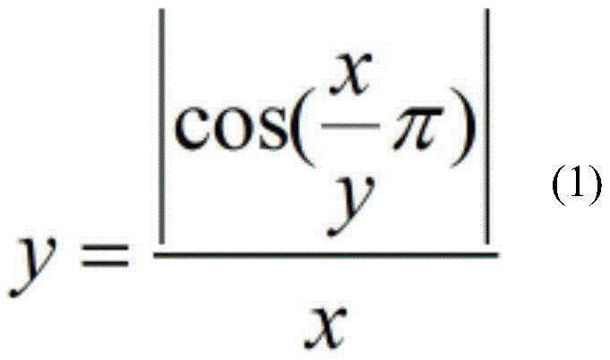
if the pressure value is within a first preset range and the pressure value is within a second preset range, judging whether the pressure value and the pressure value meet the following formula (1), and if so, generating accurate operation information; if not, judging whether the pressure value and the pressure value meet the following formula (2); if the formula (2) is not satisfied, generating the information of the pressure value which is increased or decreased;
where x represents a pressure value and y represents a pressure value.
An embodiment of the present invention further provides a medical injection control device, including:
the control module is used for controlling the needle head of the injector to be inserted into the body of the patient;
the depth detection module is used for detecting the depth of the needle head inserted into the body of the patient in real time;
the detection module is used for controlling a needle cylinder of the injector to press liquid medicine into the needle head if the depth is within a preset range of the specified position, and detecting the pressure value of the liquid medicine injected into the patient by the needle head in real time;
the tension generation module is used for generating a needle pulling tension value when the liquid medicine in the needle cylinder is injected by a set amount if the pressure is within a set range;
the control module is also used for controlling the manipulator to pull out the needle head according to the force corresponding to the needle pulling force value.
Optionally, the apparatus further comprises:
and the pressure detection module is used for detecting the pressure value applied to the patient by the needle head in real time in the process of inserting the needle head of the injector into the patient.
Optionally, the apparatus further comprises:
and the prompt processing module is used for generating prompt information according to the pressure value and the pressure value.
Optionally, the prompt information includes information on pressure for regulating the injection liquid medicine and information on pressure for regulating the needle head to apply to the patient; the prompt processing module is further configured to:
judging whether the pressure value is within a first preset range or not, and judging whether the pressure value is within a second preset range or not;
if the pressure value is not within the first preset range, generating pressure information for adjusting the injection liquid medicine;
if the pressure value is not in a second preset range; generating pressure information for adjusting the needle application to the patient.
Optionally, the prompt information includes operation accuracy information and information of increasing or decreasing the pressure value;
the prompt processing module is further configured to: if the pressure value is within a first preset range and the pressure value is within a second preset range, judging whether the pressure value and the pressure value meet the following formula (1), and if so, generating accurate operation information; if not, judging whether the pressure value and the pressure value meet the following formula (2); if the formula (2) is not satisfied, generating the information of the pressure value which is increased or decreased;
where x represents a pressure value and y represents a pressure value.
Compared with the prior art, the embodiment of the invention has the following beneficial effects:
the embodiment of the invention provides a medical injection control method and a medical injection control device, wherein the method comprises the following steps: controlling a needle head of the injector to be inserted into a patient, and detecting the depth of the needle head inserted into the patient in real time; if the depth is within the preset range of the designated position, controlling a needle cylinder of the injector to press liquid medicine into the needle head, and detecting the pressure value of the liquid medicine injected into the patient by the needle head in real time; if the pressure is within the set range, when the liquid medicine in the needle cylinder is injected by the set amount, a needle pulling force value is generated, and the manipulator is controlled to pull out the needle head according to the force corresponding to the needle pulling force value. The in-process that inserts the patient at the syringe needle, can give the pressure value that the patient applyed through first sensor real-time detection syringe needle to can indicate in real time and adjust the syringe needle and give the pressure value that the patient applyed, when adjusting the syringe needle and reduce painful sense for patient's nerve oppression, improve the accuracy and the injection effect of injection, make user experience good, improve the validity of treatment simultaneously, effectual.
Examples
The embodiment of the invention provides a medical injection control method which is applied to a robot. As shown in fig. 1, an embodiment of the present invention includes:
s101: the needle head of the injector is controlled to be inserted into the body of the patient, and the depth of the needle head inserted into the body of the patient is detected in real time.
S102: and if the depth is within the preset range of the designated position, controlling a needle cylinder of the injector to press liquid medicine into the needle head, and detecting the pressure value of the liquid medicine injected into the patient by the needle head in real time.
S103: if the pressure is within the set range, when the liquid medicine in the needle cylinder is injected by the set amount, a needle pulling force value is generated, and the manipulator is controlled to pull out the needle head according to the force corresponding to the needle pulling force value.
Through adopting above scheme, insert the internal in-process of patient at the syringe needle, can give the pressure value that the patient applyed through first sensor real-time detection syringe needle to can indicate in real time and adjust the syringe needle and give the pressure value that the patient applyed, when adjusting the syringe needle and reduce painful sense for patient's nerve oppression, improve the accuracy and the injection effect of injection, make user experience good, improve the validity of treatment simultaneously, effectual.
Optionally, the method further includes: during the process of inserting the needle of the syringe into the body of the patient, the pressure value applied to the patient by the needle is detected in real time. And generating prompt information according to the pressure value and the pressure value.
The prompt information comprises pressure information for adjusting the injection liquid medicine and pressure information for adjusting the needle head to apply to the patient; generating prompt information according to the pressure value and the pressure value, wherein the prompt information comprises: judging whether the pressure value is within a first preset range or not, and judging whether the pressure value is within a second preset range or not; if the pressure value is not within the first preset range, generating pressure information for adjusting the injection liquid medicine; if the pressure value is not in a second preset range; generating pressure information for adjusting the needle application to the patient.
Further, the prompt information comprises accurate operation information and information of the pressure value to be increased or decreased; generating prompt information according to the pressure value and the pressure value, and further comprising: if the pressure value is within a first preset range and the pressure value is within a second preset range, judging whether the pressure value and the pressure value meet the following formula (1), and if so, generating accurate operation information; if not, judging whether the pressure value and the pressure value meet the following formula (2); if the formula (2) is not satisfied, generating the information of the pressure value which is increased or decreased;
where x represents a pressure value and y represents a pressure value.
In an embodiment of the present invention, the injector may be a robotic injector 200 as shown in fig. 2. The robot injector 200 is used to inject a medicine into a patient, the robot injector 200 includes a syringe 210, a needle 220, and a first sensor 230; the syringe 210 includes an injection pressure generating part 211, a medicine liquid chamber 212, and a pressure detecting chamber 213, and the medicine liquid chamber 212 and the pressure detecting chamber 213 are partitioned by a fixed partition. The injection pressure generating portion 211 is disposed at an end of the medical fluid chamber 212 remote from the pressure detection chamber 213, and closes the medical fluid chamber 212. The first sensor is disposed in the pressure detection chamber 213. The needle 220 is connected to the first sensor, which is used to detect the pressure value applied to the patient when the needle 220 is inserted into the patient. The needle 220 communicates with the medicinal liquid chamber 212. The robotic injector 200 further includes a display for displaying the pressure value detected by the first sensor and displaying a prompt message to prompt an increase or decrease in the pressure value applied to the patient by the needle 220.
Through adopting above scheme, insert the internal in-process of patient at syringe needle 220, can give the pressure value that the patient applyed through first sensor real-time detection syringe needle 220 to can indicate in real time and adjust the pressure value that syringe needle 220 applyed for the patient, when adjusting syringe needle 220 and reduce painful sense for patient's nerve oppression, improve the accuracy and the injection effect of injection, make user experience good, improve the validity of treatment simultaneously, it is effectual.
Optionally, the needle 220 is provided with an injection channel, one end of the injection channel is open and arranged on the needle tip of the needle, such as a needle injection outlet 221 shown in fig. 1, and the other end of the injection channel is open and arranged on the side wall of the needle far away from the needle tip, such as a needle injection inlet 222 shown in fig. 1. The sidewall of the liquid medicine cavity 212 close to the partition is opened with a syringe injection port 214, the syringe injection port 214 is communicated with an opening (a needle injection inlet 222) on the sidewall of the needle 220 through a hose, that is, the needle 220 is communicated with the syringe 210 through a hose connecting the syringe injection port 214 and the needle injection inlet 222. A flexible tube sealingly connects syringe injection port 214 and needle injection inlet port 222.
The cross section of the needle tip of the needle 220 is circular, and the needle tip is observed to be circular when viewed from a straight line pointed by the needle tip of the needle 220 to the direction of the needle tip of the needle 220, that is, the needle injection outlet 221 is arranged at the center of the circular ring. The needle point in the prior art is wedge-shaped, and the injection outlet of the liquid medicine is arranged on the inclined plane of the wedge-shaped, namely on the side wall of the needle head, so that the inserting depth of the needle point of the needle head is greater than the depth of the needle head which can accurately inject the liquid medicine, which may cause inaccurate position of the liquid medicine injection or too much needle head which is inserted into a patient body for accurately injecting the liquid medicine, and bring damages to the physique and spirit of the patient. In the embodiment of the present invention in which the needle injection outlet 221 is disposed at the center of the cross-section of the needle tip, the radius of the circular ring of the cross-section of the needle 220 is continuously reduced from the needle injection inlet 222 to the length and direction of the needle injection outlet 221.
In order to reduce the pain of the patient caused by the injection, the robotic injector 200 further includes a second sensor disposed on an opening (needle injection inlet 222) formed on a sidewall of the needle 220, the second sensor being configured to detect the pressure of the liquid medicine injected from the needle 220.
In order to improve the accuracy of detecting the pressure of the liquid medicine injected from the needle 220, the second sensor is disposed on the opening (needle injection outlet 221) of the needle tip of the needle 220, and the second sensor is used for detecting the pressure of the liquid medicine injected from the needle.
The robotic injector 200 further comprises a processing device 240, the processing device 240 is disposed at a side of the injection pressure generating part 211 away from the medicinal liquid chamber 212, and the processing device 240 comprises a display screen 251; the second sensor is connected to the processing device 240, and the display screen 251 is configured to display the pressure value sent by the second sensor and the pressure value sent by the first sensor 230.
The processing device 240 further includes a processor, the processor is connected to the display screen 251, and the processor is configured to generate a prompt message according to the pressure value and the pressure value, and send the prompt message to the display screen 251, and the display screen 251 is further configured to display the prompt message.
Therefore, the pressure applied to the patient by the needle head 220, the insertion depth and the pressure of the injection liquid medicine can be adjusted according to the prompt information, and the treatment effect is improved. That is, the embodiment of the present invention may be implemented based on the robot injector 200 as follows: the processing device 240 controls the needle 220 of the injector to be inserted into the patient, and detects the depth of the needle 220 inserted into the patient in real time; if the depth is within the preset range of the designated position, the processing device 240 controls the syringe 210 of the robotic injector 200 to press the liquid medicine into the needle 220, and detects the pressure value of the liquid medicine injected into the patient by the needle 220 in real time through the missing two sensors 240. If the pressure is within the set range, when the injection of the liquid medicine in the syringe 210 is completed by the set amount, the processing device 240 generates a needle pulling force value, and controls the manipulator to pull out the needle 220 according to the force corresponding to the needle pulling force value. And the needle head 220 is pulled out according to the force corresponding to the needle pulling force value, so that no pain can be ensured in the needle pulling operation. During the insertion of the needle 220 of the robotic injector 200 into the patient, the amount of pressure applied by the needle 220 to the patient is detected in real time by the first sensor 230. The processor of the processing device 240 generates prompt information according to the pressure value and the pressure value.
So, can guarantee to control the injection operation accurately at every turn to insert syringe needle 220, pull out syringe needle 220 and inject liquid medicine according to painless pressure according to painless dynamics.
Further, the prompt message comprises information on the pressure for regulating the injection liquid and information on the pressure for regulating the needle to apply to the patient. Generating prompt information according to the pressure value and the pressure value, wherein the prompt information comprises the following steps: judging whether the pressure value is within a first preset range or not, and judging whether the pressure value is within a second preset range or not; if the pressure value is not within the first preset range, generating pressure information for adjusting the injection liquid medicine; if the pressure value is not in a second preset range; and generating pressure information for adjusting the needle to apply to the patient so as to adjust the pressure information applied to the patient by the needle in real time.
Optionally, the prompt information includes operation accuracy information and information of increasing or decreasing the pressure value; generating prompt information according to the pressure value and the pressure value, and further comprising: if the pressure value is within a first preset range and the pressure value is within a second preset range, judging whether the pressure value and the pressure value meet the following formula (1), and if so, generating accurate operation information; if not, judging whether the pressure value and the pressure value meet the following formula (2); if the formula (2) is not satisfied, generating the information of the pressure value which is increased or decreased;
where x represents a pressure value and y represents a pressure value.
So, can guarantee to control the injection operation accurately at every turn to insert syringe needle 220, pull out syringe needle 220 and inject liquid medicine according to painless pressure according to painless dynamics.
The prompt information further includes information of adjusting depth, and the processor of the processing device 240 is further configured to determine, according to the pressure value, a depth at which the needle extends into the patient, determine whether the depth meets a preset value, and if so, generate position accuracy information; otherwise, generating the information for adjusting the depth.
In an embodiment of the present invention, the second sensor may be an eleclean diffused silicon pressure sensor, a silicon pressure transmitter sensor for a silicon inlet diffusion for the beauty control (MEACON), a SLDYB-2088 pressure transmitter, or other hydraulic pressure sensor. The first sensor 230 is the medical robot sensor 100 shown in fig. 1. The medical robot sensor 100 includes a camera 110, a processor 120, a pressure probe 130, and a balloon 140. The pressure probe 130 is connected to the bladder 140 and the camera 110 is connected to the processor 120.
The pressure probe 130 is used to contact a subject to be measured to detect pressure, and the balloon 140 is used to detect the pressure detected by the pressure probe 130. In embodiments of the present invention, the untested object may be a robotic arm, a human body, an animal, and other objects, such as cement boards, cement floors, houses, electrical poles, computers, and the like. The camera 110 is configured to photograph the airbag 140, obtain an airbag image, and send the airbag image to the processor 120, and the processor 120 is configured to detect a deformation degree of the airbag according to the airbag image to detect the pressure. The processor 120 may be any type of processor having an image processing function, such as a dragon core 3A3000/383000, an Intel core i5-9300H, Intel core i5-9400H, Intel core i79750H, an Intel core i7-9850H, Intel core i9-9880H, and an Intel core i9-9980 HK.
Through adopting above scheme, through the deformation volume that detects gasbag 140 with pressure detection, because detect the gasbag image based on the processor, can accurately obtain the deformation volume of gasbag 140, so improve the accuracy that gasbag 140 received the external force, and then improve pressure detection's accuracy.
In the embodiment of the present invention, the processor 120 is further configured to control the camera 110 to capture an airbag image when receiving the capturing instruction. The processor 120 is configured to detect a deformation degree of the balloon 140 according to the balloon image, and detect the pressure by: the method comprises the steps of obtaining the outline of an air bag according to an air bag image, obtaining the deformation area of the air bag based on the outline of the air bag and the preset air bag outline, inputting the deformation area into a first pressure detection model, and taking the output of the first pressure detection model as the pressure value of a detected object. The camera 110 is disposed over the top of the airbag housing 150 to photograph the airbag 140.
At this time, the method of obtaining the outline of the balloon from the balloon image is as follows: and processing the airbag image by adopting a Canny operator, and extracting the outline of the airbag in the airbag image. Based on the outline of the air bag and the preset air bag outline, the obtained deformation area of the air bag is specifically as follows: and acquiring the area of the air bag in the area surrounded by the air bag outline and the preset area of the area surrounded by the preset air bag outline, and taking the difference between the area of the air bag and the preset area as the deformation area of the air bag. Inputting the deformation area into a first pressure detection model, and taking the output of the first pressure detection model as a pressure value received by a measured object, wherein the first pressure detection model is as follows:
wherein, F represents the pressure value received by the object to be measured, Delta S represents the deformation area of the air bag, G1 represents the weight of the pressure probe, G2 represents the weight of the air bag, and r represents the deformation coefficient of the air bag.
Optionally, the medical robot sensor further includes a capsule box 150 and a pressure movable plate 160, the capsule box 150 is cylindrical and barrel-shaped, and the top of the capsule box 150 is transparent. The airbag 140 is disposed in the bag case 150, and the pressure movable plate 160 is disposed in the bag case 150 for supporting the airbag 140. The pressure movable plate 160 may be movable in the axial direction of the bladder 150. One end of the pressure probe 130 is fixedly connected to the pressure-movable plate 160, and one end of the pressure probe 130 away from the pressure-movable plate 160 is used for detecting the pressure applied to the object to be measured. That is, the pressure probe 130 makes contact with the object to be measured, and the pressure applied to the object to be measured is transmitted to the pressure-movable plate 160 through the pressure probe 130, so that the pressure-movable plate 160 moves toward the top of the bladder 150, and the air bag 140 deforms under the pressure, thereby detecting the pressure applied to the object to be measured by detecting the deformation of the air bag 140. Among other things, the pressure movable plate 160 may be used to protect the airbag 140.
In this case, the processor 120 is configured to detect the deformation degree of the balloon 140 according to the balloon image, and further includes the following specific steps in order to detect the pressure: the deformation area is input into the second pressure detection model, the output of the second pressure detection model is used as the pressure value of the measured object, and the specific method can be as follows: the method comprises the steps of obtaining the outline of an air bag according to an air bag image, obtaining the deformation area of the air bag based on the outline of the air bag and the outline of a preset air bag, inputting the deformation area into a second pressure detection model, taking the output of the second pressure detection model as the pressure value of a measured object, and enabling the second pressure detection model to be:
wherein G3 represents the weight of the pressure plate.
In order to more accurately detect the pressure applied to the object to be measured, the medical robot sensor 100 further includes a gas pressure sensor 170, and the gas pressure sensor 170 is connected to the processor 120. An air pressure sensor 170 is disposed within bladder chamber 150 for sensing the pressure within bladder chamber 150 and transmitting the pressure within bladder chamber 150 to processor 120. The processor 120 is further configured to determine a pressure value to which the object is subjected based on the pressure within the bladder housing 150 and the deformation area of the bladder 140. The processor 120 determines the pressure value to which the measured object is subjected according to the pressure in the bladder box 150 and the deformation area of the bladder, and specifically includes: inputting the pressure and the deformation area of the air bag into a third pressure detection model, taking the output of the third pressure detection model as the pressure value of the measured object, wherein the third pressure detection model is as follows:
s2 represents a projected area of the
airbag 140 on the top of the
bag box 150 after the deformation of the
airbag 140, where a is 0.3, b is 0.7, P1 represents pressure, and P represents atmospheric pressure. That is, the pressure variation obtained by detecting the variation of the pressure in the
bladder box 150 and the pressure value obtained by photographing the deformation value of the bladder and according to the deformation coefficient of the bladder are weighted, and the corresponding error value is subtracted, and the weights of the
pressure probe 130, the
bladder 140 and the pressure
movable plate 150 in the
medical robot sensor 100 are added, so that the pressure value to which the object to be measured is subjected is finally obtained, and the accuracy of pressure detection is improved. In the interim, the pressure variation detected from the variation of the pressure in the
bladder box 150 is (P1-P) × 2 × S2, and the pressure value obtained from the deformation coefficient of the bladder is (2 × Δ S × r), and the corresponding error value is (P) Δ S × r
In the middle, e
rThe index representing r, e is a natural index, a base of natural logarithm, sometimes referred to as the Euler's Number, is an infinite acyclic fractional Number having a value of about: 2.71828182845904523536.
the air pressure sensor 170 may be a CS100 air pressure sensor, an air pressure sensor TP-4310, or the like.
In order to improve the accuracy of detecting the deformation degree of the airbag 140, after the processor 120 receives the shooting instruction, the camera 110 is controlled to shoot a plurality of airbag images, that is, there are a plurality of airbag images, the shooting angles of the airbag images are the same (same camera, same angle), the shooting times of the airbag images are adjacent, and then the processor 120 obtains the outline of the airbag according to the airbag images, including: identifying the air bag in each air bag image, obtaining the edge of one air bag in each air bag image, and obtaining the edges of a plurality of air bags corresponding to the plurality of air bag images. Then randomly extracting the edge of one of the edges of the multiple airbags as a target contour, and calculating the distances from the edges of the rest airbags to the target contour under the same visual angle, wherein the edge of each rest airbag corresponds to one distance, and the edges of the multiple airbags correspond to multiple distances. Then obtaining the average distance of the distances and obtaining the average size of the outline formed by the edges of the airbags; i.e. the average of the sizes of the edges of the plurality of air bags. And finally, obtaining an average contour based on the average size, and setting the average contour at the position of the target contour translated by the average distance to obtain the contour of the air bag. Thus, the accuracy of the contour of the air bag after the air bag deforms under the pressure of the external force is high.
In one embodiment, the pressure movable plate 160 is provided with a plurality of vent holes to maintain the pressure inside the bladder 150 in balance with the pressure outside the bladder 150 when the bladder 140 is deformed. In another embodiment, the pressure-movable plate 160 is movably connected to the bag box 150 in a sealing manner, so as to detect the pressure inside the bag box 150 and thus the magnitude of the pressure applied by the pressure-movable plate 150 to the airbag 140, and thus the pressure value applied to the object to be detected. In the embodiment of the invention, the pressure applied to the detected object is detected according to the principle of acting force and reacting force.
Optionally, the medical robot sensor 100 further includes a semicircular camera cover 180. The shooting pot 180 has a diameter equal to that of the top of the capsule 150, and the camera 110 is disposed on the shooting pot 180. In order to obtain the balloon image from a plurality of positions and to improve the accuracy of obtaining the contour of the balloon and thus the accurate deformation area by the processor 120, the medical robot sensor 100 includes a plurality of cameras 110, i.e., a plurality of cameras 110, and the plurality of cameras 110 are connected to the processor. A plurality of shooting holes are uniformly formed on the shooting cover 180, and the camera 110 is disposed on the shooting holes to shoot the airbag 140 from a plurality of directions. In the embodiment of the present invention, the camera 110 may be a black-and-white night vision camera, an RGB camera, a charge-coupled device (CCD) camera, a Complementary Metal Oxide Semiconductor (CMOS) camera, or the like.
The camera system comprises a plurality of cameras, a plurality of cameras and a plurality of cameras, wherein the cameras shoot airbag images at a plurality of angles, each camera shoots a plurality of airbag images, the shooting time of the airbag images shot by each camera is adjacent, the airbag images shot by each camera correspond to the outline of an airbag in the position where the camera is located, and the cameras correspond to the outlines of the airbags in a plurality of positions. Obtaining a deformation area of the airbag based on the outline of the airbag and a preset airbag outline, comprising: setting outlines of airbags in multiple directions in the same empty image to obtain an airbag superposed image, wherein the size of the airbag superposed image is the same as that of the airbag image; obtaining a plurality of intersection positions of the outline of the airbag at a plurality of orientations; connecting the plurality of intersecting positions to obtain a first contour; fitting based on the first contour to obtain a second contour, wherein the second contour represents the projection of the airbag on the top of the airbag box after the airbag deforms; and taking the difference between the area of the second contour and the area of the preset air bag contour as the deformation area of the air bag. Therefore, errors existing in the deformation area of the airbag during observation and shooting at each visual angle are considered, the deformation area of the airbag obtained at last is combined with the deformation area of the airbag during observation and shooting at a plurality of visual angles, the accuracy of obtaining the deformation area of the airbag is improved, and the accuracy of detecting pressure is further improved.
In the embodiment of the present invention, the
airbag 140 is made of a deformable transparent material, the deformation of the
airbag 140 has recoverability, and the difference between the deformation projection area of the
airbag 140 and the external force applied thereto satisfies the following formula:
here, F1 represents an external force to which the
airbag 140 is subjected. Wherein the deformation coefficient r of the airbag satisfies the following formula:
wherein S1 represents the area of the preset balloon profile. Δ S represents a deformation area of the airbag.
Alternatively, bladder 140 is made of a metal mixed transparent rubber having a composition comprising 30% powdered shape memory alloy, 10% powdered magnet, and 60% rubber. Through evenly mixing the powdery shape memory alloy, the powdery magnet and the rubber, the manufactured air bag 140 has the shape memory performance, and the toughness and the ductility of the rubber are improved under the action of the magic magnet, so that the reusability of the medical robot sensor 100 is improved, the service life of the medical robot sensor 100 is prolonged, and the accuracy of pressure detection is improved.
In order to protect the camera 110, the medical robot sensor 100 further includes a semicircular protective cover 190. The radius of the protective cover is greater than the sum of the radius of the camera cover 180 and the height of the camera head 110 so that the camera cover 180 and the camera head 110 can be contained within the protective cover 190. The protective cover 190 is disposed outside the camera cover 180, and forms a cavity with a cross section of an annular shape with the camera cover 180 to protect the camera 110.
Optionally, the processor 120 is disposed on a side of the protective cover 190 away from the shoot cover 180. The protective cover 190 is provided with a plurality of wire holes through which connecting wires pass to connect the camera 110 and the processor 120.
Wherein, one side that the safety cover 190 kept away from and shoot cover 180 is equipped with first installation department, and pressure detection chamber 213 inner wall is equipped with the second installation department, and first installation department can be dismantled firm the connection with the second installation department to make medical robot sensor 100 install in pressure detection chamber 213.
In order to obtain the contour of the air bag accurately, the air bag 140 is closed, and the air bag 140 is filled with red gas. Alternatively, when the external force applied to the airbag 140 is zero, the airbag 140 is a spherical bag, and the projection of the airbag 140 and the red gas in the airbag on the top of the bag box 150 is a circle.
Wherein, the end of the needle 220 away from the needle tip is detachably and stably connected to the end of the pressure probe 130 away from the pressure movable plate 160, and the pressure value applied by the needle 220 to the patient is calculated as follows:
where G4 represents the weight of the needle 220 and G5 represents the weight of the hose.
Wherein the processor 120 is connected to the processing device 240.
As shown in fig. 3, the inner wall of the bag box 150 is opened with a sliding groove 151, and the sliding groove 151 extends along the axial direction of the bag box 150. The pressure movable plate 160 is provided with a protrusion 161, and the protrusion 161 is snapped into the sliding groove 151 and can slide along the sliding groove 151. The cross section of the sliding groove 151 is a three-quarter circular arc. The sliding groove 151 is provided with a plurality of ball grooves 152, and the ball grooves 152 are provided with a plurality of balls 153.
The cross-section of the ball groove 152 is a three-quarter circular arc, and the circular arc radius of the ball groove 152 is less than or equal to one tenth of the circular arc radius of the sliding groove 151. The ball 153 is circular, and the radius of the ball 153 is smaller than the arc radius of the ball groove 152 and is greater than or equal to three-quarters of the arc radius of the ball groove 152.
The protrusion 161 is a sphere, and the diameter of the protrusion 161 is larger than or three-quarters of the double radius of the arc of the sliding groove 151 and smaller than one fifth of the radius of the arc.
Lubricating oil is applied or injected to the sliding groove 151, the protrusion 161, the ball groove 152, and the ball 153 to reduce friction between the bladder 150 and the pressure movable plate 160, thereby improving accuracy of pressure detection.
In order to keep the pressure movable plate 160 parallel to the top of the bag box 150 and to ensure the stability of the pressure movable plate 160, three sliding grooves 151 are uniformly formed on the inner wall of the bag box 150, and the sliding grooves 151 are connected to form an isosceles triangle. There are three protrusions 161 correspondingly.
The medical robot sensor 100 and the second sensor are connected to the processing device 240, and the pressure value detected by the sensors are transmitted to the processing device 240.
The embodiment of the present application also correspondingly provides an executing main body for executing the above steps, and the executing main body may be the medical injection control device 300 in fig. 4. Referring to fig. 4, the apparatus includes:
a control module 310 for controlling the insertion of the needle of the syringe into the patient;
a depth detection module 320 for detecting the depth of the needle inserted into the patient in real time;
the detection module 330 is configured to control a syringe of the injector to press liquid medicine into the needle head if the depth is within a preset range of the specified position, and detect a pressure value of the needle head injecting the liquid medicine into the patient in real time;
the tension generating module 340 is configured to generate a needle pulling tension value when the liquid medicine in the needle cylinder is injected by a set amount if the pressure is within the set range;
the control module is also used for controlling the manipulator to pull out the needle head according to the force corresponding to the needle pulling force value.
And the pressure detection module is used for detecting the pressure value applied to the patient by the needle head in real time in the process of inserting the needle head of the injector into the patient.
And the prompt processing module is used for generating prompt information according to the pressure value and the pressure value.
The prompt information comprises pressure information for adjusting the injection liquid medicine and pressure information for adjusting the needle head to apply to the patient; the prompt processing module is further configured to:
judging whether the pressure value is within a first preset range or not, and judging whether the pressure value is within a second preset range or not;
if the pressure value is not within the first preset range, generating pressure information for adjusting the injection liquid medicine;
if the pressure value is not in a second preset range; generating pressure information for adjusting the needle application to the patient.
The prompt information comprises accurate operation information and information of the pressure value to be increased or the pressure value to be decreased;
the prompt processing module is further configured to: if the pressure value is within a first preset range and the pressure value is within a second preset range, judging whether the pressure value and the pressure value meet the following formula (1), and if so, generating accurate operation information; if not, judging whether the pressure value and the pressure value meet the following formula (2); if the formula (2) is not satisfied, generating the information of the pressure value which is increased or decreased;
where x represents a pressure value and y represents a pressure value.
With regard to the apparatus in the above-described embodiment, the specific manner in which each module performs the operation has been described in detail in the embodiment related to the method, and will not be elaborated here.