Disclosure of Invention
The embodiment of the invention provides a generator and a wind generating set, wherein the generator can ensure the uniformity of an air gap between a rotor and a stator, and further can ensure the generating benefit of the wind generating set.
An embodiment of the present invention provides a generator, including: the shafting structure comprises a rotating shaft and a fixed shaft which are coaxially arranged and rotationally connected; the rotor is connected to the rotating shaft; the stator is connected with the fixed shaft, arranged facing the rotor and provided with an air gap between the rotor and the stator in the radial direction of the shafting structure; the bearing group is radially supported between the rotor and the stator, the bearing group comprises more than two adjusting bearings which are arranged at intervals along the axial direction of the shafting structure, and the rotor and the stator are rotationally connected through the more than two adjusting bearings.
According to an aspect of the embodiment of the present invention, at least one of the two or more adjusting bearings includes a bearing bracket and a friction member disposed on the bearing bracket, the friction member is movably connected to the bearing bracket, the bearing bracket is disposed around the shafting structure and is fixedly or detachably connected to one of the rotor and the stator, and the friction member abuts against the other of the rotor and the stator.
According to an aspect of the embodiment of the present invention, the adjusting bearing is a sliding bearing, the friction member is a sleeve movably connected with the bearing support, and the friction member abuts against and is in sliding fit with the other one of the rotor and the stator.
According to an aspect of the embodiment of the present invention, the adjusting bearing is a rolling bearing, the friction member is a plurality of rolling bodies spaced apart from each other on the bearing bracket, the plurality of rolling bodies are rotatably connected to the bearing bracket, and the friction member is abutted against and in rolling engagement with the other of the rotor and the stator.
According to one aspect of the embodiment of the invention, the bearing support is a closed annular structure body, and a plurality of rolling bodies are uniformly arranged along the circumferential direction of the shafting structure; or, the bearing support is a sectional type annular structure body, the bearing support comprises more than two arc-shaped units, the more than two arc-shaped units are arranged at intervals or are sequentially spliced, and each arc-shaped unit is rotatably connected with at least one rolling body.
According to one aspect of the embodiment of the invention, the cross section of the bearing support in the circumferential direction of the shafting structure is in a T shape, the bearing support comprises a fixing plate and an installation plate which are arranged in an intersecting manner and connected with each other, a plurality of connecting holes are arranged on the fixing plate at intervals in the circumferential direction, the bearing support is fixedly or detachably connected with one of the rotor and the stator through the fixing plate, and the rolling body is rotatably arranged on the installation plate.
According to an aspect of the embodiment of the present invention, the adjusting bearing further includes a retainer, the retainer is provided with a plurality of through holes, the number of the through holes is greater than or equal to the number of the rolling bodies, the retainer is fastened to the bearing support, each rolling body is located between the bearing support and the retainer, and each rolling body at least partially protrudes from the through hole opposite to the rolling body.
According to one aspect of an embodiment of the invention, the holder is of a closed annular groove structure; or the retainer is of a sectional type annular groove body structure and comprises more than two arc groove body units which are arranged at intervals or spliced in sequence.
According to an aspect of the embodiment of the present invention, the rotor or the stator abutting against the friction member is provided with a limit groove, the limit groove is an annular groove arranged around the shafting structure, and at least a part of the friction member extends into the limit groove and is in sliding or rolling fit with a groove wall of the limit groove.
According to one aspect of the embodiment of the invention, the limit groove is directly arranged on the rotor or the stator which is abutted against and movably connected with the friction piece; or, the surface of the rotor or the stator, which is abutted against the friction piece, facing the friction piece is provided with an annular structure body, and the limit groove is arranged on the annular structure body.
According to an aspect of the embodiment of the present invention, the number of the adjustment bearings is two, wherein one of the adjustment bearings is located at the same end of the rotor and the stator in the axial direction, and the other adjustment bearing is located at the other end of the rotor and the stator in the axial direction.
According to an aspect of the embodiment of the present invention, the generator further includes an elastic connection member, the elastic connection member includes a plurality of elastic couplings uniformly arranged along a circumferential direction of the shafting structure; one end of each elastic coupling is hinged with the rotor ball, and the other end of each elastic coupling is hinged with the rotating shaft ball; alternatively, one end of each elastic coupling is hinged to the stator ball and the other end is hinged to the fixed shaft ball.
According to an aspect of an embodiment of the present invention, a maintenance window is provided on the stator or the rotor, the maintenance window being disposed opposite to the adjustment bearing.
According to an aspect of an embodiment of the present invention, the rotor has a rotor holder and magnetic steel connected to each other, the rotor is connected to the rotating shaft through the rotor holder, the stator has a stator holder and an induction coil connected to each other, the stator is connected to the fixed shaft through the stator holder, one of the rotor holder and the stator holder includes an annular plate and at least one side plate arranged around the shafting structure; the other one of the rotor support and the stator support comprises a connecting plate extending along the radial direction and a U-shaped plate surrounding the shafting structure and connected with the connecting plate, the U-shaped opening of the U-shaped plate faces the annular plate, the U-shaped plate and the annular plate form an annular cavity together, the magnetic steel and the induction coil are positioned in the annular cavity, and an air gap is formed between the magnetic steel and the induction coil; at least one adjusting bearing is connected to each end of the U-shaped plate in the axial direction, and the adjusting bearings abut against the annular plate.
According to another aspect of the embodiment of the invention, a wind generating set is provided, which comprises an impeller, a cabin and the generator, wherein a rotating shaft is connected with the impeller, and a fixed shaft is connected with a base of the cabin.
According to the generator and the wind generating set provided by the embodiment of the invention, the generator comprises a shafting structure, a rotor, a stator and a bearing set, the shafting structure comprises a rotating shaft and a fixed shaft which are rotatably connected, the rotor is connected with the rotating shaft, the stator is connected with the fixed shaft, the stator is arranged facing the rotor, and an air gap is formed between the stator and the rotor in the radial direction of the shafting structure. Because the bearing group radially supports between rotor and stator, the bearing group includes the more than two regulation bearings that set up along the mutual interval of axial of shafting structure, rotor and stator rotate through the more than two regulation bearings and connect, make rotor and stator under the effect of external load, can keep the relative radial synchronous deformation of rotor and stator, thereby guarantee the homogeneity of air gap between rotor, the stator, can effectually avoid rotor and stator to take place the fish tail when relative rotation, phenomenons such as card is dead, guarantee wind generating set's power generation benefit.
Detailed Description
Features and exemplary embodiments of various aspects of the present invention will be described in detail below. In the following detailed description, numerous specific details are set forth in order to provide a thorough understanding of the present invention. It will be apparent, however, to one skilled in the art that the present invention may be practiced without some of these specific details. The following description of the embodiments is merely intended to provide a better understanding of the present invention by illustrating examples of the present invention. In the drawings and the following description, at least some well-known structures and techniques have not been shown in detail in order to avoid unnecessarily obscuring the present invention; also, the dimensions of some of the structures may be exaggerated for clarity. Furthermore, the described features, structures, or characteristics may be combined in any suitable manner in one or more embodiments.
The following description is given with the directional terms shown in the drawings, and is not intended to limit the specific structure of the generator and the wind turbine generator system of the present invention. In the description of the present invention, it should also be noted that, unless otherwise explicitly specified or limited, the terms "mounted" and "connected" are to be interpreted broadly, e.g., as either a fixed connection, a removable connection, or an integral connection; can be directly connected or indirectly connected. The specific meaning of the above terms in the present invention can be understood as appropriate to those of ordinary skill in the art.
The generator provided by the embodiment of the invention can be used for generating electricity. Especially in the technical field of wind power, the wind driven generator set can be used for generating electricity by utilizing wind energy. The following embodiments of the present invention are described with reference to the generator only being used in a wind turbine generator system, but the generator of the embodiments of the present invention is not limited to the following embodiments, and may be mounted in and protected by power generation equipment in other fields.
For a better understanding of the present invention, a generator and a wind turbine generator set according to an embodiment of the present invention will be described in detail below with reference to fig. 4 to 14.
Referring to fig. 4, fig. 4 shows a schematic structural diagram of a wind turbine generator system according to an embodiment of the present invention, which mainly includes a tower 400, a nacelle 300, a generator 100, and an impeller 200, wherein the nacelle 300 is disposed at a top end of the tower 400, and the generator 100 is disposed in the nacelle 300, and may be located inside the nacelle 300, or of course, may be located outside the nacelle 300. The impeller 200 includes a hub 201 and two or more blades 202 respectively connected to the hub 201, the generator 100 is connected to the hub 201 and fixed to a base of the nacelle 300, and the blades 202 drive the hub 201 to rotate under the action of wind load, thereby realizing power generation of the generator 100.
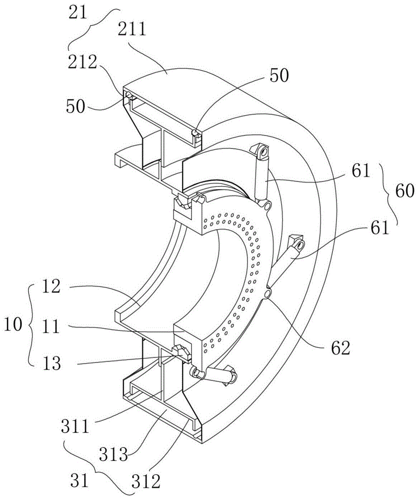
Referring to fig. 5 to 8 together, fig. 5 is a partial structural schematic view of a wind turbine generator system according to an embodiment of the present invention, fig. 6 is an isometric view of a generator 100 according to an embodiment of the present invention, fig. 7 is a partial sectional view of the generator 100 according to an embodiment of the present invention, and fig. 8 is a half sectional view of a part of structural members of the generator 100 according to an embodiment of the present invention.
In some optional embodiments, the generator 100 of the wind turbine generator system provided by the embodiment of the present invention includes a shafting structure 10, a rotor 20, a stator 30, and a bearing set, where the shafting structure 10 includes a rotating shaft 11 and a fixed shaft 12 that are coaxially disposed and rotationally connected. The rotor 20 is connected to the rotating shaft 11, the stator 30 is connected to the fixed shaft 12, and the stator 30 is disposed facing the rotor 20 and forms an air gap 40 with the rotor 20 in the radial direction Y of the shafting structure 10. The bearing set is supported between the rotor 20 and the stator 30 in the radial direction Y, the bearing set includes two or more adjusting bearings 50 arranged at intervals along the axial direction X of the shafting structure 10, and the rotor 20 and the stator 30 are rotatably connected through the two or more adjusting bearings 50.
The generator 100 provided by the embodiment of the invention can ensure the uniformity of the air gap 40 between the rotor 20 and the stator 30, and further can ensure the power generation benefit of the wind generating set.
Specifically, the rotating shaft 11 and the fixed shaft 12 are respectively a kit, in some alternative examples, the rotating shaft 11 partially extends into the fixed shaft 12 and is disposed coaxially with the fixed shaft 12, a rotating support 13 is disposed between the rotating shaft 11 and the fixed shaft 12, the rotating support 13 may be a bearing structure, the number of the rotating supports 13 may be one, and a double-row rolling bearing may be adopted. The inner ring of the rotary support 13 is connected with the rotating shaft 11, the outer ring of the rotary support is connected with the fixed shaft 12, an end flange is arranged at one end of the rotating shaft 11 far away from the fixed shaft 12, and the whole generator 100 can be fixedly connected with the hub 201 of the impeller 200 through the end flange on the rotating shaft 11. And an end flange is also arranged at one end of the fixed shaft 12 far away from the rotating shaft 11, and the whole generator 100 can be fixedly connected with the base of the nacelle 300 through the end flange on the fixed shaft 12.
With continued reference to fig. 5 to 8, in some alternative examples, the rotor 20 may have a rotor bracket 21 and a magnetic steel 22 connected to each other, the rotor 20 is connected to the rotating shaft 11 through the rotor bracket 21, the rotor bracket 21 may be directly connected to the rotating shaft 11, and of course, the rotor bracket 21 may be indirectly connected to the rotating shaft 11 through other structural members. The rotor bracket 21 includes an annular plate 211 disposed around the shafting structure 10 and two side plates 212, and the two side plates 212 are disposed symmetrically with respect to each other in the axial direction X of the shafting structure 10. One of the side plates 212 is connected to one end of the annular plate 211 in the axial direction X, and the other side plate 212 is connected to the other end of the annular plate 211 in the axial direction X. The two side plates 212 extend towards the shafting structure 10, and a gap is left between the two side plates and the fixed shaft 12 of the shafting structure 10. The side plate 212 may be a rigid member, but in some other examples, the side plate 212 may also be a flexible member, such as a soft belt.
Alternatively, the stator 30 may have a stator holder 31 and an induction coil 32 connected to each other, and the stator 30 is connected to the fixed shaft 12 through the stator holder 31. Stator support 31 includes connecting plate 311 and the U-shaped plate 312 that encircles shafting structure 10 and interconnect of connecting plate 311 that extends along the radial Y of shafting structure 10, and U-shaped opening 313 of U-shaped plate 312 is towards annular plate 211, forms the annular chamber jointly between U-shaped plate 312 and the annular plate 211, and magnet steel 22 and induction coil 32 are located the annular chamber, and air gap 40 forms between magnet steel 22 and induction coil 32, and connecting plate 311 is connected with dead axle 12 to support stator 30 in the periphery of dead axle 12 wholly.
In some alternative embodiments, the generator 100 provided in the embodiments of the present invention may include two adjusting bearings 50 in the bearing set, where one adjusting bearing 50 is located at the same end of the rotor 20 and the stator 30 in the axial direction X, and the other adjusting bearing 50 is located at the other end of the rotor 20 and the stator 30 in the axial direction X.
When two adjusting bearings 50 are specifically arranged, one of the adjusting bearings 50 is specifically connected to one end of the U-shaped plate 312 of the stator bracket 31 in the axial direction X of the shafting structure 10, and the other adjusting bearing 50 is specifically connected to the other end of the U-shaped plate 312 in the axial direction X of the shafting structure 10.
Each adjusting bearing 50 can adopt different structural forms, at least one adjusting bearing 50 comprises a bearing support 51 and a friction piece 52 arranged on the bearing support 51, the friction piece 52 is movably connected with the bearing support 51, the bearing support 51 is arranged around the shafting structure 10 and is fixedly or detachably connected with one of the rotor 20 and the stator 30, and the friction piece 52 is abutted against the other one of the rotor 20 and the stator 30. As some alternative embodiments, the bearing bracket 51 and the U-shaped plate 312 of the stator 30 may be welded, or may be detachably connected by a fastener such as a bolt.
Referring to fig. 5 to 9, fig. 9 shows an enlarged view of a in fig. 7, the bearing bracket 51 may take various forms, and in some alternative embodiments, the cross section of the bearing bracket 51 in the circumferential direction Z of the shafting structure 10 is "T". The bearing support 51 comprises a fixing plate 511 and a mounting plate 512 which are arranged in an intersecting manner and connected with each other, a plurality of connecting holes 513 are arranged on the fixing plate 511 at intervals along the circumferential direction Z, the bearing support 51 is detachably connected with the U-shaped plate 312 of the stator 30 through the fixing plate 511 by fasteners such as bolts, and a receiving groove is arranged on the surface of the mounting plate 512 far away from the fixing plate 511 and used for mounting the friction element 52.
The adjusting bearing 50 may take various bearing structures, and in some alternative examples, the adjusting bearing 50 may be a rolling bearing, the friction member 52 may be a plurality of rolling bodies 521 spaced apart from each other on the bearing bracket 51, the plurality of rolling bodies 521 are rotatably connected to the bearing bracket 51, and in particular, the rolling bodies 521 may be located in the receiving groove of the mounting plate 512.
In some optional examples, the rolling elements 521 may be spherical structures, and in order to better define the positions of the rolling elements 521 on the mounting plate 512, optionally, the adjusting bearing 50 further includes a retainer 53, the retainer 53 is provided with a plurality of through holes, the number of the through holes is greater than or equal to the number of the rolling elements 521, the retainer 53 is fastened to the bearing bracket 51, each rolling element 521 is located between the bearing bracket 51 and the retainer 53, and each rolling element 521 at least partially protrudes out of the through hole opposite to itself. The part of the rolling element 521 protruding out of the retainer 53 and the annular plate 211 of the rotor bracket 21 are abutted against each other and are in rolling fit, the retainer 53 and the bearing bracket 51 can be processed in a split manner and are connected and fixed in a welding or clamping manner, a fastener connection manner and the like, and of course, the retainer 53 and the bearing bracket 51 can be in an integrated structure.
The generator 100 provided by the embodiment of the invention is the generator 100 in the form of the outer rotor 20, and when the generator is applied to a wind generating set, the generator is connected with the hub 201 through the rotating shaft 11 and is connected with the base of the engine room 300 through the fixed shaft 12. When the blades 202 drive the hub 201 and the rotating shaft 11 to rotate under the action of wind energy, the rotor 20 on the rotating shaft 11 can rotate relative to the stator 30 on the fixed shaft 12, so that the magnetic steel 22 of the rotor 20 and the induction coil 32 of the stator 30 perform magnetic line cutting motion, magnetic induction current is generated, power is generated, and the power generation requirement of the wind generating set is met.
Meanwhile, since the bearing set is supported between the rotor 20 and the stator 30 in the radial direction Y of the shafting structure 10, the bearing set includes two adjusting bearings 50 arranged at intervals along the axial direction X of the shafting structure 10. The rotor 20 and the stator 30 are rotatably connected through the two adjusting bearings 50, so that the rotor 20 and the stator 30 can keep relative radial Y synchronous deformation of the rotor 20 and the stator 30 under the action of an external load, such as wind load bending moment of the impeller 200 or gravity load, uniformity of an air gap 40 between the rotor 20 and the stator 30 is ensured, phenomena of scratching, clamping and the like when the rotor 20 and the stator 30 rotate relatively are effectively avoided, and power generation benefit of the wind generating set is further ensured.
With continued reference to fig. 5 to 9, the bearing bracket 51 is a segmented annular structure, the bearing bracket 51 includes more than two arc units 51a, the more than two arc units 51a are disposed at intervals, and each arc unit 51a is rotatably connected with at least one rolling element 521. The number of the arc units 51a is not limited to a specific number, and may be specifically limited according to the size of the generator 100 itself.
With the above arrangement, the rotor 20 and the stator 30 can be deformed in synchronization with each other in the radial direction Y by the external load, thereby maintaining the relative radial deformation of the rotor 20 and the stator 30. Meanwhile, the bearing support 51 is a segmented annular structure, and more than two arc-shaped units 51a are arranged at intervals, so that the overall manufacturing cost of the generator 100 can be effectively reduced, and the installation and replacement of the adjusting bearing 50 are facilitated.
More importantly, the regulating bearing 50 is limited to the structural form, so that the requirement of the land machine set on the development of high power can be met, and the reasons are as follows: the variation of the air gap 40 of the generator 100 under bending moment loading is proportional to the width of the generator 100 (or the width between the stator 30 and the rotor 20), i.e. the wider the generator 100, the greater the variation of the air gap 40. As high power units are developed, it is necessary to require the diameter of the generator 100 to be increased or the width of the generator 100 to be increased, but the diameter of the generator 100 is limited by transportation size limitation (the diameter of the generator 100 of a land unit cannot be larger than 5m, otherwise, the generator 100 cannot pass through a tunnel or a bridge during transportation), so that the width of the generator 100 can only be increased. When the width of the generator 100 is increased, in order to keep the variation of the air gap 40 under the bending moment load from increasing, the bending stiffness of the rotating shaft 11 and the rotating support 13 and the manufacturing accuracy of the stator 30 and the rotor 20 must be increased, thereby greatly increasing the manufacturing cost of the generator 100. According to the analysis of the manufacturing cost data of the generator 100 in the past, the manufacturing cost of the generator 100 is proportional to the square of the width of the generator 100. Therefore, the prior art generator 100 has not been able to meet the development requirements of land based units to high power.
In the generator 100 provided by the embodiment of the present invention, the bearing set is disposed between the rotor 20 and the stator 30, and the bearing bracket 51 defining the adjusting bearing 50 included in the bearing set adopts a segmented annular structure, so that the width of the generator 100 can be greatly reduced, the problem in the prior art that the air gap 40 between the rotor 20 and the stator 30 is not uniform due to the deformation and manufacturing error of the rotor 20 under the load action caused by the increase of the width of the generator 100 and the increase of the power, is effectively solved, the manufacturing costs of the rotor 20 and the stator 30 are reduced, the bottleneck of limited transportation of the high power generator 100 is overcome, and the development of the land ultra-large wind driven generator 100 becomes possible.
When the bearing support 51 adopts a sectional annular structure body, correspondingly, the retainer 53 can also be in a sectional annular groove body structure, the retainer 53 comprises more than two arc groove body units 53a, the more than two arc groove body units 53a can be arranged at intervals, the number of the arc groove body units 53a can be the same as that of the arc units 51a of the bearing support 51 and can be arranged in a one-to-one correspondence manner, the limiting effect on the rolling bodies 521 can be better met, and meanwhile, the cost and the transportation requirement of the generator 100 can be guaranteed.
Of course, the above-mentioned form of the bearing bracket 51 of the generator 100 provided by the above-mentioned embodiments of the present invention is only an optional implementation manner, in some other examples, when the power of the unit is small and the transportation of the generator 100 is not limited, the two or more arc-shaped units 51a of the bearing bracket 51 of each adjusting bearing 50 may also be sequentially spliced along the circumferential direction Z of the shafting structure 10, or the bearing bracket 51 may also be a closed annular structure, and the plurality of rolling elements 521 are uniformly arranged along the circumferential direction Z of the shafting structure 10, which may be specifically selected according to the cost budget, the transportation requirement, and other conditions of the generator 100.
Accordingly, the form of the retainer 53 of the generator 100 provided by the above embodiments of the present invention is only an optional implementation manner, and in some other examples, the retainer 53 may also be a closed annular groove structure, or the retainer 53 still has a segmented annular groove structure, and two or more arc groove units 53a thereof are sequentially spliced, and on the basis of satisfying the limiting effect on the rolling elements 521, the form may be selected according to the conditions of the cost budget, the transportation requirements, and the like of the generator 100.
Referring to fig. 9, as an alternative embodiment, the rotor 20 abutting against the friction member 52 is provided with a limiting groove 23, the limiting groove 23 is an annular groove disposed around the shafting structure 10, and at least a portion of the friction member 52 extends into the limiting groove 23 and is in rolling fit with the limiting groove 23. Through setting up spacing groove 23, can carry on spacingly to rotor 20, prevent that rotor 20 from drunkenness on the axial X of shafting structure 10, better satisfying the electricity generation requirement of generator 100.
In specific implementation, the limiting groove 23 may be directly disposed on the rotor 20 abutting against the friction member 52, specifically, may be directly disposed on the annular plate 211 of the rotor support 21, and of course, in some other examples, in order to meet the rigidity requirement of the rotor support 21 or when the thickness of the annular plate 211 of the rotor support 21 is not enough to meet the opening requirement of the limiting groove 23, optionally, an annular structure is disposed on the surface of the rotor 20 abutting against the friction member 52 facing the friction member 52, and the limiting groove 23 is disposed on the annular structure, which can also meet the limiting requirement on the rotor 20. By arranging the limiting groove 23, lubricating grease or lubricating oil can be regularly coated in the limiting groove 23, friction between the friction piece 52 and the rotor support 21 is effectively prevented from generating heat, and abrasion of the friction piece 52 and the rotor support 21 is further reduced.
Referring to fig. 5 to 9, as an alternative embodiment, the generator 100 according to the embodiment of the present invention further includes an elastic connecting member 60, wherein the elastic connecting member 60 includes a plurality of elastic couplings 61 uniformly arranged along the circumferential direction Z of the shafting structure 10. One end of each elastic coupling 61 is hinged to the rotor 20, and may be in a ball hinge manner, and the other end of each elastic coupling 61 is hinged to the rotating shaft 11, and may be in a ball hinge manner, that is, in the generator 100 provided in the embodiment of the present invention, the rotor support 21 of the rotor 20 may be indirectly connected to the rotating shaft 11 through the elastic connecting member 60.
According to the generator 100 provided by the embodiment of the invention, the rotor 20 and the stator 30 are connected by the plurality of elastic couplings 61, so that the deformation of the rotating shaft 11 under the action of load is prevented from being transmitted to the rotor 20, each adjusting bearing 50 is ensured to only bear the radial Y load, the reliability of each adjusting bearing 50 is improved, and the manufacturing cost is reduced. Meanwhile, one end of the elastic connecting piece 60 is connected with the rotor 20 in a ball hinge manner, and the other end of the elastic connecting piece is connected with the rotating shaft 11 in a ball hinge manner, so that the bending deformation of the rotating shaft 11 can be further absorbed, the deformation of the rotating shaft 11 under the action of bending moment load (from wind load of the blades 202 and gravity load of the blades 202 and the hub 201) is not transmitted to the rotor support 21 of the rotor 20, the deformation of the rotor support 21 of the generator 100 is reduced, the bending moment borne by the adjusting bearing 50 is reduced, and the service life of each adjusting bearing 50 is prolonged.
In practical implementation, the number of the elastic couplings 61 included in the elastic connecting member 60 is not particularly limited, and may be three, four or even more, for example, six in the drawings, and may be specifically selected according to the connection and support requirements.
Referring to fig. 10 and 11 together, fig. 10 shows a schematic view of the connection between the elastic coupling 61 and the rotor 20 or the rotating shaft 11 according to the embodiment of the present invention, and fig. 11 shows a cross-sectional view of fig. 10. As an alternative embodiment, the rotor 20 and the rotating shaft 11 are respectively provided with an ear seat 62, a spherical coupling pair 63 is rotatably connected to the ear seat 62, and the elastic coupling 61 is hinged with the spherical coupling pair ball 63 on the rotor 20 and the rotating shaft 11. The ear seat 62 on the rotor 20 may be specifically disposed on the side plate 212 of the rotor bracket 21, and the ear seat 62 on the rotating shaft 11 may be specifically disposed on the end flange of the rotating shaft 11, by which the installation of the elastic coupling 61 may be facilitated, and the requirement of elastic connection between the rotating shaft 11 and the rotor 20 may be ensured.
As an alternative implementation manner, the rotor 20 of the generator 100 according to the embodiment of the present invention is further provided with a maintenance window, and the maintenance window is disposed opposite to the adjustment bearing 50, so that replacement of the adjustment bearing 50 can be facilitated by the maintenance window. The maintenance window may be a strip-shaped opening having a shape consistent with the shape of the arc-shaped unit 51a of the adjustment bearing 50 or a length greater than one arc-shaped unit 51a, so as to facilitate replacement of the arc-shaped unit 51a, or may also adopt other structural forms, and may be specifically set according to requirements as long as replacement of the whole or a part of the arc-shaped unit 51a of the adjustment bearing 50 can be satisfied.
It is understood that, in the generator 100 according to the above embodiments of the present invention, the number of the adjusting bearings 50 is not limited to two, and in some other examples, the number of the adjusting bearings 50 may be three, four or more, and when the number of the adjusting bearings 50 is plural, the adjusting bearings may be supported between the rotor 20 and the stator 30 and sequentially arranged in the axial direction X of the shafting structure 10, as long as the magnetic steel 22 and the induction coil 32 are not shielded, so as to ensure the power generation requirement of the generator 100.
When the adjustment bearing 50 is a rolling bearing, the plurality of rolling elements 521 thereof are not limited to a spherical structure, but may be a cylindrical structure, for example, other forms of rolling elements such as a cylinder or a cone. Also, the plurality of rolling elements 521 are not limited to the relative position with the bearing bracket 51 defined by the cage 53, and in some other examples, each rolling element 521 may also be rotationally engaged with the mounting plate 512 of the bearing bracket 51 by a pin or the like.
Meanwhile, the form of the rolling bearing adopted by the adjusting bearing 50 of the generator 100 of each embodiment is only an optional embodiment, and in some other examples, the adjusting bearing 50 may also be in the form of a sliding bearing, in which case, the friction member 52 of the adjusting bearing 50 may be a sleeve movably connected with the bearing bracket 51, and the friction member 52 and the rotor 20 abut against each other and are in sliding fit. Under the action of external load, the adjusting bearing 50 in the above form can also keep relative radial Y synchronous deformation of the rotor 20 and the stator 30, thereby ensuring uniformity of the air gap 40 between the rotor 20 and the stator 30.
Referring to fig. 12, fig. 12 is a partial cross-sectional view of a generator 100 according to another embodiment of the present invention, in the generator 100 provided in the above embodiments, one rotary support 13 between the rotating shaft 11 and the fixed shaft 12 is illustrated as an example, it can be understood that the number of the rotary supports 13 is not limited to one, and may be two or more, when there are two, the axial distance X between the two rotary supports 13 may be 200mm or more, and each of the two rotary supports 13 may include a single row or two rows of different types of rolling elements 521.
Referring to fig. 13 and 14 together, fig. 13 is a schematic structural diagram of a generator 100 according to another embodiment of the present invention, and fig. 14 is a half sectional view of a part of the structural components of the generator 100 according to another embodiment of the present invention.
The generators 100 provided in the above embodiments of the present invention are all exemplified by the generator 100 in the form of an outer rotor, which is an alternative embodiment, but not limited to this, in some other examples, the generator 100 in the embodiments of the present invention may also be the generator 100 in the form of an outer stator, and the generator 100 in this form has basically the same structure as the generator 100 in the form of an outer rotor in the above embodiments shown in fig. 5 to 12, except for the following aspects:
in the generator 100 according to the embodiment of the present invention, the rotating shaft 11 is sleeved outside the fixed shaft 12, the inner ring of the rotation support 13 is connected to the fixed shaft 12, and the outer ring is connected to the rotating shaft 11. The stator bracket 31 includes an annular plate 211 disposed around the shafting structure 10 and a side plate 212, the side plate 212 and the annular plate 211 are connected in the same manner as the generator 100 of the above embodiments, the other end of the side plate 212 away from the annular plate 211 extends to the fixed shaft 12 and is connected to the fixed shaft 12, and the side plate 212 may be a flexible member, for example, a soft belt, and is capable of preventing deformation of the rotating shaft 11 and the rotor 20 (deformation under wind load and gravity load of the impeller 200) from being transmitted to the fixed shaft 12 and the stator 30.
Furthermore, the rotor bracket 21 of the embodiment of the present invention includes a connecting plate 311 extending along the radial direction Y and a U-shaped plate 312 surrounding the shafting structure 10 and connected to the connecting plate 311, a U-shaped opening 313 of the U-shaped plate 312 faces the annular plate 211, an annular cavity is formed between the U-shaped plate 312 and the annular plate 211, the magnetic steel 22 and the induction coil 32 are located in the annular cavity, and the air gap 40 is formed between the magnetic steel 22 and the induction coil 32. The bearing support 51 of the adjusting bearing 50 is arranged around the shafting structure 10 and the stator 30 is fixedly or detachably connected, and the friction piece 52 and the stator 30 are mutually abutted and matched in a sliding or rolling way.
Further, the stator 30 of the embodiment of the present invention is provided with a limiting groove 23, and the limiting groove 23 is specifically located on the annular plate 211 of the stator bracket 31.
Meanwhile, in the rotor bracket 21 according to the embodiment of the present invention, one end of each elastic coupling 61 of the elastic connecting member 60 is ball-hinged to the stator 30, and the other end is ball-hinged to the fixed shaft 12, and the specific arrangement manner of the ball-hinge is the same as that of the generator 100 in the form of the outer rotor 20 according to the above embodiments, which is not described herein again.
When the generator 100 in the form of the external stator 30 provided by the embodiment of the invention is used, the rotating shaft 11 is fixedly connected with the hub 201, the fixed shaft 12 is fixedly connected with the base of the nacelle 300, when the impeller 200 rotates under the action of wind load, the impeller 200 can drive the rotating shaft 11 to rotate, the rotating shaft 11 drives the rotor 20 to rotate, and because the stator 30 is connected with the fixed shaft 12 through the elastic coupling 11, when the rotating shaft 11 swings and deforms under the action of external load to drive the rotor 20 to displace and deform, the stator 30 and the rotor 20 deform synchronously, so that the air gap 40 between the stator 30 and the rotor 20 is ensured not to change, the uniformity of the air gap 40 between the rotor 20 and the stator 30 can be ensured, and the power generation benefit of the wind generating set can be ensured.
In summary, the generator 100 provided by the embodiment of the present invention can ensure the stability of the air gap 40 of the generator 100 and ensure the power generation benefit by arranging the bearing set between the rotor 20 and the stator 30. Meanwhile, the adjusting bearing 50 adopts a sectional type bearing structure, so that the replacement and maintenance are convenient, the size of the generator 100 can be reduced, the cost is reduced, the transportation is convenient, the bottleneck that the manufacturing cost is greatly increased due to the increase of the width of the generator 100 is broken, the width of the generator 100 is greatly increased, and the development of the land ultra-large generator 100 is realized.
The wind generating set provided by the embodiment of the invention comprises the generator 100 of each embodiment, can ensure the uniformity of the air gap 40 of the generator 100, has better generating benefit, and is easy to popularize and use.
While the invention has been described with reference to a preferred embodiment, various modifications may be made and equivalents may be substituted for elements thereof without departing from the scope of the invention. In particular, the technical features mentioned in the embodiments can be combined in any way as long as there is no structural conflict. It is intended that the invention not be limited to the particular embodiments disclosed, but that the invention will include all embodiments falling within the scope of the appended claims.