CN111403193A - Travel switch - Google Patents
Travel switch Download PDFInfo
- Publication number
- CN111403193A CN111403193A CN202010298018.XA CN202010298018A CN111403193A CN 111403193 A CN111403193 A CN 111403193A CN 202010298018 A CN202010298018 A CN 202010298018A CN 111403193 A CN111403193 A CN 111403193A
- Authority
- CN
- China
- Prior art keywords
- trigger
- blocking
- magnet
- travel switch
- moving
- Prior art date
- Legal status (The legal status is an assumption and is not a legal conclusion. Google has not performed a legal analysis and makes no representation as to the accuracy of the status listed.)
- Pending
Links
- 230000000903 blocking effect Effects 0.000 claims abstract description 113
- 230000009471 action Effects 0.000 claims abstract description 18
- 230000033001 locomotion Effects 0.000 claims description 16
- 235000014676 Phragmites communis Nutrition 0.000 abstract description 81
- 244000089486 Phragmites australis subsp australis Species 0.000 abstract 1
- BGPVFRJUHWVFKM-UHFFFAOYSA-N N1=C2C=CC=CC2=[N+]([O-])C1(CC1)CCC21N=C1C=CC=CC1=[N+]2[O-] Chemical compound N1=C2C=CC=CC2=[N+]([O-])C1(CC1)CCC21N=C1C=CC=CC1=[N+]2[O-] BGPVFRJUHWVFKM-UHFFFAOYSA-N 0.000 description 19
- 244000273256 Phragmites communis Species 0.000 description 8
- 238000009434 installation Methods 0.000 description 5
- 230000009286 beneficial effect Effects 0.000 description 4
- 238000010586 diagram Methods 0.000 description 4
- 238000000034 method Methods 0.000 description 4
- 239000004020 conductor Substances 0.000 description 3
- 230000000694 effects Effects 0.000 description 3
- 230000007246 mechanism Effects 0.000 description 3
- 230000006698 induction Effects 0.000 description 2
- 239000011810 insulating material Substances 0.000 description 2
- 238000004519 manufacturing process Methods 0.000 description 2
- 238000000465 moulding Methods 0.000 description 2
- 230000004888 barrier function Effects 0.000 description 1
- 230000005540 biological transmission Effects 0.000 description 1
- 238000004891 communication Methods 0.000 description 1
- 238000010276 construction Methods 0.000 description 1
- 230000008094 contradictory effect Effects 0.000 description 1
- 230000008034 disappearance Effects 0.000 description 1
- 239000000696 magnetic material Substances 0.000 description 1
- 239000000463 material Substances 0.000 description 1
- 239000007769 metal material Substances 0.000 description 1
- 230000008569 process Effects 0.000 description 1
- 238000005096 rolling process Methods 0.000 description 1
- 230000009466 transformation Effects 0.000 description 1
- 238000013024 troubleshooting Methods 0.000 description 1
Images


Classifications
-
- H—ELECTRICITY
- H01—ELECTRIC ELEMENTS
- H01H—ELECTRIC SWITCHES; RELAYS; SELECTORS; EMERGENCY PROTECTIVE DEVICES
- H01H3/00—Mechanisms for operating contacts
- H01H3/02—Operating parts, i.e. for operating driving mechanism by a mechanical force external to the switch
- H01H3/16—Operating parts, i.e. for operating driving mechanism by a mechanical force external to the switch adapted for actuation at a limit or other predetermined position in the path of a body, the relative movement of switch and body being primarily for a purpose other than the actuation of the switch, e.g. for a door switch, a limit switch, a floor-levelling switch of a lift
-
- H—ELECTRICITY
- H01—ELECTRIC ELEMENTS
- H01H—ELECTRIC SWITCHES; RELAYS; SELECTORS; EMERGENCY PROTECTIVE DEVICES
- H01H36/00—Switches actuated by change of magnetic field or of electric field, e.g. by change of relative position of magnet and switch, by shielding
- H01H36/0073—Switches actuated by change of magnetic field or of electric field, e.g. by change of relative position of magnet and switch, by shielding actuated by relative movement between two magnets
Landscapes
- Switches That Are Operated By Magnetic Or Electric Fields (AREA)
Abstract
本申请提供了一种行程开关,涉及行程控制设备技术领域,包括第一触发构件和第二触发构件,二者均包括第一触发部和第二触发部;运动构件,能够运动且安装有磁体;阻隔构件,形成有阻隔部;在运动构件的第一位置,磁体以使磁体的作用于第一触发部和第二触发部的磁场被阻隔的方式被阻隔部限定,使得第一触发部和第二触发部彼此分开;当运动构件运动至第二位置和第三位置时,两个触发构件的第一触发部和第二触发部分别在磁体的磁场的作用下彼此接触。上述行程开关实现了对磁体的磁场的有效控制,一定程度上解决现有技术中的干簧管的簧片彼此吸合与断开的时机难以控制,导致控制设备的精度下降和磁体的行程增加的技术问题。
The present application provides a travel switch, which relates to the technical field of travel control equipment, and includes a first trigger member and a second trigger member, both of which include a first trigger portion and a second trigger portion; a moving member that can move and is equipped with a magnet a blocking member formed with a blocking portion; in the first position of the moving member, the magnet is defined by the blocking portion in such a way that the magnetic field of the magnet acting on the first trigger portion and the second trigger portion is blocked, so that the first trigger portion and the second trigger portion are blocked. The second trigger parts are separated from each other; when the moving member moves to the second position and the third position, the first trigger parts and the second trigger parts of the two trigger members respectively contact each other under the action of the magnetic field of the magnet. The above-mentioned travel switch realizes effective control of the magnetic field of the magnet, and to a certain extent solves the difficulty in controlling the timing when the reeds of the reed switch in the prior art are pulled in and disconnected from each other, resulting in a decrease in the accuracy of the control device and an increase in the stroke of the magnet. technical issues.
Description
技术领域technical field
本申请涉及行程控制设备技术领域,尤其是涉及一种行程开关。The present application relates to the technical field of travel control equipment, and in particular, to a travel switch.
背景技术Background technique
干簧管,在磁体的磁场作用下、簧片的吸合后,使磁体远离干簧管,干簧管的簧片并不会在磁体使簧片吸合的位置断开,而是会在磁体更为远离干簧管的位置断开,这导致了干簧管的行程的增加和控制精度的下降。Reed switch, under the action of the magnetic field of the magnet, after the reed is pulled in, the magnet is kept away from the reed switch. The magnet is disconnected further away from the reed switch, which results in an increase in the reed switch's travel and a decrease in control accuracy.
然而,现有技术中,磁体产生的磁场强度无法准确控制,使得干簧管的簧片彼此吸合与断开的时机难以控制,导致控制设备的精度下降和磁体的行程增加。However, in the prior art, the strength of the magnetic field generated by the magnet cannot be accurately controlled, making it difficult to control the timing of the reeds of the reed switch being pulled in and disconnected from each other, resulting in a decrease in the precision of the control device and an increase in the stroke of the magnet.
发明内容SUMMARY OF THE INVENTION
有鉴于此,本申请提供一种行程开关,目的在于,一定程度上解决现有技术中的干簧管,磁体产生的磁场强度无法准确控制,使得干簧管的簧片彼此吸合与断开的时机难以控制,导致控制设备的精度下降和行程增加的技术问题。In view of this, the present application provides a travel switch, the purpose is to solve to a certain extent the reed switch in the prior art, the magnetic field intensity generated by the magnet cannot be accurately controlled, so that the reeds of the reed switch are attracted and disconnected from each other. The timing is difficult to control, resulting in technical problems such as the decrease in the accuracy of the control equipment and the increase in the stroke.
本申请提供一种行程开关,所述行程开关包括第一触发构件和第二触发构件,所述第一触发构件和所述第二触发构件均包括彼此分开的第一触发部和第二触发部;The present application provides a travel switch, the travel switch includes a first trigger member and a second trigger member, and the first trigger member and the second trigger member each include a first trigger portion and a second trigger portion separated from each other ;
在磁场的作用下,所述第一触发部和所述第二触发部能够彼此接触;所述行程开关还包括:Under the action of the magnetic field, the first trigger part and the second trigger part can be in contact with each other; the travel switch further includes:
运动构件,能够运动且安装有磁体;a moving member, capable of movement and mounted with a magnet;
阻隔构件,形成有阻隔部;a blocking member formed with a blocking portion;
在所述运动构件的第一位置,所述磁体以使所述磁体的作用于所述第一触发部和所述第二触发部的磁场被阻隔的方式被所述阻隔部限定,使得所述第一触发部和所述第二触发部彼此分开;In the first position of the moving member, the magnet is bounded by the blocking portion in such a way that the magnetic field of the magnet acting on the first triggering portion and the second triggering portion is blocked, so that the the first trigger part and the second trigger part are separated from each other;
当所述运动构件运动至第二位置时,所述第一触发构件的所述第一触发部和所述第二触发部在所述磁体的磁场的作用下彼此接触;When the moving member moves to the second position, the first trigger portion and the second trigger portion of the first trigger member contact each other under the action of the magnetic field of the magnet;
当所述运动构件运动至第三位置时,所述第二触发构件的所述第一触发部和所述第二触发部在所述磁体的磁场的作用下彼此接触。When the moving member moves to the third position, the first trigger portion and the second trigger portion of the second trigger member contact each other under the action of the magnetic field of the magnet.
优选地,所述行程开关包括:Preferably, the travel switch includes:
第一安装构件,所述第一触发构件安装于所述第一安装构件;a first mounting member, the first trigger member is mounted on the first mounting member;
第二安装构件,与所述第一安装构件彼此面对,所述第二触发构件安装于所述第二安装构件;a second mounting member facing the first mounting member, the second trigger member being mounted to the second mounting member;
定义所述第一安装构件的面对所述第二安装构件的表面为第一触发表面,定义所述第二安装构件的面对所述第一安装构件的表面为第二触发表面;defining a surface of the first mounting member facing the second mounting member as a first trigger surface, and defining a surface of the second mounting member facing the first mounting member as a second trigger surface;
所述阻隔构件被安装为使得所述阻隔部位于所述第一触发表面和所述第二触发表面之间。The blocking member is mounted such that the blocking portion is located between the first trigger surface and the second trigger surface.
优选地,所述阻隔部形成为阻隔通孔,在所述运动构件的第一位置,所述磁体位于所述阻隔通孔的内部;在所述运动构件的第二位置和第三位置,所述磁体的至少部分位于所述阻隔通孔的外部;Preferably, the blocking part is formed as a blocking through hole, and in the first position of the moving member, the magnet is located inside the blocking through hole; in the second position and the third position of the moving member, all the at least a portion of the magnet is located outside the blocking through hole;
所述运动构件的运动方向垂直于所述第一触发表面,所述第一安装构件、所述第二安装构件均形成有与所述阻隔通孔相对应的、供所述运动构件贯穿的孔部。The moving direction of the moving member is perpendicular to the first trigger surface, and the first mounting member and the second mounting member are each formed with a hole corresponding to the blocking through hole for the moving member to penetrate department.
优选地,所述行程开关还包括:Preferably, the travel switch further includes:
第三导磁构件,覆盖于所述阻隔构件的面对所述第一触发表面的侧部,所述第三导磁构件与所述第一安装构件连接;a third magnetic conductive member covering the side of the blocking member facing the first trigger surface, the third magnetic conductive member is connected with the first mounting member;
第四导磁构件,覆盖于所述阻隔构件的面对所述第二触发表面的侧部,所述第四导磁构件与所述第二安装构件连接;a fourth magnetic conductive member covering the side of the blocking member facing the second trigger surface, the fourth magnetic conductive member is connected with the second mounting member;
所述第三导磁构件、所述第四导磁构件与所述阻隔通孔相对应的、供所述运动构件贯穿的孔部;a hole portion of the third magnetic conductive member and the fourth magnetic conductive member corresponding to the blocking through hole, through which the moving member passes;
当沿着所述运动构件的运动方向观察时:When viewed along the direction of motion of the moving member:
所述第三导磁构件与所述第一触发构件发生交叠,所述第四导磁构件的部分与所述第二触发构件发生交叠。The third magnetic conductive member overlaps with the first trigger member, and a portion of the fourth magnetic conductive member overlaps with the second trigger member.
优选地,所述行程开关还包括:Preferably, the travel switch further includes:
第一导磁构件,覆盖于所述磁体的面对所述第一触发表面的侧部;a first magnetic conductive member covering the side of the magnet facing the first trigger surface;
第二导磁构件,覆盖于所述磁体的面对所述第二触发表面的侧部;a second magnetic conductive member covering the side of the magnet facing the second trigger surface;
所述第三导磁构件、所述阻隔构件和所述第四导磁构件三者在所述运动构件的运动方向上的尺寸之和大于或者等于所述第一导磁构件、所述磁体和所述第二导磁构件三者在所述运动构件的运动方向上的尺寸之和。The sum of the dimensions of the third magnetically conductive member, the blocking member and the fourth magnetically conductive member in the moving direction of the moving member is greater than or equal to the first magnetically conductive member, the magnet and the The sum of the dimensions of the three second magnetically conductive members in the moving direction of the moving member.
优选地,所述第三导磁构件、所述第四导磁构件和所述阻隔构件一体成型;或者Preferably, the third magnetically conductive member, the fourth magnetically conductive member and the blocking member are integrally formed; or
所述第三导磁构件、所述第四导磁构件和所述阻隔构件三者经过装配形成为整体。The third magnetically conductive member, the fourth magnetically conductive member and the blocking member are assembled and formed as a whole.
第二方面,本申请提供一种行程开关,包括第一触发构件,所述第一触发构件包括彼此分开的第一触发部和第二触发部;在磁场的作用下,所述第一触发部能够与第二触发部接触;所述行程开关还包括:In a second aspect, the present application provides a travel switch, including a first trigger member, the first trigger member including a first trigger portion and a second trigger portion separated from each other; under the action of a magnetic field, the first trigger portion can be in contact with the second trigger part; the travel switch further includes:
运动构件,能够运动且安装有磁体;a moving member, capable of movement and mounted with a magnet;
阻隔构件,形成有阻隔部;a blocking member formed with a blocking portion;
在所述运动构件的第一位置下,所述磁体以使所述磁体的作用于所述第一触发构件的磁场被阻隔的方式被所述阻隔部限定,使得所述第一触发部与第二触发部彼此分开;In the first position of the moving member, the magnet is limited by the blocking portion in such a way that the magnetic field of the magnet acting on the first trigger member is blocked, so that the first trigger portion is connected to the first trigger member. The two trigger parts are separated from each other;
当所述运动构件运动至第二位置时,所述第一触发构件在所述磁体的磁场的作用下使得第一触发部与所述第二触发部接触。When the moving member moves to the second position, the first trigger member makes the first trigger part contact the second trigger part under the action of the magnetic field of the magnet.
优选地,所述行程开关还包括:Preferably, the travel switch further includes:
第一安装构件,所述第一触发构件安装于所述第一安装构件;a first mounting member, the first trigger member is mounted on the first mounting member;
所述阻隔构件与所述第一安装构件彼此面对,定义所述第一安装构件的面对所述阻隔构件的表面所在的平面为第一触发表面。The blocking member and the first mounting member face each other, and a plane on which a surface of the first mounting member facing the blocking member is defined is a first trigger surface.
优选地,所述阻隔部形成为阻隔通孔,在所述运动构件的第一位置,所述磁体位于所述阻隔通孔的内部,在所述运动构件的第二位置,所述磁体的至少部分位于所述阻隔通孔的外部;Preferably, the blocking portion is formed as a blocking through hole, and in the first position of the moving member, the magnet is located inside the blocking through hole, and in the second position of the moving member, at least one of the magnets is located inside the blocking through hole. part outside the blocking via;
所述运动构件的运动方向垂直于所述第一触发表面,所述第一安装构件形成有与所述阻隔通孔相对应的、供所述运动构件贯穿的孔部。The moving direction of the moving member is perpendicular to the first trigger surface, and the first mounting member is formed with a hole portion corresponding to the blocking through hole through which the moving member penetrates.
优选地,所述行程开关还包括:Preferably, the travel switch further includes:
第三导磁构件,覆盖于所述阻隔构件的面对所述第一触发表面的侧部,所述第三导磁构件与所述第一安装构件连接,并形成有与所述阻隔通孔相对应的、供所述运动构件贯穿的孔部;第一导磁构件,覆盖于所述磁体的面对所述第一触发表面的侧部。A third magnetic conductive member covers the side of the blocking member facing the first trigger surface, the third magnetic conductive member is connected to the first mounting member, and is formed with a through hole connected to the blocking member a corresponding hole through which the moving member passes; and a first magnetic conductive member covering the side of the magnet facing the first trigger surface.
当沿着垂直于所述第一触发表面的方向观察时,所述第三导磁构件的部分与所述第一触发构件交叠;When viewed along a direction perpendicular to the first trigger surface, a portion of the third magnetically permeable member overlaps the first trigger member;
所述第三导磁构件和所述阻隔构件一体成型;或者所述第三导磁构件和所述阻隔构件二者经过装配形成为整体。The third magnetically conductive member and the blocking member are integrally formed; or both the third magnetically conductive member and the blocking member are assembled to form an integral body.
为使本申请的上述目的、特征和优点能更明显易懂,下文特举较佳实施例,并配合所附附图,作详细说明如下。In order to make the above-mentioned objects, features and advantages of the present application more obvious and easy to understand, the preferred embodiments are exemplified below, and are described in detail as follows in conjunction with the accompanying drawings.
本申请提供的行程开关,在运动构件的第一位置,通过阻隔构件的阻隔部限定磁体,使得两个触发部彼此分开,在运动构件的第二位置,第一触发构件的两个触发部在磁体的磁场作用下彼此接触,在运动构件的第三位置,第二触发构件的两个触发部在磁体的磁场作用下彼此接触,由此实现了对磁体的磁场的有效控制,从而一定程度上解决现有技术中的干簧管,磁体产生的磁场强度无法准确控制,使得干簧管的簧片彼此吸合与断开的时机难以控制,导致控制设备的精度下降和磁体的行程增加的技术问题。In the travel switch provided by the present application, in the first position of the moving member, the magnet is defined by the blocking portion of the blocking member, so that the two triggering portions are separated from each other, and in the second position of the moving member, the two triggering portions of the first triggering member are in The magnets are in contact with each other under the action of the magnetic field, and at the third position of the moving member, the two triggering parts of the second triggering member are in contact with each other under the action of the magnetic field of the magnet, thereby realizing the effective control of the magnetic field of the magnet, thereby to a certain extent In the reed switch in the prior art, the intensity of the magnetic field generated by the magnet cannot be accurately controlled, which makes it difficult to control the timing of the reeds of the reed switch being pulled in and disconnected from each other, resulting in a decrease in the accuracy of the control device and an increase in the stroke of the magnet. question.
附图说明Description of drawings
为了更清楚地说明本申请实施例的技术方案,下面将对实施例中所需要使用的附图作简单地介绍,应当理解,以下附图仅示出了本申请的某些实施例,因此不应被看作是对范围的限定,对于本领域普通技术人员来讲,在不付出创造性劳动的前提下,还可以根据这些附图获得其他相关的附图。In order to illustrate the technical solutions of the embodiments of the present application more clearly, the following drawings will briefly introduce the drawings that need to be used in the embodiments. It should be understood that the following drawings only show some embodiments of the present application, and therefore do not It should be regarded as a limitation of the scope, and for those of ordinary skill in the art, other related drawings can also be obtained according to these drawings without any creative effort.
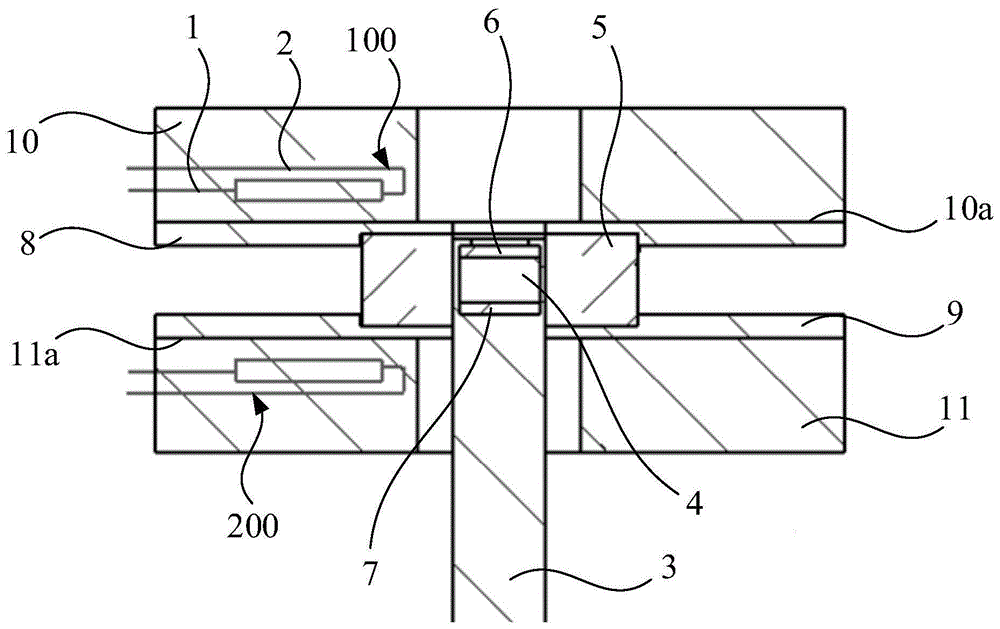
图1示出了本申请行程开关的第一实施例的示意图;FIG. 1 shows a schematic diagram of the first embodiment of the travel switch of the present application;
图2示出了本申请行程开关的第一实施例的另一示意图。FIG. 2 shows another schematic diagram of the first embodiment of the travel switch of the present application.
附图标记:Reference number:
100-第一触发构件;200-第二触发构件;1-第一簧片;2-第二簧片;3-反馈杆;4-磁体;5-阻隔环;6-第一导磁垫;7-第二导磁垫;8-第一导磁板;9-第二导磁板;10-第一安装座;10a-第一触发表面;11-第二安装座;11a-第二触发表面;h-磁组件厚度;H-阻磁厚度。100-first trigger member; 200-second trigger member; 1-first reed; 2-second reed; 3-feedback lever; 4-magnet; 5-blocking ring; 6-first magnetic conductive pad; 7- The second magnetic pad; 8- The first magnetic plate; 9- The second magnetic plate; 10- The first mount; 10a- The first trigger surface; 11- The second mount; 11a- The second trigger surface; h-thickness of magnetic components; H-thickness of magnetic resistance.
具体实施方式Detailed ways
下面将结合附图对本申请的技术方案进行清楚、完整地描述,显然,所描述的实施例是本申请一部分实施例,而不是全部的实施例。基于本申请中的实施例,本领域普通技术人员在没有做出创造性劳动前提下所获得的所有其他实施例,都属于本申请保护的范围。The technical solutions of the present application will be clearly and completely described below with reference to the accompanying drawings. Obviously, the described embodiments are part of the embodiments of the present application, but not all of the embodiments. Based on the embodiments in the present application, all other embodiments obtained by those of ordinary skill in the art without creative efforts shall fall within the protection scope of the present application.
在本申请的描述中,需要说明的是,术语“中心”、“上”、“下”、“左”、“右”、“竖直”、“水平”、“内”、“外”等指示的方位或位置关系为基于附图所示的方位或位置关系,仅是为了便于描述本申请和简化描述,而不是指示或暗示所指的装置或元件必须具有特定的方位、以特定的方位构造和操作,因此不能理解为对本申请的限制。此外,术语“第一”、“第二”、“第三”仅用于描述目的,而不能理解为指示或暗示相对重要性。In the description of this application, it should be noted that the terms "center", "upper", "lower", "left", "right", "vertical", "horizontal", "inner", "outer", etc. The indicated orientation or positional relationship is based on the orientation or positional relationship shown in the accompanying drawings, which is only for the convenience of describing the present application and simplifying the description, rather than indicating or implying that the indicated device or element must have a specific orientation or a specific orientation. construction and operation, and therefore should not be construed as limitations on this application. Furthermore, the terms "first", "second", and "third" are used for descriptive purposes only and should not be construed to indicate or imply relative importance.
在本申请的描述中,需要说明的是,除非另有明确的规定和限定,术语“安装”、“相连”、“连接”应做广义理解,例如,可以是固定连接,也可以是可拆卸连接,或一体地连接;可以是机械连接,也可以是电连接;可以是直接相连,也可以通过中间媒介间接相连,可以是两个元件内部的连通。对于本领域的普通技术人员而言,可以具体情况理解上述术语在本申请中的具体含义。In the description of this application, it should be noted that, unless otherwise expressly specified and limited, the terms "installed", "connected" and "connected" should be understood in a broad sense, for example, it may be a fixed connection or a detachable connection Connection, or integral connection; can be mechanical connection, can also be electrical connection; can be directly connected, can also be indirectly connected through an intermediate medium, can be internal communication between two elements. For those of ordinary skill in the art, the specific meanings of the above terms in this application can be understood in specific situations.
另外,各个实施例之间的技术方案可以相互结合,但是必须是以本领域普通技术人员能够实现为基础,当技术方案的结合出现相互矛盾或无法实现时应当认为这种技术方案的结合不存在,也不在本申请要求的保护范围之内。In addition, the technical solutions between the various embodiments can be combined with each other, but must be based on the realization by those of ordinary skill in the art. When the combination of technical solutions is contradictory or cannot be realized, it should be considered that the combination of such technical solutions does not exist. , is not within the scope of protection claimed in this application.
图1示出了本申请行程开关的第一实施例的示意图;图2示出了本申请行程开关的第一实施例的另一示意图。Fig. 1 shows a schematic diagram of the first embodiment of the travel switch of the present application; Fig. 2 shows another schematic diagram of the first embodiment of the travel switch of the present application.
参见图1和图2,本申请提供的行程开关的第一实施例包括第一触发构件、第二触发构件、运动构件、磁体、阻隔构件、第一导磁构件、第二导磁构件、第三导磁构件、第四导磁构件、第一安装座和第二安装座。以下将具体描述上述部件的连接关系和工作原理。1 and 2, the first embodiment of the travel switch provided by the present application includes a first trigger member, a second trigger member, a moving member, a magnet, a blocking member, a first magnetically conductive member, a second magnetically conductive member, a first Three magnetic conductive members, a fourth magnetic conductive member, a first mounting seat and a second mounting seat. The connection relationship and working principle of the above components will be described in detail below.
在实施例中,第一触发构件100和第二触发构件200均包括第一触发部和第二触发部,第一触发部和第二触发部可以分别为第一簧片1和第二簧片2。以第一簧片1为例,第一簧片1可以由可被磁化的金属材料形成,同时具有弹性,使得第一簧片1能够在一定强度的磁场的作用下弯曲。同理,第二簧片2的性质可以与第一簧片1相同,在此不再赘述。在实施例中,如图1和图2所示,以第一触发构件100的第一簧片1和第二簧片2为例,第一簧片1的第一端和第二簧片2的第一端可以经由中介部连接,使得二者形成彼此分开的状态,中介部由绝缘材料形成,其目的将在随后说明。包括第一簧片1、第二簧片2和中介部的第一触发构件100可以插入于第一安装座10内,使得第一簧片1的暴露于第一安装座10的外侧部的部分和第二簧片2的暴露于第一安装座10的外侧部的部分彼此面对。In the embodiment, the
如此,由于第一簧片1和第二簧片2所具备的上述性质,当第一簧片1和第二簧片2二者被磁场作用时,二者被磁化而朝向彼此弯曲进而吸合接触,这样在第一簧片1和第二簧片2二者分别电连接到电路的情况下,两部分电路实现导通,反之,当作用于第一簧片1和第二簧片2二者的磁场强度不足时,二者复位从而彼此分离,以断开两部分电路。也就是说,上述中介部由绝缘材料形成的目的在于,避免第一簧片1和第二簧片2在彼此分开的状态下便使得它们二者对应电连接的电路导通。In this way, due to the above-mentioned properties of the
为了便于下述部件的位置的描述,参见图1中所示出的方位,可以定义第一安装座10的下表面为第一触发表面10a,定义第二安装座11的上表面为第二触发表面11a。第一安装座10和第二安装座11可以彼此面对地安装,因此第一触发表面10a和第二触发表面11a是平行的。此外,图1中示出的第一簧片1和第二簧片2可以均与第一触发表面10a平行。以下将以图1中所示的方位进一步进行部件位置的描述。In order to facilitate the description of the positions of the following components, referring to the orientation shown in FIG. 1 , the lower surface of the first mounting
在实施例中,第三导磁构件可以安装于第一触发表面10a,第四导磁构件可以安装于第二触发表面11a。在实施例中,第三导磁构件可以为第一导磁板8,第四导磁构件可以为第二导磁板9,第一导磁板8和第二导磁板9二者均由导磁材料形成,且彼此面对的两个表面可以平行。如图1所示,第一导磁板8和第二导磁板9的部分均延伸到了第一触发构件和第二触发构件二者之间的空间中,其目的在于,将下述磁体的磁场的作用经由第一导磁板8进一步传递至第一触发构件100的第一簧片1和第二簧片2,以及经由第二导磁板9进一步传递至第二触发构件200的第一簧片1和第二簧片2,以弥补因磁体与第一簧片1和第二簧片2的距离而降低的磁场作用,确保触发构件的精准触发。In an embodiment, the third magnetically permeable member may be mounted on the
在实施例中,第一触发表面10a和第二触发表面11a之间可以安装有阻隔构件,阻隔构件可以为阻隔环5。阻隔环5形成有阻隔部,安装于运动构件的磁体可以被阻隔部限定,以下将具体说明。In an embodiment, a blocking member may be installed between the
上述阻隔部可以为阻隔通孔,阻隔通孔可以沿着竖直方向贯穿阻隔部,阻隔通孔的横截面可以为圆形,即阻隔通孔形成为圆柱形的形状。在实施例中,第一导磁板8和第二导磁板9可以形成有尺寸大于或者等于阻隔通孔的内径的孔部,第一安装座10和第二安装座11也可以形成有尺寸大于或者等于阻隔通孔的内径的孔部,使得在阻隔环5安装于第一导磁板8和第二导磁板9之间的状态下,阻隔通孔的两端均与外界环境连通。The blocking part may be a blocking through hole, the blocking through hole may penetrate the blocking part in a vertical direction, and the cross-section of the blocking through hole may be circular, that is, the blocking through hole is formed in a cylindrical shape. In the embodiment, the first magnetic
在实施例中,运动构件可以为反馈杆3,反馈杆3可以形成为圆柱形状的杆构件,其外径可以略小于阻隔通孔的内径。反馈杆3的一端(以下称磁体端)可以形成有能够被密封的腔体,磁体4可以被安装于腔体内,磁体4可以优先为永磁铁。In an embodiment, the moving member may be a
在实施例中,阻隔环5可以由导磁材料形成。当反馈杆3的磁体端位于阻隔通孔内(即反馈杆3的第一位置)时,磁体4可以被完全容纳于阻隔通孔内时,磁体4的磁场经由阻隔环5形成磁场回路,使得磁场相当于被阻隔环5阻隔,而不对任意一组第一簧片1和第二簧片2产生作用。当反馈杆3的磁体端向着阻隔通孔的外部运动(即向下或者向上运动)时,磁体逐渐移出阻隔通孔,当磁体的部分位于阻隔通孔的外部时(即反馈杆3的第二位置和第三位置,反馈杆3具有相对于阻隔环5向上运动而到达的第二位置和向下运动而到达的第三位置),以第二位置为例,磁体的磁场通经由第一导磁板8传递而作用于第一触发构件100的第一簧片1和第二簧片2,使得第一簧片1和第二簧片2经由磁力而吸合在一起,同理,反馈杆3在第三位置时的情况也是相似的。阻隔通孔位于第一触发表面10a和第二触发表面11a之间,这种夹持方式的安装使得对反馈杆3的上下行程的对照性更强,有利于行程的精度出现故障时的排查。在实施例中,反馈杆3可以安装于运动机构,运动机构可以具有与反馈杆3的轴向(即阻隔通孔的轴向)相同的运动方向,通过运动机构带动反馈杆3运动,使得行程开关完成上述的通断过程。In an embodiment, the blocking
在实施例中,位于反馈杆3的腔体内的磁体4的上侧部和下侧部还可以分别覆盖有第一导磁垫6和第二导磁垫7,第一导磁垫6和第二导磁垫7可以均由导磁材料形成。在磁体被容纳于阻隔环5的阻隔通孔内时,第一导磁垫6和第二导磁垫7也可以均被容纳于阻隔通孔内,且均参与了磁场回路的导通,进一步地防止了磁体4的磁场作用到阻隔环5的外侧。在实施例中,正如前面所描述的,反馈杆3的由第一位置到第二位置(第三位置)所运动的距离可以理解为行程开关的行程。在不设置的第一导磁垫6和第二导磁垫7的情况下,有可能使阻隔环5对磁场的阻隔不足而导致在第一位置时,第一簧片1和第二簧片2仍然能够在磁场的作用下吸合,因此,第一导磁垫6和第二导磁垫7的设置增加了行程开关的控制精度,保证了行程开关工作的可靠性。In the embodiment, the upper side and the lower side of the magnet 4 located in the cavity of the
需要说明的是,在本实施例中的反馈杆3位于第一位置时,可以是第一簧片1和第二簧片2完全不受磁体4的磁场的作用,也可以是第一簧片1和第二簧片2受到的经阻隔后的磁场的作用不足以使第一簧片1和第二簧片2彼此吸合。It should be noted that when the
在实施例中,图1和图2示出了反馈杆3的一种运动方式,在以上的描述中已经具体地进行了描述。在这种运动方式中,反馈杆3的运动方向可以垂直于第一触发表面10a(当然也垂直第二触发表面11a、第一导磁板8和第二导磁板9),这样的设置方式,有利于根据实际需要进行的对反馈杆3的行程的设计,使设计的标准化。In the embodiment, FIGS. 1 and 2 show a movement of the
在实施例中,可以定义第一导磁垫6、磁体4和第二导磁垫7三者在反馈杆3的运动方向上的尺寸之和(即图1和图2中,第一导磁垫6的上端面与第二导磁垫7的下端面之间的距离)为磁组件厚度h,第一导磁板8、阻隔环5和第二导磁板9在反馈杆3运动方向上的尺寸(即图1和图2中,第一触发表面10a与第二触发表面11a之间的距离)为阻磁厚度H。在实施例中,阻磁厚度H可以大于或者等于磁组件厚度h,以有效地实现对磁体4的磁场的阻隔,同时可以对阻磁厚度H进行调节反馈杆3的行程。In the embodiment, the sum of the dimensions of the first magnetic
也就是说,在反馈杆3位于第一位置时,允许第一导磁板8和第二导磁板9的与阻隔环5贴合的部分参与对磁体4的阻磁,即第一导磁板8和第二导磁板9具有两种作用:向从属于同一触发构件的两个簧片传递磁场作用以及在反馈杆3位于第一位置时起到阻磁作用,第一导磁板8和第二导磁板9进一步有利于提高行程开关的精度,使行程开关的导通(某一个触发构件的两簧片吸合)和关断(某一个触发构件两簧片分开)更为灵敏。这种情况下,可以理解的是,在反馈杆3的第一位置,也可以是磁体4的部分被容纳于阻隔部内,例如磁体4的下端面延伸超出阻隔通孔的下端,但仍高于第二触发表面11a。同样可以理解的是,在满足以上阻磁厚度H和磁组件厚度h的关系的情况下,在反馈杆3的第一位置时,只要使得第一簧片1和第二簧片2彼此分离,并不具体限定磁体及安装于磁体的导磁垫是否被完全容纳于阻隔通孔内,反之,反馈杆3的第二位置时,只要使得第一簧片1和第二簧片2彼此吸合,并不具体限定磁体及安装于磁体4的导磁垫是否完全脱离阻隔通孔。That is to say, when the
有利的是,若第一导磁垫6以越短的距离穿过第一触发表面10a,而使第一触发构件100的两个簧片吸合,行程开关便越能够适应小行程场景,所能完成的控制便越精确,对于第二导磁垫7也是如此。Advantageously, if the first magnetic
仍以第一实施例中的反馈杆3的第一位置和第二位置为例继续说明,在实施例中,阻磁厚度H的调节可以主要是对阻隔通孔的深度进行调节,通过更换不同的阻隔部,可以较为简便地调节反馈杆3的行程。Still taking the first position and the second position of the
此外,本申请提供的行程开关还包括第二实施例(图中未示出),以下将进行描述。第二实施例与第一实施例不同之处在于,第二实施例为单位置的行程开关。仅包括一个第一触发构件,通过其包括的第一簧片和在第二簧片在磁场的作用下形变而吸合使电路导通。因此,在实施例中,对应的还设置有第一安装座和安装于安装座的第一导磁板。In addition, the travel switch provided by the present application also includes a second embodiment (not shown in the figure), which will be described below. The difference between the second embodiment and the first embodiment is that the second embodiment is a single-position travel switch. Only one first trigger member is included, and the first reed and the second reed are deformed under the action of the magnetic field to pull in and make the circuit conduct. Therefore, in the embodiment, a first mounting seat and a first magnetic conductive plate mounted on the mounting seat are also provided correspondingly.
在本实施例中,第一簧片安装于第一安装座的方式可以与第一实施例中的方式相同,对于第一触发平面的定义也是相同的,在此不再赘述。第一导磁板可以安装于第一触发平面即第一安装座的下端面,其安装方式也可以与第一实施例中的方式相同,阻隔环可以保持设置于第一导磁板的下端面。在本实施例中,行程开关可以仅包括第一导磁垫,第一导磁垫可以设置于磁体的上端面。也就是说,在本实施例中,阻隔环、第一导磁垫以及第一导磁板仅需共同阻隔磁体的朝向第一触发构件侧的磁场(例如在反馈杆的运动方向垂直于第一触发表面时)。此外,在第二实施例中,关于磁体及安装于磁体的导磁垫与阻隔部的容纳关系仍适用于上述说明。In this embodiment, the manner in which the first reed is mounted on the first mounting seat may be the same as that in the first embodiment, and the definition of the first trigger plane is also the same, which will not be repeated here. The first magnetic conductive plate can be installed on the first trigger plane, that is, the lower end surface of the first mounting seat, and the installation method can also be the same as that in the first embodiment, and the blocking ring can be kept on the lower end surface of the first magnetic conductive plate. . In this embodiment, the travel switch may only include the first magnetic conductive pad, and the first magnetic conductive pad may be disposed on the upper end surface of the magnet. That is to say, in this embodiment, the blocking ring, the first magnetic conductive pad and the first magnetic conductive plate only need to jointly block the magnetic field of the magnet toward the first trigger member side (for example, when the movement direction of the feedback rod is perpendicular to the first magnetic field) when triggering the surface). In addition, in the second embodiment, the above description still applies to the accommodating relationship between the magnet, the magnetic conductive pad mounted on the magnet, and the blocking portion.
根据以上描述的特征,以下将具体描述行程开关的部分制造过程及使用场景。以行程开关的第一实施例为例进行说明,在实施例中,第一导磁垫6和第二导磁垫7可以通过螺钉等紧固件安装于磁体4,也可以通过滚压的方式进行安装,阻隔环5和第一导磁板8、第二导磁板9也可以通过上述方式形成为一整体,这种情况下适用于需要经常改变行程的场合,可拆卸式的连接能够给予技术人员更多的调整空间。或者,阻隔环5和第一导磁板8、第二导磁板9可以形成为一体成型结构,如此适用于对行程的需求相对固定的场合,减少装配时间。同理,第二实施例中的阻隔环、第一导磁板的制造过程也可以是类似上述的一体成型或者分体装配,其有益效果相同,在此不再赘述。According to the features described above, part of the manufacturing process and usage scenarios of the travel switch will be specifically described below. Taking the first embodiment of the travel switch as an example to illustrate, in the embodiment, the first magnetic
针对使用场景,现有技术中的磁感行程开关的保持区(磁体4位于该区域内,磁场的作用使得两个簧片不足以吸合)在感应区(磁体4位于该区域内时,两个簧片吸合)以外,保持区的范围通常为3mm至8mm,因此必须增加磁体4的行程才能控制电路正常通断,由此无法应用于小行程场景。此外,在面对恶劣环境例如高温、高压和辐照等环境时,需要将这些环境与行程开关的部件隔绝以形成屏蔽式结构,而屏蔽式的结构中通常由于磁体4不可视而导致行程开关在安装后需要多次调试,浪费人力、物力成本,增加安全隐患。For the usage scenario, the holding area of the magnetic induction limit switch in the prior art (the magnet 4 is located in this area, the action of the magnetic field makes the two reeds insufficient to attract) in the induction area (when the magnet 4 is located in this area, the two Except for one reed pull-in), the range of the holding area is usually 3mm to 8mm, so the stroke of the magnet 4 must be increased to control the normal on-off of the circuit, so it cannot be used in small stroke scenarios. In addition, in the face of harsh environments such as high temperature, high pressure, and irradiation, it is necessary to isolate these environments from the components of the limit switch to form a shielded structure. In the shielded structure, the limit switch is usually caused by the invisible magnet 4. After installation, it needs to be debugged many times, which wastes manpower and material costs and increases security risks.
本实施例提供的行程开关,事实上相当于实现了簧片周围磁场的突然增强和消失,从而使得保持区位于感应区以内,如此有效地降低了反馈杆3所需要的行程,因此能够适用于小行程应用场景,同时使采用磁场强度更高的磁体成为可能。此外,由于较为精确,安装后不需要进行调整,节约了时间和成本,通过采用高磁导率的导磁材料和适配的磁体4,本实施例中的行程开关的行程可以被控制在小于等于1mm的范围内。The travel switch provided in this embodiment is actually equivalent to realizing the sudden increase and disappearance of the magnetic field around the reed, so that the holding area is located within the sensing area, which effectively reduces the travel required by the
以上所述仅为本申请的优选实施例,并非因此限制本申请的保护范围,凡是在本申请的创新构思下,利用本申请说明书及附图内容所作的等效结构变换,或直接/间接运用在其他相关的技术领域均包括在本申请的保护范围内。The above are only the preferred embodiments of the present application, and are not intended to limit the protection scope of the present application. Under the innovative conception of the present application, the equivalent structure transformation made by the contents of the description and drawings of the present application, or the direct/indirect application All other related technical fields are included in the protection scope of this application.
Claims (10)
Priority Applications (1)
| Application Number | Priority Date | Filing Date | Title |
|---|---|---|---|
| CN202010298018.XA CN111403193A (en) | 2020-04-16 | 2020-04-16 | Travel switch |
Applications Claiming Priority (1)
| Application Number | Priority Date | Filing Date | Title |
|---|---|---|---|
| CN202010298018.XA CN111403193A (en) | 2020-04-16 | 2020-04-16 | Travel switch |
Publications (1)
| Publication Number | Publication Date |
|---|---|
| CN111403193A true CN111403193A (en) | 2020-07-10 |
Family
ID=71414130
Family Applications (1)
| Application Number | Title | Priority Date | Filing Date |
|---|---|---|---|
| CN202010298018.XA Pending CN111403193A (en) | 2020-04-16 | 2020-04-16 | Travel switch |
Country Status (1)
| Country | Link |
|---|---|
| CN (1) | CN111403193A (en) |
Citations (6)
| Publication number | Priority date | Publication date | Assignee | Title |
|---|---|---|---|---|
| GB1120140A (en) * | 1965-12-01 | 1968-07-17 | Ca Atomic Energy Ltd | Magnetic switching apparatus |
| US3937083A (en) * | 1975-01-16 | 1976-02-10 | Flowtron Industries Inc. | Temperature-compensating liquid meter |
| DE4140590C1 (en) * | 1991-12-10 | 1993-02-25 | Eckardt Ag, 7000 Stuttgart, De | Dual reed relay switching device, e.g. for electronic tachometer - has permanent magnet screened by guide elements and cylinder, located in central bore, and pistons to move magnet to select single relay |
| CN101082478A (en) * | 2006-06-01 | 2007-12-05 | 埃利斯塔替续器股份有限公司 | Safety position sensor for a cylinder, cylinder with such a position sensor |
| CN209785813U (en) * | 2019-07-09 | 2019-12-13 | 渤海船舶职业学院 | Multi-point switch |
| CN211555712U (en) * | 2020-04-16 | 2020-09-22 | 鞍山电磁阀有限责任公司 | Travel switch |
-
2020
- 2020-04-16 CN CN202010298018.XA patent/CN111403193A/en active Pending
Patent Citations (6)
| Publication number | Priority date | Publication date | Assignee | Title |
|---|---|---|---|---|
| GB1120140A (en) * | 1965-12-01 | 1968-07-17 | Ca Atomic Energy Ltd | Magnetic switching apparatus |
| US3937083A (en) * | 1975-01-16 | 1976-02-10 | Flowtron Industries Inc. | Temperature-compensating liquid meter |
| DE4140590C1 (en) * | 1991-12-10 | 1993-02-25 | Eckardt Ag, 7000 Stuttgart, De | Dual reed relay switching device, e.g. for electronic tachometer - has permanent magnet screened by guide elements and cylinder, located in central bore, and pistons to move magnet to select single relay |
| CN101082478A (en) * | 2006-06-01 | 2007-12-05 | 埃利斯塔替续器股份有限公司 | Safety position sensor for a cylinder, cylinder with such a position sensor |
| CN209785813U (en) * | 2019-07-09 | 2019-12-13 | 渤海船舶职业学院 | Multi-point switch |
| CN211555712U (en) * | 2020-04-16 | 2020-09-22 | 鞍山电磁阀有限责任公司 | Travel switch |
Similar Documents
| Publication | Publication Date | Title |
|---|---|---|
| US5575309A (en) | Solenoid actuator | |
| US5877664A (en) | Magnetic proximity switch system | |
| US3961298A (en) | Dual plunger solenoid | |
| EP2533262A1 (en) | Electromagnetic relay and method of manufacturing the same | |
| US5883557A (en) | Magnetically latching solenoid apparatus | |
| US8362859B2 (en) | Magnetically-triggered proximity switch | |
| US10184530B2 (en) | Electromagnetic connection device | |
| US20120206224A1 (en) | Magnetically-Triggered Proximity Switch | |
| US20190148094A1 (en) | Electromagnetic relay | |
| CN1904418B (en) | Electromagnetic valve | |
| JP2016149416A (en) | Linear solenoid | |
| KR20140128334A (en) | Magnetically-triggered proximity switch | |
| CN111403193A (en) | Travel switch | |
| US11326710B2 (en) | Valve with electrodynamic actuator | |
| CN211555712U (en) | Travel switch | |
| TWI692793B (en) | Electromagnetic relay | |
| CN105336553B (en) | Tripping mechanism and earth leakage protective device | |
| JP4591224B2 (en) | Electromagnetic relay | |
| CN105474335A (en) | Magnet device for locking a gear selector lever of a vehicle in a pre-determined position, method for producing a magnet device, and method for operating a magnet device | |
| CN219350087U (en) | Magnetic latching thermosensitive switch | |
| CN215891329U (en) | A solenoid valve device | |
| JP6413820B2 (en) | Linear solenoid | |
| CN207381331U (en) | An Iron Core Swing Relay | |
| US4349800A (en) | Magnetic proximity switch | |
| CN218468365U (en) | Iron core control structure |
Legal Events
| Date | Code | Title | Description |
|---|---|---|---|
| PB01 | Publication | ||
| PB01 | Publication | ||
| SE01 | Entry into force of request for substantive examination | ||
| SE01 | Entry into force of request for substantive examination |