CN111405723A - Synchronized lighting system, timing device, lighting device, and synchronized lighting control method - Google Patents
Synchronized lighting system, timing device, lighting device, and synchronized lighting control method Download PDFInfo
- Publication number
- CN111405723A CN111405723A CN202010108537.5A CN202010108537A CN111405723A CN 111405723 A CN111405723 A CN 111405723A CN 202010108537 A CN202010108537 A CN 202010108537A CN 111405723 A CN111405723 A CN 111405723A
- Authority
- CN
- China
- Prior art keywords
- lighting
- communication network
- wireless networking
- module
- synchronized
- Prior art date
- Legal status (The legal status is an assumption and is not a legal conclusion. Google has not performed a legal analysis and makes no representation as to the accuracy of the status listed.)
- Granted
Links
Images


Classifications
-
- H—ELECTRICITY
- H05—ELECTRIC TECHNIQUES NOT OTHERWISE PROVIDED FOR
- H05B—ELECTRIC HEATING; ELECTRIC LIGHT SOURCES NOT OTHERWISE PROVIDED FOR; CIRCUIT ARRANGEMENTS FOR ELECTRIC LIGHT SOURCES, IN GENERAL
- H05B47/00—Circuit arrangements for operating light sources in general, i.e. where the type of light source is not relevant
- H05B47/10—Controlling the light source
- H05B47/175—Controlling the light source by remote control
- H05B47/196—Controlling the light source by remote control characterised by user interface arrangements
- H05B47/1965—Controlling the light source by remote control characterised by user interface arrangements using handheld communication devices
-
- H—ELECTRICITY
- H04—ELECTRIC COMMUNICATION TECHNIQUE
- H04L—TRANSMISSION OF DIGITAL INFORMATION, e.g. TELEGRAPHIC COMMUNICATION
- H04L67/00—Network arrangements or protocols for supporting network services or applications
- H04L67/01—Protocols
- H04L67/12—Protocols specially adapted for proprietary or special-purpose networking environments, e.g. medical networks, sensor networks, networks in vehicles or remote metering networks
-
- H—ELECTRICITY
- H04—ELECTRIC COMMUNICATION TECHNIQUE
- H04W—WIRELESS COMMUNICATION NETWORKS
- H04W4/00—Services specially adapted for wireless communication networks; Facilities therefor
- H04W4/80—Services using short range communication, e.g. near-field communication [NFC], radio-frequency identification [RFID] or low energy communication
-
- H—ELECTRICITY
- H04—ELECTRIC COMMUNICATION TECHNIQUE
- H04W—WIRELESS COMMUNICATION NETWORKS
- H04W56/00—Synchronisation arrangements
- H04W56/001—Synchronization between nodes
- H04W56/0015—Synchronization between nodes one node acting as a reference for the others
-
- H—ELECTRICITY
- H05—ELECTRIC TECHNIQUES NOT OTHERWISE PROVIDED FOR
- H05B—ELECTRIC HEATING; ELECTRIC LIGHT SOURCES NOT OTHERWISE PROVIDED FOR; CIRCUIT ARRANGEMENTS FOR ELECTRIC LIGHT SOURCES, IN GENERAL
- H05B47/00—Circuit arrangements for operating light sources in general, i.e. where the type of light source is not relevant
- H05B47/10—Controlling the light source
- H05B47/16—Controlling the light source by timing means
-
- H—ELECTRICITY
- H05—ELECTRIC TECHNIQUES NOT OTHERWISE PROVIDED FOR
- H05B—ELECTRIC HEATING; ELECTRIC LIGHT SOURCES NOT OTHERWISE PROVIDED FOR; CIRCUIT ARRANGEMENTS FOR ELECTRIC LIGHT SOURCES, IN GENERAL
- H05B47/00—Circuit arrangements for operating light sources in general, i.e. where the type of light source is not relevant
- H05B47/10—Controlling the light source
- H05B47/175—Controlling the light source by remote control
- H05B47/19—Controlling the light source by remote control via wireless transmission
-
- Y—GENERAL TAGGING OF NEW TECHNOLOGICAL DEVELOPMENTS; GENERAL TAGGING OF CROSS-SECTIONAL TECHNOLOGIES SPANNING OVER SEVERAL SECTIONS OF THE IPC; TECHNICAL SUBJECTS COVERED BY FORMER USPC CROSS-REFERENCE ART COLLECTIONS [XRACs] AND DIGESTS
- Y02—TECHNOLOGIES OR APPLICATIONS FOR MITIGATION OR ADAPTATION AGAINST CLIMATE CHANGE
- Y02B—CLIMATE CHANGE MITIGATION TECHNOLOGIES RELATED TO BUILDINGS, e.g. HOUSING, HOUSE APPLIANCES OR RELATED END-USER APPLICATIONS
- Y02B20/00—Energy efficient lighting technologies, e.g. halogen lamps or gas discharge lamps
- Y02B20/40—Control techniques providing energy savings, e.g. smart controller or presence detection
-
- Y—GENERAL TAGGING OF NEW TECHNOLOGICAL DEVELOPMENTS; GENERAL TAGGING OF CROSS-SECTIONAL TECHNOLOGIES SPANNING OVER SEVERAL SECTIONS OF THE IPC; TECHNICAL SUBJECTS COVERED BY FORMER USPC CROSS-REFERENCE ART COLLECTIONS [XRACs] AND DIGESTS
- Y02—TECHNOLOGIES OR APPLICATIONS FOR MITIGATION OR ADAPTATION AGAINST CLIMATE CHANGE
- Y02D—CLIMATE CHANGE MITIGATION TECHNOLOGIES IN INFORMATION AND COMMUNICATION TECHNOLOGIES [ICT], I.E. INFORMATION AND COMMUNICATION TECHNOLOGIES AIMING AT THE REDUCTION OF THEIR OWN ENERGY USE
- Y02D30/00—Reducing energy consumption in communication networks
- Y02D30/70—Reducing energy consumption in communication networks in wireless communication networks
Landscapes
- Engineering & Computer Science (AREA)
- Computer Networks & Wireless Communication (AREA)
- Signal Processing (AREA)
- Health & Medical Sciences (AREA)
- Computing Systems (AREA)
- General Health & Medical Sciences (AREA)
- Medical Informatics (AREA)
- Circuit Arrangement For Electric Light Sources In General (AREA)
- Mobile Radio Communication Systems (AREA)
Abstract
本发明公开了一种同步照明系统,包括:多台同步照明装置,每台同步照明装置包括第一无线组网模块、照明控制模块和光源模块;还包括授时装置,所述授时装置包括授时控制模块,第二无线组网模块和授时供电模块,所有第一无线组网模块和第二无线组网模块组成通讯网络;控制装置,连接并传输照明配置数据到该通讯网络中,所述授时装置通过该通讯网络获取和周期性地向所有同步照明装置广播时间戳,所述同步照明装置通过该通讯网络获取照明配置数据;本发明还提供了一种授时装置、照明装置和同步照明控制方法;本发明可以提高设备的智能化同时有效降低系统能耗。
The invention discloses a synchronous lighting system, comprising: a plurality of synchronous lighting devices, each synchronous lighting device includes a first wireless networking module, a lighting control module and a light source module; and a timing device, the timing device includes a timing control module, the second wireless networking module and the timing power supply module, all the first wireless networking modules and the second wireless networking module form a communication network; the control device connects and transmits lighting configuration data to the communication network, the timing device Obtain and periodically broadcast time stamps to all synchronous lighting devices through the communication network, and the synchronous lighting devices obtain lighting configuration data through the communication network; the invention also provides a timing device, a lighting device and a synchronous lighting control method; The invention can improve the intelligence of the equipment and effectively reduce the energy consumption of the system.
Description
技术领域technical field
本发明涉及照明控制技术领域,特别是同步照明系统、授时装置、照明装置和同步照明控制方法。The invention relates to the technical field of lighting control, in particular to a synchronous lighting system, a timing device, a lighting device and a synchronous lighting control method.
背景技术Background technique
在节能环保的背景下,LED灯具因其具有出光效率高、聚光性能好而越来越多地应用于居家、商业照明领域。在商业照明中,主要包括商场、超市、门店、博物馆照明系统,这些照明系统在使用时,通常是希望被同一同步控制的,目前一般都是通过连接互联网的方式进行统一控制。In the context of energy saving and environmental protection, LED lamps are increasingly used in home and commercial lighting fields because of their high light-emitting efficiency and good light-gathering performance. In commercial lighting, it mainly includes lighting systems in shopping malls, supermarkets, stores, and museums. When these lighting systems are in use, they usually want to be controlled at the same time. At present, they are generally controlled by connecting to the Internet.
上述通过互联网云端控制虽然可以实现多台设备统一控制,但是当设备断电后往往需要重新设定时间,并且还存在照明信息外泄的可能,这是在商用照明中不希望发生的情况。Although the above-mentioned cloud control through the Internet can realize unified control of multiple devices, it is often necessary to reset the time after the device is powered off, and there is also the possibility of leakage of lighting information, which is not expected in commercial lighting.
发明内容SUMMARY OF THE INVENTION
有鉴于此,本发明提供了一种同步照明系统,以解决上述技术问题。In view of this, the present invention provides a synchronous lighting system to solve the above technical problems.
一种同步照明系统,包括:A synchronized lighting system, comprising:
多台同步照明装置,每台同步照明装置包括第一无线组网模块、照明控制模块和光源模块;a plurality of synchronous lighting devices, each of which includes a first wireless networking module, a lighting control module and a light source module;
其特征在于,还包括授时装置,所述授时装置包括授时控制模块,第二无线组网模块和授时供电模块,所有第一无线组网模块和第二无线组网模块组成通讯网络;It is characterized in that, it also includes a timing device, and the timing device includes a timing control module, a second wireless networking module and a timing power supply module, and all the first wireless networking modules and the second wireless networking modules form a communication network;
控制装置,连接并传输照明配置数据到该通讯网络中,所述授时装置通过该通讯网络获取和周期性地向所有同步照明装置广播时间戳,所述同步照明装置通过该通讯网络获取照明配置数据。a control device that connects and transmits lighting configuration data to the communication network, the timing device obtains and periodically broadcasts time stamps to all synchronized lighting devices through the communication network, and the synchronized lighting devices obtain lighting configuration data through the communication network .
优选地,所述授时供电模块包括供电电池。Preferably, the timing power supply module includes a power supply battery.
优选地,所述授时供电模块还包括外接电源插接头。Preferably, the timing power supply module further includes an external power plug connector.
优选地,所述第二无线组网模块被构建为周期性通电工作。Preferably, the second wireless networking module is configured to be powered on periodically.
优选地,所述第二无线组网模块被构建为在所述通讯网络中不可连接。Preferably, the second wireless networking module is constructed so as not to be connectable in the communication network.
优选地,其中一个第一无线组网模块被构建为在所述通讯网络中可连接,其他第一无线组网模块被构建为在所述通讯网络中不可连接。Preferably, one of the first wireless networking modules is configured to be connectable in the communication network, and the other first wireless networking modules are configured to be non-connectable in the communication network.
优选地,所述同步照明装置还包括传感模块。Preferably, the synchronous lighting device further includes a sensing module.
优选地,所述传感模块包括颜色识别传感器、温度传感器和微波传感器中的至少一种。Preferably, the sensing module includes at least one of a color recognition sensor, a temperature sensor and a microwave sensor.
优选地,所述照明配置数据包括亮度、色温、照明时间表、时间戳、传感器灵敏度中的至少一种。Preferably, the lighting configuration data includes at least one of brightness, color temperature, lighting schedule, time stamp, sensor sensitivity.
优选地,所述第一无线组网模块和第二无线组网模块采用蓝牙模块。Preferably, the first wireless networking module and the second wireless networking module use a Bluetooth module.
优选地,所述通讯网络为mesh网络。Preferably, the communication network is a mesh network.
本发明还提供了一种授时装置,包括壳体以及设置在该壳体内的授时控制模块,第二无线组网模块和授时供电模块,其特征在于,所述第二无线组网模块被构建到一通讯网络中,所述授时装置通过该通讯网络获取和周期性地向所述通讯网络广播时间戳。The present invention also provides a timing device, comprising a casing, a timing control module disposed in the casing, a second wireless networking module and a timing power supply module, characterized in that the second wireless networking module is constructed to In a communication network, the timing device obtains and periodically broadcasts a time stamp to the communication network through the communication network.
优选地,所述授时供电模块包括供电电池。Preferably, the timing power supply module includes a power supply battery.
优选地,所述授时供电模块还包括外接电源插接头。Preferably, the timing power supply module further includes an external power plug connector.
优选地,所述第二无线组网模块被构建为周期性通电工作。Preferably, the second wireless networking module is configured to be powered on periodically.
优选地,所述第二无线组网模块被构建为在所述通讯网络中不可连接。Preferably, the second wireless networking module is constructed so as not to be connectable in the communication network.
本发明还提供了一种同步照明装置,包括第一无线组网模块和照明控制模块,其特征在于,所述第一无线组网模块被构建到一通讯网络中;The present invention also provides a synchronous lighting device, comprising a first wireless networking module and a lighting control module, wherein the first wireless networking module is constructed into a communication network;
设有通过该通讯网络获取和周期性地向所述通讯网络广播时间戳的授时装置;There is a timing device that obtains and periodically broadcasts time stamps to the communication network through the communication network;
设有连接并传输照明配置数据到该通讯网络中的控制装置。There is a control device that connects and transmits lighting configuration data into the communication network.
优选地,所述第一无线组网模块被构建为在所述通讯网络中可连接。Preferably, the first wireless networking module is configured to be connectable in the communication network.
优选地,所述第一无线组网模块被构建为在所述通讯网络中不可连接。Preferably, the first wireless networking module is configured to be unconnectable in the communication network.
优选地,所述同步照明装置还包括传感模块。Preferably, the synchronous lighting device further includes a sensing module.
优选地,所述传感模块包括颜色识别传感器、温度传感器和微波传感器中的至少一种。Preferably, the sensing module includes at least one of a color recognition sensor, a temperature sensor and a microwave sensor.
本发明还提供了一种同步照明控制方法,采用上述的同步照明系统,包括以下步骤:The present invention also provides a synchronous lighting control method, which adopts the above-mentioned synchronous lighting system and includes the following steps:
001、第一无线组网模块和第二无线组网模块组成通讯网络;001. A first wireless networking module and a second wireless networking module form a communication network;
002、控制装置连接并将照明配置数据到该通讯网络中;002. The control device is connected and the lighting configuration data is added to the communication network;
003、所述授时装置获取通讯网络中时间戳并储存或者更新;003. The timing device obtains a time stamp in the communication network and stores or updates it;
004、所述授时装置周期性地向所有同步照明装置广播最新的时间戳;004. The timing device periodically broadcasts the latest time stamp to all synchronized lighting devices;
005、所述同步照明装置通过该通讯网络获取照明配置数据。005. The synchronous lighting device acquires lighting configuration data through the communication network.
优选地,在步骤004中,所述第二无线组网模块被构建为周期性通电工作。Preferably, in
优选地,步骤001中,所述第二无线组网模块被构建为在所述通讯网络中不可连接;其中一个第一无线组网模块被构建为在所述通讯网络中可连接,其他第一无线组网模块被构建为在所述通讯网络中不可连接。Preferably, in
优选地,步骤002中,控制装置通过搜索可连接的第一无线组网模块连接至所述通讯网络,并将包括时间戳的照明配置数据在所述通讯网络中进行广播。Preferably, in
优选地,步骤003与步骤004在同一周期进行,在一个工作周期内,先判断是否进行步骤003,判断是否进行步骤003的具体步骤如下:Preferably,
0031、所述授时装置周期性的使第二无线组网模块通电;0031. The timing device periodically powers on the second wireless networking module;
0032、授时装置向可连接的同步照明装置询问是否有新的时间戳,如果有进入步骤0033,如果没有进入步骤0034;0032. The timing device asks the connectable synchronous lighting device whether there is a new time stamp, if yes, go to
0033、可连接的同步照明装置有新的时间戳,则在所述通讯网络中广播时间戳,然后进行步骤003;0033. If the connectable synchronous lighting device has a new time stamp, broadcast the time stamp in the communication network, and then proceed to
0034、可连接的同步照明装置没有新的时间戳,然后进行步骤004。0034. There is no new time stamp for the connectable synchronized lighting device, and then
优选地,步骤005的具体包括:Preferably,
0051、通过控制装置的广播同步照明配置数据;0051. Synchronize the lighting configuration data through the broadcast of the control device;
0052、授时装置的广播同步时间戳;0052. The broadcast synchronization timestamp of the timing device;
0053、所述同步照明装置之间相互同步照明配置数据。0053. Synchronize lighting configuration data between the synchronized lighting devices.
其中,周期性是指根据设定的时间表进行开启和关闭,为了规矩工作,一般都是等时间周期变化,当然其中的时间间隔和工作时长也是可以不相等的,根据需要进行设定。Among them, periodic refers to opening and closing according to the set timetable. In order to work properly, it is generally changed in an equal time period. Of course, the time interval and working time can also be unequal, which can be set according to needs.
本发明的技术效果:Technical effect of the present invention:
本发明的同步照明系统,通过增设授时装置使系统内的设备可以自动校准时间戳,避免照明设备因断电而需要重新设定时间戳的问题,提高设备的智能化,同时通过对同步照明系统内的照明装置进行统一控制,可以有效降低系统能耗,并且还对授时装置的结构和工作方式进行了设定,降低授时装置的工作能耗,延长使用寿命,采用普通的电池即可以达到十年以上的工作时间。In the synchronous lighting system of the present invention, by adding a timing device, the equipment in the system can automatically calibrate the time stamp, avoid the problem that the lighting equipment needs to reset the time stamp due to power failure, and improve the intelligence of the equipment. The unified control of the lighting devices in the system can effectively reduce the energy consumption of the system, and the structure and working mode of the timing device are also set to reduce the working energy consumption of the timing device and prolong the service life. more than one year of working hours.
附图说明Description of drawings
以下结合附图描述本发明的实施例,其中:Embodiments of the present invention are described below in conjunction with the accompanying drawings, wherein:
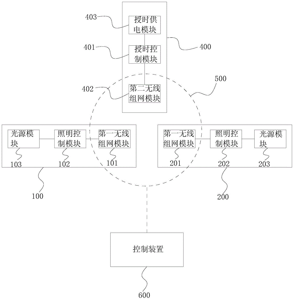
图1为本发明的一个实施例的同步照明系统的线框示意图。FIG. 1 is a schematic diagram of a wire frame of a synchronous lighting system according to an embodiment of the present invention.
图2为本发明的一个实施例的同步照明装置的线框示意图。FIG. 2 is a schematic diagram of a wire frame of a synchronous lighting device according to an embodiment of the present invention.
图3为本发明的一个实施例的同步照明系统的线框示意图。FIG. 3 is a schematic diagram of a wire frame of a synchronous lighting system according to an embodiment of the present invention.
图4为本发明的一个实施例的同步照明方法的线框流程图。FIG. 4 is a wireframe flowchart of a method for synchronizing lighting according to an embodiment of the present invention.
图5为本发明的一个实施例的同步照明方法的线框流程图。FIG. 5 is a wireframe flow chart of a method for synchronizing lighting according to an embodiment of the present invention.
具体实施方式Detailed ways
以下基于附图对本发明的具体实施例进行进一步详细说明。应当理解的是,此处对本发明实施例的说明并不用于限定本发明的保护范围。Specific embodiments of the present invention will be further described in detail below based on the accompanying drawings. It should be understood that the descriptions of the embodiments of the present invention herein are not intended to limit the protection scope of the present invention.
如图1所示,本实施例的同步照明系统,包括同步照明装置100、同步照明装置200、授时装置400和控制装置600。每台同步照明装置100(200)包括第一无线组网模块101(201)、照明控制模块102(202)和光源模块103(203)。所述授时装置400包括授时控制模块401、第二无线组网模块402和授时供电模块403。第一无线组网模块101,第一无线组网模块201和第二无线组网模块402组成通讯网络500。As shown in FIG. 1 , the synchronized lighting system of this embodiment includes a
同步照明装置的数量根据需要进行设定,除了两个以外,还可以是两个以上,结构都是相同的。照明控制模块102(202)连接光源模块103(203),输入可以采用24V或者12V供电,输出连接光源模块103(203)以及第一无线组网模块101(201)。照明控制模块102(202)主要用于接收第一无线组网模块101(201)的控制信号,控制光源模块103(203)调节亮度和光色等照明参数。The number of synchronous lighting devices can be set as required, and there may be more than two in addition to two, and the structures are all the same. The lighting control module 102 (202) is connected to the light source module 103 (203), the input can be powered by 24V or 12V, and the output is connected to the light source module 103 (203) and the first wireless networking module 101 (201). The lighting control module 102 (202) is mainly used for receiving a control signal from the first wireless networking module 101 (201), and controlling the light source module 103 (203) to adjust lighting parameters such as brightness and light color.
控制装置600连接并传输照明配置数据到该通讯网络500中,所述授时装置400通过该通讯网络500获取和周期性地向同步照明装置100和同步照明装置200广播时间戳,同步照明装置100和同步照明装置200通过该通讯网络500获取照明配置数据。The
其中,控制装置600用于将照明配置数据传输到通讯网络500中,照明配置数用于控制同步照明装置,包括且不限于亮度、色温、照明时间表、时间戳、传感器灵敏度,优选的,所述照明配置数据包括亮度、色温、照明时间表、时间戳、传感器灵敏度中的至少一种。The
除了时间戳以外,其他的照明配置数据在确定后很少会变化,而时间戳则会因为同步照明装置断电等原因而不准确,而每次同步照明装置断电后即需要通过控制装置600进行校准会很不方便,而通过互联网控制不仅需要增加连接设备,而且存在泄露信息的风险。因此,本实施例中,通过设置授时装置400周期性地向所有同步照明装置广播时间戳的方式来对通讯网络500中的所有同步照明装置进行时间戳同步,从而在一定范围内保持通讯网络500中所有同步照明装置的时间戳同步。Except for the time stamp, other lighting configuration data will rarely change after being determined, and the time stamp will be inaccurate due to reasons such as the power failure of the synchronized lighting device. Doing calibration can be inconvenient, and controlling via the internet not only requires additional connected devices, but also risks leaking information. Therefore, in this embodiment, by setting the
控制装置600可以是手机、遥控器等控制设备,优选的,本实施例的控制装置600为手机,通过安装专门的灯具控制app来实现连接并传输照明配置数据到该通讯网络500。The
授时供电模块403用于为授时装置400供电,为了保持持续通电,避免断电而导致时间戳不准,本实施例的授时供电模块403包括供电电池4031。供电电池4031可以持续为授时控制模块401供电,维持时间戳记录。同时,为了兼顾通用性,另一种实施例的授时供电模块403还包括外接电源插接头4032。电源插接头4032可以外接电源为授时控制模块401供电,也可以为供电电池4031充电。授时控制模块401能够根据国家自动判断冬令时和夏令时,并进行相应的调整。The timing
为了延长供电电池4031使用时长,一般在10年以上,避免更换,另一种实施例的第二无线组网模块402被构建为周期性通电工作。In order to prolong the use time of the power supply battery 4031, which is generally more than 10 years, to avoid replacement, the second
为了进一步降低能耗,延长供电电池4031使用时长,另一种实施例的第二无线组网模块402被构建为在所述通讯网络500中不可连接。In order to further reduce energy consumption and prolong the use time of the power supply battery 4031 , the second
为了尽量少的设备被发现,为了安全性防止别人发现从而破坏通讯网络500,另一种实施例的通讯网络500,其中一个第一无线组网模块101被构建为在所述通讯网络500中可连接,其他的第一无线组网模块201被构建为在所述通讯网络500中不可连接。In order to find as few devices as possible, and to prevent others from discovering and destroying the
另一种实施例的通讯网络500,第一无线组网模块101,第一无线组网模块201和第二无线组网模块402采用蓝牙模块。所述通讯网络500为mesh网络,蓝牙mesh自组网不需要网关,可以直接和手机连接,将网络内的设备数量降至最低,成本低、功耗低。In the
如图2所示,另一种实施例的同步照明系统,同步照明装置100(200)还包括传感模块700。传感模块700可以将外界的反馈信息传递给照明控制模块102(202),从而改变照明配置数据中的参数,达到更适合的照明效果。As shown in FIG. 2 , in the synchronous lighting system of another embodiment, the synchronous lighting device 100 ( 200 ) further includes a
另一种实施例的同步照明系统,传感模块700包括颜色识别传感器701、温度传感器702和微波传感器703中的至少一种。微波传感器703可以感应人接近,在人接近时控制照明控制模块102(202)将灯光调亮,然后感应到无人时延迟一段时间后将灯光调暗。温度传感器702可以采集冰柜内的环境温度,并且通过显示数码管进行显示。颜色识别传感器701能够自动识别冰柜货架上的货品是肉类还是其他货品,从而调节光源模块103(203)选择照肉的光色和非照肉的光色。In another embodiment of the synchronous lighting system, the
如图3所示,上述一种实施例的授时装置400的时间戳同步机制过程如下:As shown in FIG. 3 , the process of the time stamp synchronization mechanism of the
控制装置600(例如手机)在搜索到可连接的第一无线组网模块101并且连接整个通讯网络500后,会把当前的时间戳广播给通讯网络500内的所有设备,只要设备的无线组网模块通电,都会收到这个时间戳。After the control device 600 (such as a mobile phone) searches for the connectable first
由于授时装置400采用电池供电,需要工作在低功耗模式下。因此第二无线组网模块402的电源需要授时控制模块401控制,周期性的通电,发送指令,然后再断电这样一个流程。当第二无线组网模块402处于断电状态时无法收到通讯网络500内的任何指令,此时,控制装置600无法直接发送时间戳给授时装置400。在此采用可连接的第一无线组网模块101作为中转,具体机制如下:Since the
授时控制模块401控制第二无线组网模块402通电,发送指令给可连接的第一无线组网模块101,询问时间戳。可连接的第一无线组网模块101如果收到过控制装置600发送的新的时间戳,则广播通讯网络500内的所有设备,第二无线组网模块402接收时间戳后断电,等待下一次通电。可连接的第一无线组网模块101如果没有收到过控制装置600发送的新的时间戳,则发送指令告诉授时装置400,授时装置400则通过第二无线组网模块402广播授时控制模块401储存的时间戳给通讯网络500内的所有设备(所有设备的时间戳得到同步),广播后则断电,等待下一次通电。The
除此之外,通讯网络500内,除了授时装置400外,同步照明装置之间设置了定时任务同步机制,过程如下:In addition, in the
通讯网络500内,除授时装置400外的每个照明控制模块102(202)都保存一张定时任务表,并且定时进行同步,保持一致,每个照明控制模块102(202)都会根据当前保存的定时任务计算出一个校验值(CRC16循环冗余校验)。In the
可连接的第一无线组网模块101则会定时广播这个校验值给第一无线组网模块201,如果照明控制模块202发现自己的校验值和收到的不一致,则广播指令给可连接的第一无线组网模块101请求同步任务表,照明控制模块102通过可连接的第一无线组网模块101收到请求后,广播定时任务表给第一无线组网模块201,照明控制模块202进行解析同步。这样定时任务表就得到了同步,然后每个设备根据自己的定时任务表执行相应的动作。The first
具体的,如图4所示,本实施例的同步照明控制方法,采用上述一种实施例的同步照明系统,包括以下步骤:Specifically, as shown in FIG. 4 , the synchronous lighting control method of this embodiment adopts the synchronous lighting system of the above-mentioned one embodiment, and includes the following steps:
001、第一无线组网模块101,第一无线组网模块201和第二无线组网模块402组成通讯网络500;001. A first
所述第二无线组网模块402被构建为在所述通讯网络500中不可连接;其中一个第一无线组网模块101被构建为在所述通讯网络500中可连接,其他第一无线组网模块201被构建为在所述通讯网络500中不可连接;The second
002、控制装置600连接并将照明配置数据到该通讯网络500中;002. The
控制装置600通过搜索可连接的第一无线组网模块101连接至所述通讯网络500,并将包括时间戳的照明配置数据在所述通讯网络500中进行广播。The
当控制装置600采用手机时,在手机中的App启动后,会去连接对应的通讯网络500,连接后,App会去获取智能设备的时间,将时间转换成格林尼治时间后发送给通讯网络500中的设备,这样设备就不会受时区影响。其中,同步时间戳是同步给授时装置400,但是授时装置400周期性开启,经常休眠(为了降低能耗),所以把时间戳同步给其他设备,通过其他设备再同步给授时装置400,使用广播命令。When the
003、所述授时装置400获取通讯网络500中时间戳并储存或者更新;003. The
004、所述授时装置400周期性地向所有同步照明装置100和同步照明装置200广播最新的时间戳;004. The
所述第二无线组网模块402被构建为周期性通电工作;The second
005、所述同步照明装置100和同步照明装置200通过该通讯网络500获取照明配置数据。005. The
如图5所示,另一种实施例的同步照明控制方法,步骤003与步骤004在同一周期进行,在一个工作周期内,先判断是否进行步骤003,判断是否进行步骤003的具体步骤如下:As shown in Figure 5, in another embodiment of the synchronous lighting control method,
0031、所述授时装置400周期性的使第二无线组网模块402通电;0031. The
0032、授时装置400向可连接的同步照明装置100询问是否有新的时间戳,如果有进入步骤0033,如果没有进入步骤0034;0032. The
0033、可连接的同步照明装置100有新的时间戳,则在所述通讯网络500中广播时间戳,然后进行步骤003;0033. If the connectable
0034、可连接的同步照明装置100没有新的时间戳,然后进行步骤004。0034 , the connectable
步骤005的具体包括:The specifics of
0051、通过控制装置600的广播同步照明配置数据;0051. Synchronize the lighting configuration data through the broadcast of the
0052、授时装置400的广播同步时间戳;0052. The broadcast synchronization timestamp of the
0053、所述同步照明装置100和同步照明装置200之间相互同步照明配置数据。0053. The
以上仅为本发明的较佳实施例,并不用于局限本发明的保护范围,任何在本发明精神内的修改、等同替换或改进等,都涵盖在本发明的权利要求范围内。The above are only preferred embodiments of the present invention, and are not intended to limit the protection scope of the present invention. Any modifications, equivalent replacements or improvements within the spirit of the present invention are all included within the scope of the claims of the present invention.
Claims (27)
Priority Applications (3)
| Application Number | Priority Date | Filing Date | Title |
|---|---|---|---|
| CN202010108537.5A CN111405723B (en) | 2020-02-21 | 2020-02-21 | Synchronous lighting system, timing device, lighting device and synchronous lighting control method |
| PCT/EP2020/081975 WO2021164906A1 (en) | 2020-02-21 | 2020-11-12 | Synchronous lighting system and synchronous lighting control method |
| EP20808314.7A EP4108051A1 (en) | 2020-02-21 | 2020-11-12 | Synchronous lighting system and synchronous lighting control method |
Applications Claiming Priority (1)
| Application Number | Priority Date | Filing Date | Title |
|---|---|---|---|
| CN202010108537.5A CN111405723B (en) | 2020-02-21 | 2020-02-21 | Synchronous lighting system, timing device, lighting device and synchronous lighting control method |
Publications (2)
| Publication Number | Publication Date |
|---|---|
| CN111405723A true CN111405723A (en) | 2020-07-10 |
| CN111405723B CN111405723B (en) | 2024-02-06 |
Family
ID=71413172
Family Applications (1)
| Application Number | Title | Priority Date | Filing Date |
|---|---|---|---|
| CN202010108537.5A Active CN111405723B (en) | 2020-02-21 | 2020-02-21 | Synchronous lighting system, timing device, lighting device and synchronous lighting control method |
Country Status (3)
| Country | Link |
|---|---|
| EP (1) | EP4108051A1 (en) |
| CN (1) | CN111405723B (en) |
| WO (1) | WO2021164906A1 (en) |
Cited By (3)
| Publication number | Priority date | Publication date | Assignee | Title |
|---|---|---|---|---|
| CN114047689A (en) * | 2021-11-17 | 2022-02-15 | 广州易而达科技股份有限公司 | Lighting equipment control method and device, lighting equipment and storage medium |
| EP4040919A1 (en) * | 2021-02-09 | 2022-08-10 | Self Electronics Co., Ltd. | Automatic lighting system and control method |
| CN115175397A (en) * | 2022-08-08 | 2022-10-11 | 广东群宇互动科技有限公司 | Building blocks granule formula intelligence LED lamp |
Citations (11)
| Publication number | Priority date | Publication date | Assignee | Title |
|---|---|---|---|---|
| CN102118206A (en) * | 2011-02-23 | 2011-07-06 | 尚雪峰 | Broadcast principle-based lighting equipment wireless network deployment method and system |
| EP2393342A1 (en) * | 2010-06-04 | 2011-12-07 | Michel Picariello | Network of synchronous standalone ground lights |
| CN102547969A (en) * | 2012-02-24 | 2012-07-04 | 电子科技大学 | High-accuracy wireless clock synchronization system for power system |
| CN203104857U (en) * | 2012-10-31 | 2013-07-31 | 湖南辰东科技有限公司 | Aviation obstruction beacon monitoring system |
| CN203206520U (en) * | 2013-01-29 | 2013-09-18 | 杭州银江智慧城市技术有限公司 | Intelligent urban road illumination control apparatus based on Beidou accurate positioning and time service |
| CN203387714U (en) * | 2013-03-29 | 2014-01-08 | 苏州博络克信息技术服务有限公司 | City illumination single lamp monitoring system based on Beidou satellite navigation system |
| US20150296599A1 (en) * | 2014-04-11 | 2015-10-15 | Wireless Environment, Llc | Modular coordinated lighting system |
| CN105264831A (en) * | 2013-03-26 | 2016-01-20 | 赛西蒂系统股份有限公司 | Sensor nodes with multicast transmissions in lighting sensory network |
| CN105680975A (en) * | 2016-03-07 | 2016-06-15 | 浙江大学 | Time synchronization method of master-slave structure multi-node network |
| KR20160086104A (en) * | 2015-01-09 | 2016-07-19 | 주식회사 아이티원 | A method for synchronizing the time of a lighting apparatus and the apparatus for synchronizing the time thereof |
| CN106341879A (en) * | 2016-05-24 | 2017-01-18 | 北京动量科技有限责任公司 | GPS time reference-based multi-point synchronous communication method and device |
Family Cites Families (3)
| Publication number | Priority date | Publication date | Assignee | Title |
|---|---|---|---|---|
| RS60607B1 (en) * | 2012-04-27 | 2020-08-31 | Schreder Sa | Distributed lighting networks |
| DE102016217683A1 (en) * | 2016-09-15 | 2018-03-15 | Tridonic Gmbh & Co. Kg | Synchronization of transmission nodes |
| US10433270B1 (en) * | 2018-06-13 | 2019-10-01 | Verizon Patent And Licensing Inc. | Synchronization for battery powered IoT networks |
-
2020
- 2020-02-21 CN CN202010108537.5A patent/CN111405723B/en active Active
- 2020-11-12 EP EP20808314.7A patent/EP4108051A1/en active Pending
- 2020-11-12 WO PCT/EP2020/081975 patent/WO2021164906A1/en not_active Ceased
Patent Citations (11)
| Publication number | Priority date | Publication date | Assignee | Title |
|---|---|---|---|---|
| EP2393342A1 (en) * | 2010-06-04 | 2011-12-07 | Michel Picariello | Network of synchronous standalone ground lights |
| CN102118206A (en) * | 2011-02-23 | 2011-07-06 | 尚雪峰 | Broadcast principle-based lighting equipment wireless network deployment method and system |
| CN102547969A (en) * | 2012-02-24 | 2012-07-04 | 电子科技大学 | High-accuracy wireless clock synchronization system for power system |
| CN203104857U (en) * | 2012-10-31 | 2013-07-31 | 湖南辰东科技有限公司 | Aviation obstruction beacon monitoring system |
| CN203206520U (en) * | 2013-01-29 | 2013-09-18 | 杭州银江智慧城市技术有限公司 | Intelligent urban road illumination control apparatus based on Beidou accurate positioning and time service |
| CN105264831A (en) * | 2013-03-26 | 2016-01-20 | 赛西蒂系统股份有限公司 | Sensor nodes with multicast transmissions in lighting sensory network |
| CN203387714U (en) * | 2013-03-29 | 2014-01-08 | 苏州博络克信息技术服务有限公司 | City illumination single lamp monitoring system based on Beidou satellite navigation system |
| US20150296599A1 (en) * | 2014-04-11 | 2015-10-15 | Wireless Environment, Llc | Modular coordinated lighting system |
| KR20160086104A (en) * | 2015-01-09 | 2016-07-19 | 주식회사 아이티원 | A method for synchronizing the time of a lighting apparatus and the apparatus for synchronizing the time thereof |
| CN105680975A (en) * | 2016-03-07 | 2016-06-15 | 浙江大学 | Time synchronization method of master-slave structure multi-node network |
| CN106341879A (en) * | 2016-05-24 | 2017-01-18 | 北京动量科技有限责任公司 | GPS time reference-based multi-point synchronous communication method and device |
Non-Patent Citations (2)
| Title |
|---|
| 王文嘉;崔宏磊;: "舰用网络授时技术设计分析", 舰船电子工程, no. 11, pages 21 - 24 * |
| 白瑞林;李博;张道;: "基于GPS的同步数字照明控制系统的设计", 计算机工程与科学, no. 08, pages 160 - 162 * |
Cited By (4)
| Publication number | Priority date | Publication date | Assignee | Title |
|---|---|---|---|---|
| EP4040919A1 (en) * | 2021-02-09 | 2022-08-10 | Self Electronics Co., Ltd. | Automatic lighting system and control method |
| CN114047689A (en) * | 2021-11-17 | 2022-02-15 | 广州易而达科技股份有限公司 | Lighting equipment control method and device, lighting equipment and storage medium |
| CN114047689B (en) * | 2021-11-17 | 2023-03-24 | 广州易而达科技股份有限公司 | Lighting equipment control method and device, lighting equipment and storage medium |
| CN115175397A (en) * | 2022-08-08 | 2022-10-11 | 广东群宇互动科技有限公司 | Building blocks granule formula intelligence LED lamp |
Also Published As
| Publication number | Publication date |
|---|---|
| CN111405723B (en) | 2024-02-06 |
| EP4108051A1 (en) | 2022-12-28 |
| WO2021164906A1 (en) | 2021-08-26 |
Similar Documents
| Publication | Publication Date | Title |
|---|---|---|
| KR101678728B1 (en) | Method and Apparatus for Monitoring of Environment | |
| US8134942B2 (en) | Communication protocol for low-power network applications and a network of sensors using the same | |
| JP6257820B1 (en) | Sensor device and sensor network system | |
| CN111405723A (en) | Synchronized lighting system, timing device, lighting device, and synchronized lighting control method | |
| US11082916B2 (en) | Low power gateway | |
| CN106061064A (en) | Intelligent light control system for intelligent city | |
| JP2014107762A (en) | Sensor data collection system | |
| US9857233B2 (en) | Low-power user interface device for environmental monitoring system | |
| CN105988446A (en) | Area-based group switch control system | |
| JP5830411B2 (en) | Radio management system and transmission management method | |
| JP5425614B2 (en) | Time synchronization method, control system, and measuring apparatus | |
| US9516725B2 (en) | Distributed lighting networks | |
| US11595889B2 (en) | Determining a duty schedule for a group of lighting devices providing a similar lighting service | |
| RU120308U1 (en) | INTELLIGENT LED LIGHTING SYSTEM AND LIGHT INTELLECTUAL LED LIGHTING SYSTEM | |
| JP6303062B1 (en) | Sensor device | |
| WO2024083709A1 (en) | Networked lighting system | |
| US20240314912A1 (en) | Circadian lighting system | |
| JP7502155B2 (en) | Switching device | |
| CN105022256A (en) | Design method of pointer type multifunction intelligent clock | |
| JP6303061B1 (en) | Sensor device | |
| JP7615391B1 (en) | Outdoor lighting system and outdoor lighting device | |
| WO2026058955A1 (en) | Outdoor lighting system and outdoor lighting device | |
| JP3750654B2 (en) | Communication system and communication adapter device used therefor | |
| JP2026053924A (en) | Street lighting systems and street lighting devices | |
| CN119364490A (en) | Data transmission method and device, storage medium and electronic device |
Legal Events
| Date | Code | Title | Description |
|---|---|---|---|
| PB01 | Publication | ||
| PB01 | Publication | ||
| SE01 | Entry into force of request for substantive examination | ||
| SE01 | Entry into force of request for substantive examination | ||
| GR01 | Patent grant | ||
| GR01 | Patent grant |