CN111406155A - Side channel blower, in particular secondary blower for an internal combustion engine - Google Patents
Side channel blower, in particular secondary blower for an internal combustion engine Download PDFInfo
- Publication number
- CN111406155A CN111406155A CN201880076805.0A CN201880076805A CN111406155A CN 111406155 A CN111406155 A CN 111406155A CN 201880076805 A CN201880076805 A CN 201880076805A CN 111406155 A CN111406155 A CN 111406155A
- Authority
- CN
- China
- Prior art keywords
- blower
- channel
- outlet
- conveying
- side edge
- Prior art date
- Legal status (The legal status is an assumption and is not a legal conclusion. Google has not performed a legal analysis and makes no representation as to the accuracy of the status listed.)
- Granted
Links
Images


Classifications
-
- F—MECHANICAL ENGINEERING; LIGHTING; HEATING; WEAPONS; BLASTING
- F04—POSITIVE - DISPLACEMENT MACHINES FOR LIQUIDS; PUMPS FOR LIQUIDS OR ELASTIC FLUIDS
- F04D—NON-POSITIVE-DISPLACEMENT PUMPS
- F04D29/00—Details, component parts, or accessories
- F04D29/08—Sealings
- F04D29/083—Sealings especially adapted for elastic fluid pumps
-
- F—MECHANICAL ENGINEERING; LIGHTING; HEATING; WEAPONS; BLASTING
- F04—POSITIVE - DISPLACEMENT MACHINES FOR LIQUIDS; PUMPS FOR LIQUIDS OR ELASTIC FLUIDS
- F04D—NON-POSITIVE-DISPLACEMENT PUMPS
- F04D23/00—Other rotary non-positive-displacement pumps
- F04D23/008—Regenerative pumps
-
- F—MECHANICAL ENGINEERING; LIGHTING; HEATING; WEAPONS; BLASTING
- F04—POSITIVE - DISPLACEMENT MACHINES FOR LIQUIDS; PUMPS FOR LIQUIDS OR ELASTIC FLUIDS
- F04D—NON-POSITIVE-DISPLACEMENT PUMPS
- F04D29/00—Details, component parts, or accessories
- F04D29/40—Casings; Connections of working fluid
- F04D29/42—Casings; Connections of working fluid for radial or helico-centrifugal pumps
- F04D29/4206—Casings; Connections of working fluid for radial or helico-centrifugal pumps especially adapted for elastic fluid pumps
- F04D29/4226—Fan casings
Landscapes
- Engineering & Computer Science (AREA)
- Mechanical Engineering (AREA)
- General Engineering & Computer Science (AREA)
- Structures Of Non-Positive Displacement Pumps (AREA)
Abstract
带有用于最小化噪声排放的装置的侧通道鼓风机是已知的,然而其通常仍有不足,并且会限制需要输送的体积流量或具有较低的效率。因此,本发明提出了一种侧通道鼓风机,其中第一侧边缘(64)和第二侧边缘(66)张成第一平面E1,该第一平面E1与由排出口(60)张成的第二平面E2成一个角度α≥30°,通过这种方式,使出口开口(62)伸入到径向界壁(33)中。通过这样的实施例,可以显着提高效率和要输送的最大体积流量。
Side-channel blowers with devices for minimizing noise emissions are known; however, they are generally inadequate and can limit the volumetric flow rate to be delivered or have low efficiency. Therefore, the present invention proposes a side-channel blower in which a first side edge (64) and a second side edge (66) are stretched to form a first plane E1 , which forms an angle α ≥ 30° with a second plane E2 stretched by the outlet (60), thereby allowing the outlet opening (62) to extend into the radial boundary wall (33). With this embodiment, efficiency and the maximum volumetric flow rate to be delivered can be significantly improved.
Description
技术领域technical field
本发明涉及侧通道鼓风机,特别是用于内燃机的二次鼓风机,所述侧通道鼓风机具有多部分壳体,多部分壳体具有至少一个第一壳体部分和第二壳体部分,该第一壳体部分被设计为罐体部分,该第二壳体部分被设计为盖部分,其中,罐体部分和盖部分在分界面内通过接在中间的密封构件彼此连接并包围成鼓风机室,其中,形成有入口和出口,该入口经由入口区域通向至少一个具有径向界壁的基本呈环形延伸的输送通道,所述侧通道鼓风机具有叶轮,该叶轮可以通过驱动单元来驱动,以可旋转的方式安装在壳体中,并具有与相对的输送通道配合的输送叶片,并且所述侧通道鼓风机具有在入口和出口之间的中断区域,在该中断区域中,至少一个输送通道在圆周方向上被中断,其中,出口具有出口通道部分,至少一个输送通道通向该出口通道部分,其中,出口通道部分具有向外的排出口和指向输送通道的、具有第一侧边缘和第二侧边缘的出口开口,其中,第一侧边缘是中断区域的一部分,并且第二侧边缘是径向界壁的一部分。The invention relates to a side channel blower, in particular a secondary blower for an internal combustion engine, having a multi-part housing with at least a first housing part and a second housing part, the first housing part The housing part is designed as a tank part and the second housing part is designed as a cover part, wherein the tank part and the cover part are connected to each other in the interface by an intermediate sealing member and enclose a blower chamber, wherein , an inlet and an outlet are formed which lead via the inlet region to at least one substantially annularly extending conveying channel with radial boundary walls, the side channel blower having an impeller which can be driven by a drive unit to be rotatable is mounted in the housing in such a way that it has conveying vanes cooperating with opposing conveying channels, and the side channel blower has an interrupted area between the inlet and the outlet in which at least one conveying channel is in the circumferential direction is interrupted at the top, wherein the outlet has an outlet channel portion to which at least one conveying channel leads, wherein the outlet channel portion has an outward discharge opening and a first side edge and a second side edge directed towards the conveying channel The outlet opening of , wherein the first side edge is part of the interrupted region and the second side edge is part of the radial boundary wall.
背景技术Background technique
此类侧通道鼓风机或侧通道泵是已知的,并且已经在多个申请中都有描述。在机动车中,这些侧通道鼓风机例如用于输送燃料或将二次空气吹入排气系统。驱动通常通过电动机实现,该电动机可驱动叶轮。叶轮在其圆周处基本上被构造成使得该叶轮与轴向相对的输送通道形成周向的涡流通道。输送叶片从叶轮形成涡流通道的部分沿输送通道的构造在外壳中的相对部分的方向垂直地伸出,使得在输送叶片之间形成凹穴。当叶轮旋转时,在凹穴中被输送的流体通过输送叶片在圆周方向和径向方向上加速,使得在输送通道中产生周向的涡流。Such side channel blowers or side channel pumps are known and have been described in various applications. In motor vehicles, these side channel blowers are used, for example, to deliver fuel or to blow secondary air into the exhaust system. Drive is usually accomplished by an electric motor, which drives the impeller. The impeller is substantially configured at its circumference such that it forms a circumferential swirl channel with the axially opposite delivery channel. The conveying vanes project perpendicularly from the portion of the impeller forming the swirl channel in the direction of the opposite portion of the conveying channel constructed in the casing, so that pockets are formed between the conveying vanes. When the impeller rotates, the fluid conveyed in the pockets is accelerated in the circumferential and radial directions by the conveying vanes, so that a circumferential vortex is generated in the conveying channel.
已知一类侧通道鼓风机,其中在壳体部分中的叶轮的轴向侧上仅构成一个输送通道,而另一类侧通道鼓风机的叶轮的两个轴向侧上都构成有输送通道,在此,两个输送通道彼此流体连接。对于这类侧通道鼓风机,输送通道中的一个形成在用作盖体的壳体部分中,而另一个输送通道形成在通常附接有驱动单元的壳体部分中,叶轮至少以抗扭的方式布置在驱动单元的轴上。One type of side channel blower is known, in which only one conveying channel is formed on the axial side of the impeller in the housing part, while another type of side channel blower has a conveying channel formed on both axial sides of the impeller, at Thus, the two delivery channels are fluidly connected to each other. For this type of side channel blower, one of the delivery channels is formed in the housing part serving as a cover and the other delivery channel is formed in the housing part to which the drive unit is usually attached, the impeller at least in a torsion-resistant manner Arranged on the shaft of the drive unit.
为了获得可能的最佳输送或压力增加,必须使用输送通道的圆周的尽可能大部分。因此,入口和出口必须在叶轮的运行方向上在圆周上尽可能相隔较远,在此,通过中断区域来防止入口和出口之间的短路流动。这类侧通道鼓风机的问题已被证实是存在高噪声,该噪声特别是由于在输送的空气中突然的压力冲击而产生的脉动引起的。In order to obtain the best possible delivery or pressure increase, the greatest possible portion of the circumference of the delivery channel must be used. Therefore, the inlet and outlet must be as far apart as possible circumferentially in the running direction of the impeller, where a short-circuit flow between inlet and outlet is prevented by interrupting regions. A problem with this type of side channel blower has been proven to be high noise, especially due to pulsations caused by sudden pressure shocks in the conveyed air.
这类压力冲击尤其紧接着每个输送机叶片扫过中断区域开始处之后出现,因为在输送机叶片之间的凹穴中仍然存在压缩空气,该压缩空气还没有通过出口完全排出,当到达中断区域时,其突然向壁面加速。这导致噪声排放显着增加。This type of pressure shock occurs especially immediately after each conveyor blade sweeps over the beginning of the interruption area, because compressed air is still present in the pockets between the conveyor blades, which has not yet been fully expelled through the outlet, when the interruption is reached. area, it suddenly accelerates towards the wall. This results in a significant increase in noise emissions.
为避免这种情况,在DE 10 2009 006 652中提出了一种用于输送流体的泵,以特殊的方式设计出口的出口开口。然而,事实证明,尽管压力冲击可减小并且相应地减少了噪声排放,但是效率仍然太低。并且,仍希望增加可能的最大通量。To avoid this, a pump for conveying fluid is proposed in
发明内容SUMMARY OF THE INVENTION
因此,本发明所要解决的技术问题是发明一种侧通道鼓风机,利用该侧通道鼓风机可以以简单且廉价的方式避免上述缺点。Therefore, the technical problem to be solved by the present invention is to invent a side channel blower with which the above mentioned disadvantages can be avoided in a simple and inexpensive manner.
此技术问题通过主权利要求的特征部分解决。在叶轮的径向内部区域中,流体在转子叶片之间流动,并在径向外部区域中离开输送叶片之间的凹穴。This technical problem is partly solved by the features of the main claim. In the radially inner region of the impeller, the fluid flows between the rotor blades and leaves the pockets between the conveying blades in the radially outer region.
因此,第一侧边缘和第二侧边缘张成第一平面E1,该第一平面E1与由排出口张成的第二平面E2成一个角度α≥30°,通过这种方式,出口开口伸入到径向界壁中,在从输送通道到出口的出口通道部分的过渡区域中能够发生真正的切向流动。因此,效率可从根本上被提高,并且也能够达到更高的工作压力。Therefore, the first side edge and the second side edge are stretched to form a first plane E 1 , which forms an angle α≥30° with the second plane E 2 stretched by the discharge opening, in this way, The outlet opening protrudes into the radial boundary wall, and a true tangential flow can take place in the transition region from the delivery channel to the outlet channel portion of the outlet. Thus, efficiency can be fundamentally improved and higher working pressures can also be achieved.
有利地,分界面在盖部分中的输送通道的底面的高度处或在盖部分中的输送通道的底面的下方延伸,因此出口通道部分平均地可以构造得更大,因此可以再度提高通量。在此,分界面可以有利地呈阶梯状延伸,并且可以在凹槽中构造作为液体密封的密封构件。通过这种方式确保了没有密封材料进入鼓风机室。Advantageously, the dividing surface extends at the level of the bottom surface of the conveying channel in the cover part or below the bottom surface of the conveying channel in the cover part, so that the outlet channel part can be constructed larger on average and thus the throughput can be increased again. In this case, the interface can advantageously extend in a stepped manner and can be formed in the groove as a liquid-tight sealing member. In this way it is ensured that no sealing material enters the blower chamber.
将盖部分连接至驱动单元可以实现特别容易制造的布置方式。在此,在盖部分中应设有用于安装驱动轴的孔。然后,罐体部分将侧通道鼓风机相对外部封闭。Connecting the cover part to the drive unit enables a particularly easy-to-manufacture arrangement. Here, holes for mounting the drive shaft should be provided in the cover part. The tank portion then encloses the side channel blower with respect to the outside.
因此,提供一种侧通道鼓风机,其中,与已知的侧通道鼓风机相比,其效率和最大可达到的通量可以显着提高。Accordingly, a side channel blower is provided wherein the efficiency and maximum achievable flux can be significantly increased compared to known side channel blowers.
附图说明Description of drawings
附图中示出了根据本发明的侧通道鼓风机的实施例,并且在下文进行描述。An embodiment of a side channel blower according to the invention is shown in the drawings and described below.
图1以剖视图示出了侧通道鼓风机的侧视图。Figure 1 shows a side view of a side channel blower in cross section.
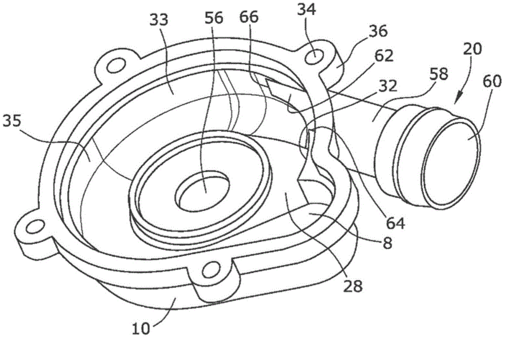
图2示出了图1的侧通道泵的罐体部分的立体图。FIG. 2 shows a perspective view of the tank portion of the side channel pump of FIG. 1 .
图3示出了图1的侧通道泵的罐体部分的俯视图。FIG. 3 shows a top view of the tank portion of the side channel pump of FIG. 1 .
具体实施方式Detailed ways
在附图1中图示的侧通道鼓风机由两部分式壳体2和例如用于输送空气的叶轮4组成,叶轮4以可旋转的方式安装在壳体2中并由驱动单元3驱动。空气通过轴向入口6到达第一壳体部分10的入口区域8(见图2),该第一壳体部分在本实施例中用作侧通道鼓风机的罐体部分。然后,空气从入口区域8流入两个基本呈环形延伸的输送通道12、14,其中第一输送通道12形成在盖部分10中,第二输送通道14形成在第二壳体部分16中,在本实施例中,该第二壳体部分16用作侧通道鼓风机的盖部分。因此,罐体部分10和盖部分16包围成鼓风机室17。The side channel blower illustrated in FIG. 1 consists of a two-part housing 2 and, for example, an
盖部分16具有中央开口15,在该中央开口15中也布置有驱动单元3的驱动轴19的轴承18,叶轮4固定在该轴承上。空气通过布置在第一壳体部分10上的切向出口20排出。The
叶轮4布置在罐体部分10和盖部分16之间,并且在其圆周上具有弯曲且径向延伸的若干输送叶片22,该输送叶片22通过径向延伸的圆周环24分成轴向上与第一输送通道12相对的第一排和轴向上与第二输送通道14相对的第二排,以便形成两个涡流通道,涡流通道分别由输送通道12、14其中之一与叶轮4的相对部分形成。输送通道12、14的外径略大于叶轮4的外径,以便两个输送通道12、14之间在叶轮4的外圆周上存在流体连接,因此能够在两个输送通道12、14之间进行空气交换。因此,在从圆周环24延伸的输送叶片22之间形成径向向外开口的凹穴26,在其中空气被输送或加速,以便其压力在输送通道12、14的长度上增加。The
为了获得最佳的输送速率和压力增加,轴向入口6在叶轮4的旋转方向上尽可能远离切向出口20。为了可靠地防止与叶轮4的旋转方向相反的从入口6到出口20的短路流动,在入口6和出口20之间,在罐体部分10上以及在盖部分16上存在已知的中断区域28。然而,在图2中,仅示出了在罐体部分10中的中断区域28。因此,在中断区域28中,轴向上相对于叶轮4的输送叶片22存在有尽可能小的间隙。另一个中断区域32形成在第一壳体部分10的径向界壁33上,并中断两个输送通道12、14之间的径向外部的连接区域35。For optimum delivery rate and pressure build-up, the
罐体部分10通过未示出的螺钉固定到第二盖部分16,螺钉穿过相应的孔34,该孔形成在罐体部分10的径向向外延伸的突起36上。盖部分16接着以已知的方式连接到驱动单元3的壳体部分38。The
在输送通道16的壁40的径向后方,在输送通道14的底面的高度处形成有凹槽42。罐体部分10和盖部分16的分界面46通过这种方式阶梯状地延伸。因此,可以在凹槽42中设置作为液体密封件的密封构件48,以用于罐体部分10和盖部分16之间的密封,因为作为液体密封件的密封构件48与鼓风机室17没有直接连接。Radially rearward of the
在输送通道12的壁50的径向前方构成有环形腹板52,在鼓风机组装好之后,环形腹板52接合在叶轮4中的相应凹槽54中,因此,在朝向叶轮4的内部的方向上实现了输送通道12的密封。此外,罐体部分10具有圆柱形的凹口56,驱动单元3的驱动轴19伸入该凹口中。An
如从现有技术中已知的,出口20具有切向的出口通道部分58,该切向的出口通道部分58向外通向排出口60。输送通道12、14通过出口开口62与出口通道部分58流体连接。根据本发明,第一侧边缘64和第二侧边缘66张成第一平面E1,该第一平面E1与由排出口张成的第二平面E2成一个角度α≥30°,在此大约为57°(特别参见图3)。这导致出口开口62伸入径向界壁33中很远,因此可以高效率地实现“真正”的切向流出。以特别简单的方式,至少罐体部分10可以作为脱离工具后无需进一步处理的工件(werkzeugfallendes Werkstück)以热固性塑料来制造。As is known from the prior art, the
因此,应清楚的是,在不脱离主权利要求的保护范围的情况下,可以对示例性实施例中描述的侧通道鼓风机进行各类修改。特别地,它可以是仅具有一个侧通道的泵,或者可以参照引导较大流量的、指向入口的通道并且针对相对的通道来设计出口开口和中断形状。Therefore, it should be clear that various modifications may be made to the side channel blower described in the exemplary embodiments without departing from the scope of protection of the main claims. In particular, it can be a pump with only one side channel, or the outlet openings and interruption shapes can be designed with reference to the channel leading the larger flow, directed towards the inlet, for the opposite channel.
Claims (5)
Applications Claiming Priority (3)
| Application Number | Priority Date | Filing Date | Title |
|---|---|---|---|
| EP2017084204 | 2017-12-21 | ||
| EPPCT/EP2017/084204 | 2017-12-21 | ||
| PCT/EP2018/059176 WO2019120633A1 (en) | 2017-12-21 | 2018-04-10 | Side channel blower, in particular secondary air blower for an internal combustion engine |
Publications (2)
| Publication Number | Publication Date |
|---|---|
| CN111406155A true CN111406155A (en) | 2020-07-10 |
| CN111406155B CN111406155B (en) | 2022-04-29 |
Family
ID=60915523
Family Applications (1)
| Application Number | Title | Priority Date | Filing Date |
|---|---|---|---|
| CN201880076805.0A Active CN111406155B (en) | 2017-12-21 | 2018-04-10 | Side channel blower |
Country Status (3)
| Country | Link |
|---|---|
| EP (1) | EP3728860B1 (en) |
| CN (1) | CN111406155B (en) |
| WO (1) | WO2019120633A1 (en) |
Citations (10)
| Publication number | Priority date | Publication date | Assignee | Title |
|---|---|---|---|---|
| US4494908A (en) * | 1980-04-29 | 1985-01-22 | International Standard Electric Corporation | Tangential blower |
| CN1601114A (en) * | 2003-09-26 | 2005-03-30 | M·米勒电气有限责任公司 | Side channel compressor with annular casing |
| WO2010052082A1 (en) * | 2008-11-06 | 2010-05-14 | Pierburg Gmbh | Side channel blower, in particular secondary air blower for an internal combustion engine |
| WO2011062633A1 (en) * | 2009-11-19 | 2011-05-26 | Resmed Motor Technologies, Inc. | Blower |
| CN102536918A (en) * | 2010-11-25 | 2012-07-04 | 加德纳·丹佛德国股份有限公司 | Blower arrangement |
| US20130209247A1 (en) * | 2010-09-29 | 2013-08-15 | Pierburg Gmbh | Side channel blower, in particular a secondary air blower for an internal combustion machine |
| CN103573707A (en) * | 2012-07-18 | 2014-02-12 | 珠海格力电器股份有限公司 | Spiral casing |
| CN104564803A (en) * | 2015-01-16 | 2015-04-29 | 珠海格力电器股份有限公司 | Centrifugal impeller, centrifugal fan assembly and air conditioning unit |
| DE102015213549A1 (en) * | 2015-07-17 | 2017-01-19 | Gardner Denver Deutschland Gmbh | Side channel machine |
| CN106427474A (en) * | 2016-11-09 | 2017-02-22 | 珠海格力电器股份有限公司 | Passenger car and vehicle-mounted air conditioner thereof |
Family Cites Families (1)
| Publication number | Priority date | Publication date | Assignee | Title |
|---|---|---|---|---|
| DE102009006652B4 (en) | 2009-01-29 | 2014-06-18 | Pierburg Gmbh | Side channel blower, in particular secondary air blower for an internal combustion engine |
-
2018
- 2018-04-10 EP EP18716283.9A patent/EP3728860B1/en active Active
- 2018-04-10 WO PCT/EP2018/059176 patent/WO2019120633A1/en not_active Ceased
- 2018-04-10 CN CN201880076805.0A patent/CN111406155B/en active Active
Patent Citations (10)
| Publication number | Priority date | Publication date | Assignee | Title |
|---|---|---|---|---|
| US4494908A (en) * | 1980-04-29 | 1985-01-22 | International Standard Electric Corporation | Tangential blower |
| CN1601114A (en) * | 2003-09-26 | 2005-03-30 | M·米勒电气有限责任公司 | Side channel compressor with annular casing |
| WO2010052082A1 (en) * | 2008-11-06 | 2010-05-14 | Pierburg Gmbh | Side channel blower, in particular secondary air blower for an internal combustion engine |
| WO2011062633A1 (en) * | 2009-11-19 | 2011-05-26 | Resmed Motor Technologies, Inc. | Blower |
| US20130209247A1 (en) * | 2010-09-29 | 2013-08-15 | Pierburg Gmbh | Side channel blower, in particular a secondary air blower for an internal combustion machine |
| CN102536918A (en) * | 2010-11-25 | 2012-07-04 | 加德纳·丹佛德国股份有限公司 | Blower arrangement |
| CN103573707A (en) * | 2012-07-18 | 2014-02-12 | 珠海格力电器股份有限公司 | Spiral casing |
| CN104564803A (en) * | 2015-01-16 | 2015-04-29 | 珠海格力电器股份有限公司 | Centrifugal impeller, centrifugal fan assembly and air conditioning unit |
| DE102015213549A1 (en) * | 2015-07-17 | 2017-01-19 | Gardner Denver Deutschland Gmbh | Side channel machine |
| CN106427474A (en) * | 2016-11-09 | 2017-02-22 | 珠海格力电器股份有限公司 | Passenger car and vehicle-mounted air conditioner thereof |
Also Published As
| Publication number | Publication date |
|---|---|
| EP3728860B1 (en) | 2021-10-13 |
| EP3728860A1 (en) | 2020-10-28 |
| CN111406155B (en) | 2022-04-29 |
| WO2019120633A1 (en) | 2019-06-27 |
Similar Documents
| Publication | Publication Date | Title |
|---|---|---|
| CN103154523B (en) | Side canal blower, in particular for the secondary air blower of internal-combustion engine | |
| US10605270B2 (en) | Side-channel blower for an internal combustion engine, comprising a wide interrupting gap | |
| JPH07167081A (en) | Fuel pump for automobile | |
| CN112840128B (en) | Diagonal flow ventilator with optimized diagonal flow impeller | |
| US10443606B2 (en) | Side-channel blower for an internal combustion engine | |
| CN111094753A (en) | Side channel compressor for conveying and/or compressing gaseous media for a fuel cell system | |
| US20140170000A1 (en) | Side channel blower having a plurality of feed channels distributed over the circumference | |
| US6422829B1 (en) | Compound pump | |
| US5961276A (en) | Aggregate for feeding a fuel from tank to an internal combustion engine of a motor vehicle | |
| JP2016031064A (en) | Multiple stage pump | |
| CN111051703A (en) | Side channel compressor for conveying and/or compressing gaseous media for a fuel cell system | |
| US6547515B2 (en) | Fuel pump with vapor vent | |
| JP2003511596A (en) | Centrifugal pump | |
| US20150354588A1 (en) | Centrifugal compressor | |
| US20190048878A1 (en) | Compressor impeller and turbocharger | |
| KR101607502B1 (en) | Centrifugal pump | |
| US5785490A (en) | Fluid pump | |
| CN112392766B (en) | Side runner pump | |
| CN111406155A (en) | Side channel blower, in particular secondary blower for an internal combustion engine | |
| US20210381520A1 (en) | Coolant plug-in pump with sealing washer to minimize the sealing gap | |
| US10859092B2 (en) | Impeller and rotating machine | |
| JPWO2018179173A1 (en) | Impeller and centrifugal compressor | |
| US8282347B2 (en) | Impeller and centrifugal pump including the same | |
| JP2014202102A (en) | Centrifugal compressor | |
| CN112673176A (en) | Vane pump device |
Legal Events
| Date | Code | Title | Description |
|---|---|---|---|
| PB01 | Publication | ||
| PB01 | Publication | ||
| SE01 | Entry into force of request for substantive examination | ||
| SE01 | Entry into force of request for substantive examination | ||
| GR01 | Patent grant | ||
| GR01 | Patent grant |