Disclosure of Invention
In view of the above technical problems, the present invention provides a clamping tool for a thin-walled multi-blade member with a small diameter and a narrow gap.
The invention also aims to provide a preparation method of the small-diameter narrow-gap thin-wall multi-blade component based on the clamping tool, which solves the problems of complex integral processing and the like.
The purpose of the invention is realized by the following technical scheme:
the utility model provides a centre gripping frock of thin wall multi-blade component of narrow clearance of minor diameter which characterized in that: the clamping tool comprises an end cover plate, a back plate and a bottom plate, wherein a blind hole is formed in the bottom plate, blind hole steps with the same number as the number of blades of a component to be processed are uniformly distributed on the inner surface of the blind hole, and a step groove in contact with the upper end cover plate is processed above the back plate; the lower part of the upper end cover plate is provided with positioning bosses with the same quantity as the blind hole steps at the positions vertically corresponding to the blind holes, the positioning bosses correspond to the steps on the blind holes, and flashing guide strips are arranged on two sides of the blind hole steps at the positions to be welded and vertically fixed in the upper end cover plate and the bottom plate in a pin mode to form a guide structure.
The position to be welded is the fixed position of the step of the cylinder corresponding to the blade to be welded.
Further, the flash guide strip is a square columnar strip and is made of high-temperature alloy, the width of the flash guide strip is 3-5 mm, and the length of the flash guide strip is 2-3 mm higher than the end face of the step.
The small-diameter narrow-gap thin-wall multi-blade component comprises blades and a barrel, steps corresponding to the number of the blades are uniformly distributed on the surface of the barrel, positioning reversing grooves are formed in the upper end of the barrel corresponding to the steps, when the barrel is clamped, the barrel is placed in a blind hole corresponding to the outline on a bottom plate, and a positioning boss on an upper end cover plate is correspondingly placed in the positioning reversing grooves in the upper end face of the barrel.
The clamping tool provided by the invention has the advantages that the barrel end of the component is clamped and rotationally fixed through the positioning boss on the upper end cover plate of the clamping tool and the blind hole on the bottom plate, so that the rotation precision of the component is ensured.
In the linear friction welding process, under the action of reciprocating shearing force and axial pressure, metal of a friction interface is heated to a thermoplastic state and is extruded out from the periphery of the friction interface to form corrugated flash, and because the component is a thin-wall multi-blade structural component with small diameter and narrow clearance, the clearance between blades is narrow, the flash extruded after welding blocks the welding of adjacent blades, and the component cannot be continuously welded. Therefore, the invention is provided with the flash guide structure, and the flash guide strip guides the flashes on the two sides of the blade to be extruded out along the guide strip in a directional way without interfering the welding surface of the adjacent step, thereby realizing continuous welding work.
Furthermore, the blind holes are the same as the bottom outline of the barrel body end of the component, the outline size of the blind holes is 0.5mm of allowance compared with the outline of the barrel body bottom, the depth of the blind holes is 15-25 mm, the minimum distance between the blind holes and the side edge of the bottom plate is greater than 5mm, and the front and back sizes of the bottom plate are greater than the diameter of a circle formed by component blades.
The preparation of a narrow clearance thin wall multiple-blade structure of minor diameter includes processing before welding, work piece centre gripping, linear friction welding and the post-weld machining to raw and other materials in proper order, its characterized in that: the raw materials are titanium alloy, high-temperature alloy, steel and other similar or dissimilar metals; the pre-welding processing is to process blades and cylinders required by the components, wherein the blades are of a cuboid structure, the width of each blade is 5-20 mm, and the number of the blades is 3-12; the barrel is of a solid rod-shaped or tubular structure, the diameter of the barrel is 30-100 mm, the minimum wall thickness of the tubular structure is 8-10 mm, steps corresponding to the number of the blades are uniformly machined on the surface of the barrel, the distance from the root of each step to the center of the barrel is the final diameter of the barrel, a positioning reversing groove corresponding to the position of each step is machined on the upper end face of the barrel, the groove width is 5-8 mm, and the groove depth is 8-15 mm; the workpiece clamping is to clamp and rotationally position the cylinder through a clamping tool, the clamping tool consists of an upper end cover plate, a back plate and a bottom plate, the bottom plate is provided with a blind hole with the same outline as the cylinder end, and a step groove in contact with the upper end cover plate is processed above the back plate; a positioning boss corresponding to the barrel upper end face positioning reversing groove is machined below the upper end cover plate, the width of the positioning boss is 0.05 mm-0.1 mm smaller than that of the barrel upper end face positioning reversing groove, the positioning boss can be placed in the positioning reversing groove, and the height of the positioning boss is 1-2 mm lower than that of the barrel upper end face positioning reversing groove; when the barrel is clamped, the barrel is placed in the blind hole on the bottom plate corresponding to the outline, and the positioning boss on the upper end cover plate is correspondingly placed in the positioning reversing groove at the upper end of the barrel.
Further, the clamping tool is provided with square columnar flash guide strips between two sides of the step of the cylinder end corresponding to the blade to be welded and the adjacent step, the flash guide strips are fixed in the upper end cover plate and the bottom plate in a pin mode to form a guide structure, the flash guide strips are made of high-temperature alloy, the height of each flash guide strip is the same as the overall height of a cylinder end workpiece, the width of each flash guide strip is 3-5 mm, and the length of each flash guide strip is 2-3 mm larger than the length of the step.
Furthermore, the depth of the blind hole is 15-25 mm, the minimum distance between the blind hole and the side edge of the bottom plate is greater than 5mm, and the front and back size of the bottom plate is greater than the diameter of a circle formed by the component blades.
Further, the blade width is W, and the step width is (W +1 ~ 2) mm, and the blade height is H, and the step height is (H +20 ~ 40) mm, and the radial shrinkage after the welding is D, and the step length is (1/2D +1 ~ 3) mm.
Further, the width of the blade is 5-20 mm, and the width of the step is 6-22 mm.
Further, during the welding, the amplitude is 2-5 mm, the frequency is 20-60 Hz, the friction pressure is 40-70 MPa, the friction time is 2-6 s, the upsetting pressure is 60-100 MPa, and the pressure maintaining time is 10-20 s.
In the welding process, the root of the blade is not uniformly contacted with the outer surface of the cylinder, metal and oxidized impurities at a welding interface are not completely extruded, thermal deformation is not uniform, and defects are formed on a welding surface, so that the welding strength is reduced. The steps are processed on the barrel, the size of the steps is controlled, linear friction welding is combined, the welding interface of the blades and the barrel is uniformly and fully contacted in the welding process, the blades are uniformly and fully heated and deformed, the smooth flowing of metal at the welding interface is ensured, the blades are fully extruded, the welding defects on the welding surface are greatly reduced, the connecting strength of each blade and the barrel is high, the mechanical property of a welding seam area is higher than that of a base metal, and the quality consistency is good.
And further, after welding is finished, performing linear cutting on the whole welded flash of the component to remove the flash.
Most particularly, the preparation method of the small-diameter narrow-gap thin-wall multi-blade component is characterized by comprising the following steps of:
(1) machining before welding
Processing the raw materials into blades and cylinders with corresponding quantity according to the structure of a component, wherein the width of each blade is 5-20 mm, the length of each blade is L, the height of each blade is H, the radial shortening of the welded blades is D, and the quantity of the blades is 3-12; the barrel is of a solid rod-shaped or tubular structure, the height of the barrel is 50-200 mm, the diameter of the barrel is 30-100 mm, the minimum wall thickness of the tubular structure is 8-10 mm, corresponding number of steps are uniformly machined on the surface of the barrel according to the position and the number of final blades of a component, the distance from the root of each step on the barrel to the center of the barrel is the final diameter of the barrel, the width of each step is 6-22 mm, the length of each step is (1/2D + 1-3) mm, the height of each step is (H + 20-40) mm, positioning reversing grooves corresponding to the positions and the number of the steps are machined on the upper end face of the barrel, the width of each groove is 5-8 mm, and the depth of each groove is 8-15 mm, and the raw materials can be titanium alloy, high-temperature alloy, steel and other similar or dissimilar metals;
(2) workpiece clamping
After the machining before welding is finished, clamping and fixing the barrel, designing a clamping tool set with high-precision clamping and positioning, wherein the whole clamping tool set is made of high-strength steel and consists of an upper end cover plate, a back plate and a bottom plate, the bottom plate is used for machining a blind hole with the same outline as the appearance of the barrel end, the blind hole is provided with a blind hole step corresponding to the surface step of the barrel, the inner surface size of the blind hole is reserved with 0.5mm allowance compared with the outer surface size of a workpiece at the barrel end so as to facilitate clamping, the depth of the blind hole is 15-25 mm, the minimum distance between the blind hole and the side edge of the bottom plate is more than 5mm, so that the rigidity of the tool is ensured, and the front-back width size of the bottom plate is more than the maximum distance between symmetrical blades of a finished product; a step groove which is contacted with the upper end cover plate is processed above the back plate; the upper end cover plate is of a cuboid structure, a positioning boss corresponding to the barrel upper end face positioning reversing groove is machined on the lower surface of the upper end cover plate, the width of the positioning boss is 0.05-0.1 mm smaller than that of the barrel upper end face positioning reversing groove, and the height of the positioning boss is 1-2 mm smaller than that of the barrel upper end face positioning reversing groove; when the barrel is clamped, the corresponding outline of the barrel is placed in the blind hole on the bottom plate, the positioning boss of the upper end cover plate is correspondingly placed in the positioning reversing groove on the upper end surface of the barrel, and the rear side of the upper end cover plate is lapped on the step groove above the back plate;
a square columnar flash guide strip is arranged between a blind hole step at the position to be welded in the forward direction and two adjacent blind hole steps, and is inserted into an upper end cover plate and a bottom plate of a clamping tool in a pin mode for fixing, the height of the flash guide strip is the same as the integral height of a barrel end workpiece, the width of the flash guide strip is 3-5 mm, and the length of the flash guide strip is 2-3 mm larger than the length of the step;
(3) linear friction welding
Setting linear friction welding parameters including frequency of 20-60 Hz, amplitude of 2-5 mm, friction pressure of 40-70 MPa, friction time of 2-6 s, upsetting pressure of 60-100 MPa and pressure maintaining time of 10-20 s; setting welding parameters, welding a first blade on a boss of the cylinder body, which corresponds to the position to be welded in the forward direction, and repeating the welding process after the welding of the first blade is finished until all the blades are welded;
(4) post weld machining
And after the welding is finished, performing linear cutting and cutting on the welded flash of the integral component.
The invention has the following technical effects:
the method can realize high-precision welding of special structural parts such as single welding seam, large height-width ratio, multiple welding seams, narrow welding space gap and the like, can realize high-precision, high-strength and reliable welding of the same or different metal multi-blade components such as titanium alloy, high-temperature alloy, steel and the like within the range of 30-100 mm of the diameter of the cylinder, improves the material utilization rate and reduces the production cost;
the welding interface has smooth metal flow, high welding strength between each blade and the barrel, high rotation precision, equal-strength welding between each blade and the barrel in the welding process, uniform structural thermal deformation, uniform stress distribution and good quality consistency;
through high accuracy centre gripping and location centre gripping frock, realize many times welding fast switch over, through barrel end overlap guiding mechanism, can guarantee that the overlap orientation extrudes in welding process to realize the incessant welding of multiple blade, improve welding efficiency.
Detailed Description
The present invention is described in detail below by way of examples, it should be noted that the following examples are only for illustrating the present invention and should not be construed as limiting the scope of the present invention, and those skilled in the art can make some insubstantial modifications and adaptations of the present invention based on the above-mentioned disclosure.
Example 1
A linear friction welding method for a small-diameter narrow-gap thin-wall multi-blade component comprises the following steps:
in this embodiment, the outer diameter of the cylinder of the processing member is 52mm, and the TC4 titanium alloy thin-walled blade member with the number of blades being 10 is welded, wherein the wall thickness of the cylinder is 11mm, the height is 150mm, and the blade size is: 40 mm. times.9 mm. times.140 mm (length. times.width. times.height).
(1) Machining before welding
According to the structure of the component, 10 blades with the length, width and height of 45mm, 9mm and 140mm are processed, and the length of each blade is 5mm of radial shortening compared with the length of a final finished product; the barrel end is a pipe, 10 steps are uniformly processed on the surface of the barrel according to the final number of blades of a component, the distance from the root of each step on the barrel to the center of the barrel is 52mm, the length of each step is 5mm, the width of each step is 10mm, the height of each step is 165mm, positioning reversing grooves are processed above the clamping tool for matching, the number of the positioning reversing grooves is 10, the positions of the positioning reversing grooves correspond to the positions of the steps, the groove width is 6mm, and the groove depth is 10 mm.
(2) Workpiece clamping
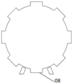
After the processing before welding is finished, clamping and fixing the cylinder, designing a set of high-precision clamping and positioning clamping tools, wherein the whole set of clamping tools are made of 42CrMo steel and consist of an upper end cover plate 01, a bottom plate 02 and a back plate 03, a blind hole 04 with the same appearance as the cylinder end is processed on the bottom plate 02, a blind hole step 08 corresponding to the surface step of the cylinder is arranged on the blind hole 04, the inner surface size of the blind hole 04 is 0.5mm more than the outer surface size of a cylinder end workpiece, so that the clamping is convenient, the depth of the blind hole 04 is 20mm, the minimum distance from the blind hole 04 to the side edge of the bottom plate 02 is 7mm, the rigidity of the tools is ensured, and the front and back width sizes of the bottom plate 02 are larger than the maximum distance between symmetrical blades of a finished product; a step groove 05 which is contacted with the upper end cover plate 01 is processed above the back plate 03; the upper end cover plate 01 is of a cuboid structure, a positioning boss 06 corresponding to the positioning reversing groove on the upper end face of the cylinder is machined on the lower surface of the upper end cover plate, the width of the positioning boss 06 is 5.9mm, and the height of the positioning boss is 9 mm; a flash guide strip 07 made of Ti-Al high-temperature alloy is arranged between the blind hole step 08 at the position to be welded and two adjacent blind hole steps, and is inserted into an upper end cover plate 01 and a bottom plate 02 of a clamping tool in a pin mode for fixation, the height of the flash guide strip 07 is the same as the integral height of a cylinder end workpiece, the width is 4mm, and the length is 2mm larger than the length of the step; in order to ensure the mechanical property and the high temperature resistance of the flash guide strip, the embodiment is influenced by adopting high-temperature alloy preparation, the flash guide strip is prevented from being damaged during flash extrusion, the guide effect of the flash guide strip is influenced, and other materials meeting the conditions can be adopted for preparing high-strength steel and the like;
(3) linear friction welding
Setting linear friction welding parameters including frequency of 40Hz, amplitude of 4mm, friction pressure of 50MPa, friction time of 5s, upsetting pressure of 80MPa and pressure maintaining time of 15 s; setting welding parameters, performing first blade welding on the step corresponding to the forward direction of the cylinder, and repeating the welding process until all the blades are welded after the first blade is welded;
(4) post weld machining
And after the welding is finished, performing linear cutting and cutting on the welded flash of the integral component.