CN1114101A - Method and device for separating high-concentration nitrogen - Google Patents
Method and device for separating high-concentration nitrogen Download PDFInfo
- Publication number
- CN1114101A CN1114101A CN94190640A CN94190640A CN1114101A CN 1114101 A CN1114101 A CN 1114101A CN 94190640 A CN94190640 A CN 94190640A CN 94190640 A CN94190640 A CN 94190640A CN 1114101 A CN1114101 A CN 1114101A
- Authority
- CN
- China
- Prior art keywords
- adsorption
- tank
- adsorption tank
- balance
- gas
- Prior art date
- Legal status (The legal status is an assumption and is not a legal conclusion. Google has not performed a legal analysis and makes no representation as to the accuracy of the status listed.)
- Granted
Links
Images


Classifications
-
- B—PERFORMING OPERATIONS; TRANSPORTING
- B01—PHYSICAL OR CHEMICAL PROCESSES OR APPARATUS IN GENERAL
- B01D—SEPARATION
- B01D53/00—Separation of gases or vapours; Recovering vapours of volatile solvents from gases; Chemical or biological purification of waste gases, e.g. engine exhaust gases, smoke, fumes, flue gases, aerosols
- B01D53/02—Separation of gases or vapours; Recovering vapours of volatile solvents from gases; Chemical or biological purification of waste gases, e.g. engine exhaust gases, smoke, fumes, flue gases, aerosols by adsorption, e.g. preparative gas chromatography
- B01D53/04—Separation of gases or vapours; Recovering vapours of volatile solvents from gases; Chemical or biological purification of waste gases, e.g. engine exhaust gases, smoke, fumes, flue gases, aerosols by adsorption, e.g. preparative gas chromatography with stationary adsorbents
-
- C—CHEMISTRY; METALLURGY
- C01—INORGANIC CHEMISTRY
- C01B—NON-METALLIC ELEMENTS; COMPOUNDS THEREOF; METALLOIDS OR COMPOUNDS THEREOF NOT COVERED BY SUBCLASS C01C
- C01B21/00—Nitrogen; Compounds thereof
- C01B21/04—Purification or separation of nitrogen
- C01B21/0405—Purification or separation processes
- C01B21/0433—Physical processing only
- C01B21/045—Physical processing only by adsorption in solids
-
- B—PERFORMING OPERATIONS; TRANSPORTING
- B01—PHYSICAL OR CHEMICAL PROCESSES OR APPARATUS IN GENERAL
- B01D—SEPARATION
- B01D53/00—Separation of gases or vapours; Recovering vapours of volatile solvents from gases; Chemical or biological purification of waste gases, e.g. engine exhaust gases, smoke, fumes, flue gases, aerosols
- B01D53/02—Separation of gases or vapours; Recovering vapours of volatile solvents from gases; Chemical or biological purification of waste gases, e.g. engine exhaust gases, smoke, fumes, flue gases, aerosols by adsorption, e.g. preparative gas chromatography
- B01D53/04—Separation of gases or vapours; Recovering vapours of volatile solvents from gases; Chemical or biological purification of waste gases, e.g. engine exhaust gases, smoke, fumes, flue gases, aerosols by adsorption, e.g. preparative gas chromatography with stationary adsorbents
- B01D53/047—Pressure swing adsorption
- B01D53/053—Pressure swing adsorption with storage or buffer vessel
-
- B—PERFORMING OPERATIONS; TRANSPORTING
- B01—PHYSICAL OR CHEMICAL PROCESSES OR APPARATUS IN GENERAL
- B01D—SEPARATION
- B01D2253/00—Adsorbents used in seperation treatment of gases and vapours
- B01D2253/10—Inorganic adsorbents
- B01D2253/116—Molecular sieves other than zeolites
-
- B—PERFORMING OPERATIONS; TRANSPORTING
- B01—PHYSICAL OR CHEMICAL PROCESSES OR APPARATUS IN GENERAL
- B01D—SEPARATION
- B01D2253/00—Adsorbents used in seperation treatment of gases and vapours
- B01D2253/25—Coated, impregnated or composite adsorbents
-
- B—PERFORMING OPERATIONS; TRANSPORTING
- B01—PHYSICAL OR CHEMICAL PROCESSES OR APPARATUS IN GENERAL
- B01D—SEPARATION
- B01D2256/00—Main component in the product gas stream after treatment
- B01D2256/10—Nitrogen
-
- B—PERFORMING OPERATIONS; TRANSPORTING
- B01—PHYSICAL OR CHEMICAL PROCESSES OR APPARATUS IN GENERAL
- B01D—SEPARATION
- B01D2259/00—Type of treatment
- B01D2259/40—Further details for adsorption processes and devices
- B01D2259/40003—Methods relating to valve switching
-
- B—PERFORMING OPERATIONS; TRANSPORTING
- B01—PHYSICAL OR CHEMICAL PROCESSES OR APPARATUS IN GENERAL
- B01D—SEPARATION
- B01D2259/00—Type of treatment
- B01D2259/40—Further details for adsorption processes and devices
- B01D2259/40011—Methods relating to the process cycle in pressure or temperature swing adsorption
- B01D2259/40043—Purging
- B01D2259/4005—Nature of purge gas
- B01D2259/40056—Gases other than recycled product or process gas
-
- B—PERFORMING OPERATIONS; TRANSPORTING
- B01—PHYSICAL OR CHEMICAL PROCESSES OR APPARATUS IN GENERAL
- B01D—SEPARATION
- B01D2259/00—Type of treatment
- B01D2259/40—Further details for adsorption processes and devices
- B01D2259/40011—Methods relating to the process cycle in pressure or temperature swing adsorption
- B01D2259/40058—Number of sequence steps, including sub-steps, per cycle
- B01D2259/4006—Less than four
-
- B—PERFORMING OPERATIONS; TRANSPORTING
- B01—PHYSICAL OR CHEMICAL PROCESSES OR APPARATUS IN GENERAL
- B01D—SEPARATION
- B01D2259/00—Type of treatment
- B01D2259/40—Further details for adsorption processes and devices
- B01D2259/40011—Methods relating to the process cycle in pressure or temperature swing adsorption
- B01D2259/40058—Number of sequence steps, including sub-steps, per cycle
- B01D2259/40062—Four
-
- B—PERFORMING OPERATIONS; TRANSPORTING
- B01—PHYSICAL OR CHEMICAL PROCESSES OR APPARATUS IN GENERAL
- B01D—SEPARATION
- B01D2259/00—Type of treatment
- B01D2259/40—Further details for adsorption processes and devices
- B01D2259/40011—Methods relating to the process cycle in pressure or temperature swing adsorption
- B01D2259/40077—Direction of flow
- B01D2259/40081—Counter-current
-
- B—PERFORMING OPERATIONS; TRANSPORTING
- B01—PHYSICAL OR CHEMICAL PROCESSES OR APPARATUS IN GENERAL
- B01D—SEPARATION
- B01D2259/00—Type of treatment
- B01D2259/40—Further details for adsorption processes and devices
- B01D2259/402—Further details for adsorption processes and devices using two beds
-
- B—PERFORMING OPERATIONS; TRANSPORTING
- B01—PHYSICAL OR CHEMICAL PROCESSES OR APPARATUS IN GENERAL
- B01D—SEPARATION
- B01D53/00—Separation of gases or vapours; Recovering vapours of volatile solvents from gases; Chemical or biological purification of waste gases, e.g. engine exhaust gases, smoke, fumes, flue gases, aerosols
- B01D53/02—Separation of gases or vapours; Recovering vapours of volatile solvents from gases; Chemical or biological purification of waste gases, e.g. engine exhaust gases, smoke, fumes, flue gases, aerosols by adsorption, e.g. preparative gas chromatography
- B01D53/04—Separation of gases or vapours; Recovering vapours of volatile solvents from gases; Chemical or biological purification of waste gases, e.g. engine exhaust gases, smoke, fumes, flue gases, aerosols by adsorption, e.g. preparative gas chromatography with stationary adsorbents
- B01D53/047—Pressure swing adsorption
- B01D53/0473—Rapid pressure swing adsorption
Landscapes
- Chemical & Material Sciences (AREA)
- Analytical Chemistry (AREA)
- Organic Chemistry (AREA)
- Engineering & Computer Science (AREA)
- General Chemical & Material Sciences (AREA)
- Oil, Petroleum & Natural Gas (AREA)
- Chemical Kinetics & Catalysis (AREA)
- Inorganic Chemistry (AREA)
- Separation Of Gases By Adsorption (AREA)
Abstract
一种利用一个装置通过PSA分离高浓度氮气的 方法,该装置包括多个吸附槽(1,2),一个平衡槽(3), 以及一个产品接收槽(4)。该方法的特征在于包括如 下步骤:(a)以预定流速将平衡槽(3)内的高纯度氮气 导入正在进行再生的吸附槽(2)的出口;(b)经压力 平衡管线使两个吸附槽(1,2)的出口相连,同时使两 个吸附槽的入口向大气敞开;(c)在上述步骤(b)之 后,使平衡槽(3)内预定量的高纯度氮气经吸附槽(2) 出口反向流动,该吸附槽将从再生转换为吸附,同时 还通过其入口提供原始气体。
A method for separating high-concentration nitrogen through PSA using a device, the device comprising a plurality of adsorption tanks (1, 2), a balance tank (3), and a product receiving tank (4). The method is characterized in that it includes the following steps: (a) leading the high-purity nitrogen in the balance tank (3) into the outlet of the adsorption tank (2) being regenerated at a predetermined flow rate; (b) making the two adsorption tanks through the pressure balance pipeline The outlets of the grooves (1, 2) are connected, and the inlets of the two adsorption grooves are opened to the atmosphere; (c) after the above step (b), the predetermined amount of high-purity nitrogen in the balance groove (3) is passed through the adsorption groove ( 2) With reverse flow at the outlet, the sorbent will switch from regeneration to adsorption while also supplying raw gas through its inlet.
Description
本发明涉及一种通过变压吸附(PSA)来分离高浓度氮气的方法和装置。更准确地,本发明涉及一种改进的PSA方法和装置来分离高浓度氮气,它能将产品氮气的纯度提高到99.999%。The present invention relates to a method and device for separating high-concentration nitrogen by means of pressure swing adsorption (PSA). More precisely, the present invention relates to an improved PSA method and apparatus for separating high-concentration nitrogen, which can increase the purity of the product nitrogen to 99.999%.
在本说明书中,所称氮纯度是指氮气和氩气之和的含量相对于整个产品气体之比。In this specification, the so-called nitrogen purity refers to the ratio of the sum of nitrogen and argon to the whole product gas.
众所周知作为一种从混合气体,如主要包含氧气和氮气的空气中连续提取高浓度氮气的方法,需要利用一种装置来重复进行吸附和再生(解吸附),该装置包括多个填满作为吸附剂的碳分子筛(CMS)的吸附槽。这种方法利用CMS的氧气吸附能力根据压力而变化的原理。It is well known that as a method of continuously extracting high-concentration nitrogen from a mixed gas such as air mainly containing oxygen and nitrogen, it is necessary to repeatedly perform adsorption and regeneration (desorption) by means of a device comprising a plurality of filled as adsorption The carbon molecular sieve (CMS) adsorption tank of the agent. This method utilizes the principle that the oxygen adsorption capacity of CMS changes according to pressure.
一般地,CMS的氧气吸附能力随压力增加而增加。如果空气在高压下通过填有CMS的吸附槽,空气中的氧气被CMS吸附从而产生高浓度氮气。相反,如果吸附槽在大气压或真空下排气以在吸附槽中产生一个压降,则氧气从CMS中被释放,从而再生CMS。In general, the oxygen adsorption capacity of CMS increases with increasing pressure. If the air passes through the adsorption tank filled with CMS under high pressure, the oxygen in the air is adsorbed by the CMS to produce a high concentration of nitrogen. Conversely, if the adsorption cell is vented at atmospheric pressure or under vacuum to create a pressure drop in the adsorption cell, oxygen is released from the CMS, thereby regenerating the CMS.
在一种用于分离高浓度氮气的多塔式PSA方法中,一个吸附槽进行吸附以产生高浓度氮气体而另一个吸附槽进行再生。因此,通过交替重复这些步骤,就可能实现连续生产高浓度氮气,因为在所有时间内,总有其中一个吸附槽在产生高浓度氮气体。In a multi-column PSA process for separating high-concentration nitrogen, one adsorption tank performs adsorption to generate high-concentration nitrogen gas while the other adsorption tank performs regeneration. Therefore, by repeating these steps alternately, it is possible to realize the continuous production of high-concentration nitrogen gas, because at all times, one of the adsorption tanks is always producing high-concentration nitrogen gas.
基于PSA的氮气分离方法由于能够以相对低廉的费用方便地生产氮气,因而是有益处的。但是,这种方法同通过蒸发液化氮而获得工业用氮的方法相比,其缺点在于难以提高氮气的纯度。迄今人们已作出各种努力试图增加氮气纯度,但是均未获得满意的结果。特别是当使用在大气压下进行再生的简易装置时,所能达到的产品氮气纯度被限制在99.9%之内。PSA-based nitrogen separation methods are advantageous due to their ability to produce nitrogen easily and at relatively low cost. However, this method has a disadvantage in that it is difficult to increase the purity of nitrogen gas as compared with the method of obtaining industrial nitrogen by evaporating liquefied nitrogen. Various attempts have been made so far to increase the purity of nitrogen, but without satisfactory results. Especially when using simple devices for regeneration at atmospheric pressure, the achievable product nitrogen purity is limited to 99.9%.
例如,日本专利公开第5-32087号提出一种氮气分离方法,它通过PSA方法,其中在大气压下进行再生,可以将产品气体的氮气纯度提高到99.9%。这种方法的第一个特征在于高纯度产品氮气在吸附槽在大气压下进行再生时经其出口通过该吸附槽。第二个特征在于,在所谓的压力平衡步骤之后,来自产品接收槽的高纯度氮气在吸附开始之前反向流入吸附槽以便预先加压。For example, Japanese Patent Laid-Open No. 5-32087 proposes a nitrogen separation method which can increase the nitrogen purity of the product gas to 99.9% by the PSA method in which regeneration is performed at atmospheric pressure. A first feature of this method is that high purity product nitrogen is passed through the adsorption cell through its outlet while the adsorption cell is being regenerated at atmospheric pressure. The second feature is that, after the so-called pressure equalization step, high-purity nitrogen from the product receiving tank flows back into the adsorption tank for pre-pressurization before the adsorption starts.
上述第一个特征,其中高纯度氮气通过正在进行再生的吸附槽,是传统公知的一种用于提高CMS再生效率的办法。上述第二个特征是在无法进行漂洗而施加真空进行再生时,传统公知的一种提高产品气体纯度的办法。上述日本专利公报提议的方法依赖于这些已知特征的结合以便在PSA氮气分离中额外增加氮气的纯度。但是,如前所述,即使采用了上述日本专利公报所公开的方法,产品氮的纯度仍然被限制在99.9%之内。The first feature above, wherein high purity nitrogen is passed through the adsorption tank being regenerated, is a conventionally known approach for increasing the efficiency of CMS regeneration. The above-mentioned second feature is a conventionally known method of increasing the purity of the product gas when rinsing is not possible and vacuum is applied for regeneration. The method proposed in the above-mentioned Japanese patent publication relies on the combination of these known features in order to additionally increase the purity of nitrogen in the PSA nitrogen separation. However, as mentioned above, even if the method disclosed in the above-mentioned Japanese Patent Gazette is adopted, the purity of the nitrogen product is still limited to 99.9%.
因此,本发明的一个目的就是提供一种分离氮气的方法和装置,该方法和装置能够通过相对简易的PSA,其中再生是在大气压下进行的,将氮气纯度提高到99.999%。Therefore, it is an object of the present invention to provide a method and apparatus for separating nitrogen which can improve the purity of nitrogen to 99.999% by a relatively simple PSA, wherein the regeneration is carried out at atmospheric pressure.
根据本发明的第一个方面,通过PSA提供一种分离高浓度氮气的装置,它包括:多个填有碳分子筛的吸附槽;一个与每个吸附槽的出口可断续相连的具有预定容量的产品接收槽;一个在这些吸附槽的出口之间可断续相连的压力平衡管线;用于选择地向上述每个吸附槽入口提供原始气体的原始气体提供装置;以及用于选择地从上述每个吸附槽的入口向大气压部排泄废气的排气装置;其特征在于;在上述每个吸附槽的出口和产品接收槽之间有一个具有预定容量的平衡槽;该平衡槽经止回阀与产品接收槽相连;并且该平衡槽通过一个设有一个止回阀和节流装置的清洗管线(rinse line)与上述每个吸附槽的出口相连。According to a first aspect of the present invention, a device for separating high-concentration nitrogen is provided by PSA, which includes: a plurality of adsorption tanks filled with carbon molecular sieves; a product receiving tank; a pressure equalization line intermittently connected between the outlets of these adsorption tanks; a raw gas supply device for selectively supplying raw gas to the inlet of each of the above-mentioned adsorption tanks; and a device for selectively supplying raw gas from the above-mentioned The inlet of each adsorption tank discharges waste gas to the atmospheric pressure exhaust device; it is characterized in that there is a balance tank with a predetermined capacity between the outlet of each adsorption tank and the product receiving tank; the balance tank passes through a check valve Be connected with product receiving tank; And this balance tank is connected with the outlet of above-mentioned each adsorption tank through a cleaning pipeline (rinse line) that is provided with a check valve and throttling device.
上述高浓度氮气分离装置与典型的先有技术中的多塔式气体分离PSA装置的区别在于:高纯度产品气体单独储存在通过一个止回阀而相互连接的平衡槽和产品接收槽中;以及提供清洗管线使来自平衡槽的高纯度产品气体通向上述每个吸附槽的出口。由于清洗管线仅有一个止回阀和节流装置,只要上述每个吸附槽的压力低于平衡槽的压力,总会有气体流动,从而不但在再生步骤而且在压力平衡步骤时显著增加氮气纯度。The difference between the above-mentioned high-concentration nitrogen separation device and the typical multi-tower gas separation PSA device in the prior art is that the high-purity product gas is stored separately in the balance tank and the product receiving tank connected to each other through a check valve; and A purge line is provided to direct the high purity product gas from the balance tank to the outlet of each of the aforementioned adsorption tanks. Since the purge line has only one check valve and throttling device, as long as the pressure of each adsorption tank mentioned above is lower than the pressure of the balance tank, there will always be gas flow, thereby significantly increasing the nitrogen purity not only in the regeneration step but also in the pressure balance step .
提供平衡槽的另一个目的在于稳定压力。传统上由于大量的来自产品接收槽的产品氮气可以反向直接流入一个吸附槽以便清洗,在产品接收槽内的压力波动很大,其结果是除了使之难以维持稳定的供给压力外,也对PSA操作本身产生不利影响。虽然这个问题可以通过增加产品接收槽的容量而得到克服,但是这个解决办法的缺点是在驱动装置之后启动期的延长。本发明人通过提供一个平衡槽解决了这一难题,同时也发现如果平衡槽的容量设定在0.25-2.5倍于每个吸附器的容量时即能获得最佳结果。Another purpose of providing a balance tank is to stabilize the pressure. Traditionally, since a large amount of product nitrogen from the product receiving tank can be reversed and directly flowed into an adsorption tank for cleaning, the pressure in the product receiving tank fluctuates greatly. The result is that besides making it difficult to maintain a stable supply pressure, it is also difficult The PSA operation itself is adversely affected. Although this problem can be overcome by increasing the capacity of the product receiving trough, this solution has the disadvantage of a prolonged start-up period after the drive. The present inventors solved this problem by providing a balance tank, and also found that the best results can be obtained if the capacity of the balance tank is set at 0.25-2.5 times the capacity of each adsorber.
根据本发明的第一个实施例,在上述每个吸附槽的出口与平衡槽之间的产品管线以及压力平衡管线分别提供有一个单独的开关阀。原始气体提供装置包括一个用于选择地向上述每个吸附槽的入口提供原始气体的开关阀。排气装置也包括一个用于有选择地从上述每个吸附槽的入口排放废气的开关阀。According to the first embodiment of the present invention, the product pipeline and the pressure balance pipeline between the outlet of each adsorption tank and the balance tank are respectively provided with a separate on-off valve. The raw gas supply device includes a switch valve for selectively supplying raw gas to the inlet of each of the adsorption tanks. The exhaust means also includes an on-off valve for selectively exhausting exhaust gas from the inlet of each of the aforementioned adsorption tanks.
根据本发明的第二个实施例,原始气体提供装置及排气装置包括一个公共滑阀,滑阀的切换导致有选择地向上述每个吸附槽的入口提供原始气体以及有选择地从上述每个吸附槽的入口排放废气。类似地,在上述每个吸附槽的出口与平衡槽之间的产品管线以及压力平衡管线设有一个公共滑阀,并且产品气体管线和压力平衡管线根据滑阀的切换而被打开和关闭。根据这样地安排,仅须控制二个滑阀的操作,从而可以简化管路系统和控制系统以便在便于维修的同时降低装置的尺寸和费用。According to the second embodiment of the present invention, the original gas supply device and the exhaust device include a common slide valve, the switching of the slide valve causes the original gas to be selectively supplied to the inlet of each of the above-mentioned adsorption tanks and selectively supplied from each of the above-mentioned Exhaust gas is discharged from the inlet of each adsorption tank. Similarly, a common slide valve is provided in the product line and pressure balance line between the outlet of each adsorption tank and the balance tank, and the product gas line and pressure balance line are opened and closed according to the switching of the slide valve. According to this arrangement, it is only necessary to control the operation of the two slide valves, so that the piping system and the control system can be simplified to reduce the size and cost of the apparatus while facilitating maintenance.
根据本发明的第二个方面,提供一种从主要包括氮气和氧气的原始气体生产纯度为95-99.999%的高浓度氮气的方法,该方法利用包括多个填有碳分子筛的吸附槽,一个平衡槽以及一个经止回阀与平衡槽相连的产品接收槽的高浓度氮气分离装置,通过交替重复加压吸附和大气压下再生而完成。该方法包括如下步骤:According to a second aspect of the present invention, there is provided a method for producing high-concentration nitrogen with a purity of 95-99.999% from a raw gas mainly comprising nitrogen and oxygen, the method utilizing a plurality of adsorption tanks filled with carbon molecular sieves, a The high-concentration nitrogen separation device of the balance tank and a product receiving tank connected to the balance tank through a check valve is completed by alternately repeating pressurized adsorption and regeneration under atmospheric pressure. The method comprises the steps of:
(a)使平衡槽内的高纯度氮气以预定的流速流向正在进行再生的第一个吸附槽的出口;(a) Make the high-purity nitrogen in the balance tank flow to the outlet of the first adsorption tank being regenerated at a predetermined flow rate;
(b)在已完成再生的第一个吸附槽出口与已完成吸附的第二个吸附槽出口之间建立连通之时,同时打开二个吸附槽入口从而使第二个吸附槽内一部分相对较高浓度的氮气流动到第一个吸附槽的出口,同时也使得上述部分氮气将第一吸附槽内的气体从其入口排出去;以及(b) When communication is established between the outlet of the first adsorption tank that has completed regeneration and the outlet of the second adsorption tank that has completed adsorption, the inlets of the two adsorption tanks are opened at the same time so that a part of the second adsorption tank is relatively closed. The high-concentration nitrogen flows to the outlet of the first adsorption tank, and at the same time, the above-mentioned part of the nitrogen gas discharges the gas in the first adsorption tank from its inlet; and
(c)在进行上述步骤(b)预定时间之后,将平衡槽内预定量的高纯度氮气反向通入第一吸附槽的出口,而同时经第一吸附槽的入口提供原始气体以便加压,从而第一吸附槽通过连续提供原始气体而转向吸附过程。(c) After carrying out the above step (b) for a predetermined time, reversely feed a predetermined amount of high-purity nitrogen in the balance tank into the outlet of the first adsorption tank, and at the same time provide raw gas through the inlet of the first adsorption tank for pressurization , so that the first adsorption tank is diverted to the adsorption process by continuously supplying raw gas.
更确切地,在步骤(a)(大气压下再生过程),进行大气压下再生的吸附器被来自平衡槽的高纯度氮气清洗。这意味着该相关的吸附槽在转向吸附步骤时,其吸附效率得到提高。在步骤(b)(压力平衡-释放pressure equalization-release),不仅各个吸附槽的出口互相连接,而且二个吸附槽都经其入口排气。结果是由于二个吸附槽之间的压力差,相对高浓度的氮气从已完成吸附的一个吸附槽流向已完成再生的另一个吸附槽,从而经相关的入口在完成再生之后立即将停留在上述另一个吸附槽内的高浓度氧气彻底排出。此外,由于上述另一个吸附槽的压力低于平衡槽的压力,来自平衡槽的高纯度氮气能流入并充满上述另一个吸附槽的出口区域。More precisely, in step (a) (atmospheric pressure regeneration process), the adsorber undergoing atmospheric pressure regeneration is purged with high-purity nitrogen from the equilibration tank. This means that the adsorption efficiency of the associated adsorption tank is increased when it is turned to the adsorption step. In step (b) (pressure equalization-release), not only the outlets of the individual adsorption tanks are connected to each other, but both adsorption tanks are exhausted through their inlets. The result is that due to the pressure difference between the two adsorption tanks, a relatively high concentration of nitrogen flows from one adsorption tank that has completed adsorption to the other adsorption tank that has completed regeneration, so that it will stay in the above-mentioned adsorption tank immediately after completion of regeneration through the relevant inlet. The high-concentration oxygen in the other adsorption tank is completely discharged. In addition, since the pressure of the above-mentioned another adsorption tank is lower than that of the balance tank, the high-purity nitrogen gas from the balance tank can flow into and fill the outlet area of the above-mentioned another adsorption tank.
最后,在步骤(c)(加压=>吸附),上述另一个已完成再生以转向吸附过程的吸附槽立即从相对较低的压力加压至足以有效完成吸附的压力。由于上述加压是通过来自平衡槽的高纯度氮气的反向流动以及经入口提供原始气体而完成的,并且由于上述另一个吸附槽的出口区域早已在步骤(b)时充满高纯度氮气,因此可以基本上消除混杂气体在随后的吸附步骤中混入产品气体之中。Finally, in step (c) (pressurization => adsorption), the above-mentioned another adsorption tank that has completed regeneration to switch to the adsorption process is immediately pressurized from a relatively low pressure to a pressure sufficient to effectively complete the adsorption. Since the above-mentioned pressurization is completed by the reverse flow of high-purity nitrogen from the balance tank and the supply of raw gas through the inlet, and because the outlet area of the other adsorption tank has already been filled with high-purity nitrogen in step (b), The incorporation of impurity gases into the product gas during the subsequent adsorption step can be substantially eliminated.
通过这种方法,本发明实现了连续生产高纯度(例如99.999%)的高浓度氮气体,它利用了采纳大气压下进行吸附的多塔式高浓度氮气分离PSA装置。这样所能达到的氮气纯度基本上与通过蒸发液化氮所能达到的纯度相等。因此本发明为需要高纯度氮气的工业领域作出了极大的贡献。Through this method, the present invention realizes the continuous production of high-purity (for example, 99.999%) high-concentration nitrogen gas, which utilizes a multi-tower high-concentration nitrogen separation PSA device that adopts adsorption under atmospheric pressure. The nitrogen purity that can be achieved in this way is substantially equal to that which can be achieved by evaporating liquefied nitrogen. Therefore, the present invention greatly contributes to the industrial field requiring high-purity nitrogen.
本发明的最佳实施例将参照附图予以描述,但是这些实施例仅仅作为例子而决非对本发明的限制。Preferred embodiments of the invention will be described with reference to the accompanying drawings, but these embodiments are by way of example only and in no way limit the invention.
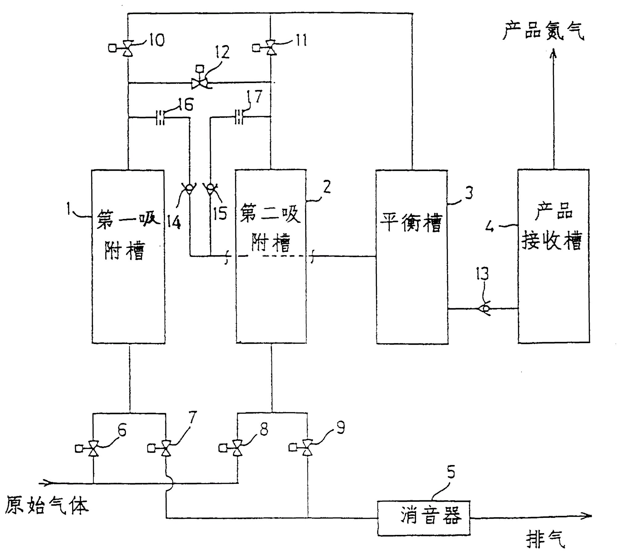
图1是根据本发明第一实施例的高浓度氮气PSA装置的布置示意图;Fig. 1 is a schematic layout diagram of a high-concentration nitrogen PSA device according to a first embodiment of the present invention;
图2是根据本发明第二实施例的高浓度氮气PSA装置的布置示意图;2 is a schematic layout diagram of a high-concentration nitrogen PSA device according to a second embodiment of the present invention;
图3是第二实施例中吸附(解吸附)步骤的示意图;Fig. 3 is the schematic diagram of adsorption (desorption) step in the second embodiment;
图4是第二实施例中压力平衡及释放步骤的示意图;Fig. 4 is a schematic diagram of pressure equalization and release steps in the second embodiment;
图5是根据第二实施例加压和反清洗步骤或解吸附(吸附)步骤的示意图;Fig. 5 is a schematic diagram of pressurization and backwashing steps or desorption (adsorption) steps according to a second embodiment;
图6是用于实施对比较例1的一种装置的布置示意图Fig. 6 is a schematic layout diagram of a device used to implement comparative example 1
本发明的最佳实施例将参照附图进行描述。Preferred embodiments of the present invention will be described with reference to the accompanying drawings.
首先,图1显示了根据本发明第一实施例用于分离高浓度氮气的双槽式PSA装置。First, FIG. 1 shows a double-tank PSA device for separating high-concentration nitrogen gas according to a first embodiment of the present invention.
该第一实施例的装置包括一个第一吸附槽1和一个第二吸附槽2。每个吸附槽1,2均填有碳分子筛(CMS)以形成吸附床。吸附槽1,2具有各自的出口,它们通过设有相应开关阀10,11的产品管线与平衡槽3相连。平衡槽3通过一条设有止回阀13的管线与产品接收槽相连。止回阀13只允许平衡槽3内的气体流向产品接收槽4。产品接收槽内的高纯度氮气经管路适合用于工业用途。The device of the first embodiment includes a
自相应吸附槽1,2的出口向外延伸的产品管线,通过一个设有开关阀12的压力平衡管线,相互连接,连接点距吸附槽较开关阀更近。另外,清洗管线,在其中间分别设有止回阀门14,15和小孔16,17,从平衡槽3向外延伸与分别自吸附槽1,2的出口向外延伸的产品管线相连。每个止回阀门14,15仅允许来自平衡槽3的气体向相应的吸附槽1,2的出口流动,而小孔16,17限制清洗气体的流速。可以在与平衡槽3相连的清洗管线的非支路部分上提供单个小孔,而不必同时在二个清洗管线上分别设置小孔16,17。The product pipelines extending outward from the outlets of the corresponding
每个吸附槽1,2的入口与设有相应开关阀6,8的原始气体提供管线相连。另外,每个吸附槽1,2的入口还与设有相应开关阀7,9的排气管线相连,并且排气管线通过消音器5向大气压外部敞开。The inlet of each
下面,利用上述装置来描述分离高浓度氮气方法的步骤。Next, the steps of the method for separating high-concentration nitrogen will be described using the above-mentioned apparatus.
步骤(a):Step (a):
现在假定第一吸附槽1正在吸附而第二吸附槽2正在再生。在这一假设下,在步骤(a),对于第一吸附槽1,阀6,10打开而阀7关闭。对于第二吸附槽2,阀8,11关闭而阀9打开。另外,在压力平衡管线上的阀12被关闭。主要包括氮气和氧气的原始气体,如空气或类似气体,通过相关的原始气体提供管线和阀6向第一吸附槽1提供,从而第一吸附槽1内的最大压力至少达到5.0kg/cm G(G:gaugepressure表压),例如6.5kg/cm G.原始气体中所含氧气在第一吸附槽1内被吸附,从而高浓度氮气体经相关的产品管线和阀10被导向平衡槽3。在这种情况下,产品接收槽4内的压力变成6.5kg/cm G,而且即使平衡槽3内的压力下降,该压力也由止回阀13保持。Now assume that the
另一方面,由于第二吸附槽2通过相应的排气管线和阀9向大气压外部敞开,第二吸附槽2内的压力降至大气压。由于如此的压力下降,先前被吸附床吸附的氧气被解吸附而排出。结果是第二吸附槽2被再生以便重复吸附。On the other hand, since the
在第二吸附槽2的再生过程中,由于第二吸附槽2内的压力低于平衡槽3内的压力,来自平衡槽3的高纯度氮气经清洗管线被导向第二吸附槽2的出口。其结果,高纯度氮气协助氧气从吸附床上被解吸附,从而提高了再生效率。考虑到高纯度氮气的生产效率以及产量,可以通过小孔17将高纯度氮气流过清洗管线的流速适当设定在低于第一吸附槽1所生产的高纯度氮气总量的范围内。During the regeneration process of the
当第一吸附槽1的吸附床达到吸附极限,将开始下一步骤(b)。When the adsorption bed of the
步骤(b):Step (b):
在步骤(b),每个阀处于下列状态:In step (b), each valve is in the following states:
对于第一吸附槽1,阀6,10关闭而阀7打开。对于第二吸附槽2,阀8,11关闭而阀9打开。另外,压力平衡管线上的阀12是打开的。考虑到从步骤(a)的状态变化,阀6,10由打开转向关闭,阀7,12则由关闭转向打开,而第二吸附槽2的阀8,9,11保持在步骤(a)时同样的状态。结果是每个吸附槽1,2的出口经压力平衡管线及阀12而相互连通,而每个吸附槽1,2的入口经相应的排气管线和阀7,9向大气压外部敞开。For the
在上述阀门转换之后的初始阶段,由于第一吸附槽1内的压力高于第二吸附槽2内的压力,停留在第一吸附槽1的出口处的相对较高浓度的氮气由于二个吸附槽1,2之间的压差而经压力平衡管线和阀12流向第二吸附槽2的出口。其结果是双槽1,2的压力均高于大气压,从而二个吸附槽1,2均须经其相应的入口排气。In the initial stage after the above-mentioned valve switching, because the pressure in the
考虑到第二吸附槽2,在上述步骤(a)之后可能仍停留在其入口区域的相对较高浓度的部分氧气,由于上述气体的运动而引入部分高浓度氮气而经排气管线被清除出去。另外在这种条件下,由于在第二吸附槽2内的压力仍然低于平衡槽3内的压力,高纯度氮气经清洗管线被引到出口,其结果是在第二吸附槽2内的出口区域充满了高纯度氮气。Considering the
考虑到第一吸附槽1,由于其入口通向大气外部,基本上已开始一部分再生,它能达到对再生效率的预期改善。Considering that the
步骤(b)将持续一个预定的时间,之后是下一个步骤(c)。应适当设定步骤(b)的持续时间,从而使第一吸附槽1与第二吸附槽2之间的绝对压力之比处于0.05-0.95之间。Step (b) will last for a predetermined time, followed by the next step (c). The duration of step (b) should be appropriately set so that the absolute pressure ratio between the
步骤(c):Step (c):
与步骤(a)相反,步骤(c)所选定的各个阀的状态应当能使第一吸附槽1进行再生,第二吸附槽2进行吸附。具体地讲,对于第一吸附槽1,阀6,10关闭,阀7打开。对于第二吸附槽2,阀8,11打开,阀9关闭。另外,在压力平衡管线上的阀12是关闭的。考虑到从步骤(b)的状态变化,阀12由″开″转向″关″,阀8,11由″关″转向″开″,并且阀9由″开″转向″关″,而用于第一吸附槽1的阀6,7,10保持它们在步骤(b)时的状态。Contrary to step (a), the state of each valve selected in step (c) should enable regeneration of the
在上述阀门转换后的初始阶段,由于第二吸附槽2内的压力较低来自平衡槽3的高纯度氮气可以经第二吸附槽的出口反向流过相应的产品管线和阀11,而原始气体也经入口提供从而吸附槽内部压力立即上升至适合于吸附的压力值。In the initial stage after the above-mentioned valve conversion, due to the low pressure in the
高纯度氮气自平衡槽3的反向流速取决于平衡槽3的容量。然而,高纯度氮气反向流速的确定应当使得第二吸附槽2内的压力升高,一旦完成反向流动之后,至少上升到不低于吸附期间最大压力的40%,不高于60%,最好是50-55%。平衡槽3的容量虽然取决于提供原始气体的能力,但最好是每个吸附槽的容量的0.25-2.5倍。另外,高浓度氮气的反向流速与提供原始气体直至完成反向流动时流速之比最好是在1∶2到2∶1的范围内。The reverse flow rate of high-purity nitrogen from the
虽然上述高纯度氮气的反向流动在平衡槽3内造成一个压降,该压降由于位于两个槽3,4之间的止回阀13的插入并不影响产品接收槽4。结果是有可能调整产品接收槽4内的压力波动,从而能够稳定地提供高浓度氮气。Although the above-mentioned reverse flow of high-purity nitrogen causes a pressure drop in the
与高纯度氮气反向流动同时进行的是第二吸附槽2由于经其入口提供原始气体而转向吸附过程。其结果是,高浓度产品氮气经产品管线被送往平衡槽3和产品接收槽4。Simultaneously with the reverse flow of high-purity nitrogen, the
另一方面,第一吸附槽1进行再生,其中来自平衡槽3的高纯度氮气以预定的流速流过清洗管线以提高再生效率(如步骤(a)中针对吸附槽2所述)。此外,由于第一吸附槽1的底部早已在步骤(b)向大气压外部敞开,因此,如前所述,再生也早已开始,从而提高了第一吸附槽1的再生效率。上述方法中的步骤(b)象征性地区别于先有技术中PSA气体分离的压力平衡,并且该步骤(b)对于将氨气纯度提高到99.999%起到极大的作用。具体地讲,几乎所有停留在已完成再生的吸附槽的入口处区域的,并已被解吸附的氧气通过从另一吸附槽的出口经平衡管线送入相对较高浓度的氮气,可以几乎彻底地被排出槽外。这样,妨碍氮气纯度达到99.9%以上的因素即被消除。此外,在步骤(b),相关槽内部的出口处区域充满了经清洗管线提供的高纯度氮气,从而极大地减少了杂质在随后的吸附过程中混入产品气体的可能性。On the other hand, the
另外,在步骤(c),经有关的吸附槽的出口反向传输来自平衡槽3的高纯度氮气,同时经其入口提供原始气体。因此,通过同时经其出口和入口提供高压气体就能够立刻对有关吸附槽加压至一个适当的压力以便进行吸附。In addition, in step (c), the high-purity nitrogen gas from the
如前所述,由于有关吸附槽的出口处区域早已在步骤(b)充满高纯度氮气,该氮气进一步被上述反向流动的高纯度氮气压向入口处。结果是原始气体中的氧气进入产品气体而成为杂质几乎完全不可能。这样,上述方法几乎彻底消除了在由再生转向吸附时很有可能发生的杂质气体进入产品气体的可能性。结果,有可能首次达到99.999%的高纯度。As mentioned above, since the outlet area of the relevant adsorption tank has already been filled with high-purity nitrogen in step (b), the nitrogen is further compressed to the inlet by the above-mentioned reverse flow of high-purity nitrogen. The result is that it is almost impossible for oxygen in the original gas to enter the product gas as an impurity. Thus, the above-described method almost completely eliminates the possibility of impurity gas entering the product gas, which is likely to occur when switching from regeneration to adsorption. As a result, it was possible for the first time to achieve a high purity of 99.999%.
图2至5显示了根据本发明第二实施例用于分离高浓度氮气的双槽式PSA装置。第二实施例与图1所示第一实施例的主要区别如下:第一,根据第一实施例在与相应吸附槽1,2的入口相连的原始气体提供管线上的开关阀6,8以及在与相应吸附槽的入口相连的排气管线上的开关阀7,9,由根据第二实施例具有五个通口P1(1),P1(2),P1(3),P1(4),P1(5)的第一滑阀SV1所取代。2 to 5 show a double-tank PSA device for separating high-concentration nitrogen gas according to a second embodiment of the present invention. The main difference of the second embodiment and the first embodiment shown in Fig. 1 is as follows: first, according to the first embodiment, on-off
第二个区别在于,连接相应吸附槽的出口与平衡槽的产品管线上的开关阀10,11以及压力平衡管线上的开关阀12,由根据第二实施例具有五个通口P2(1),P2(2),P2(3),P2(4),P2(5)的第二滑阀SV2所取代。The second difference is that the on-off
如图2所示,第一滑阀SV1的一侧(第一个四通开关阀)是由与原始气体提供管线相连的第一通口P1(1),和与排气管线相连的第二和第三通口组成。第一滑阀SV1的另一侧设有经管线分别与第一和第二吸附槽1,2的入口相连的第四和第五通口P1(4),P1(5)。上述排气管线,同第一实施例一样,设有消音器5。As shown in Figure 2, one side of the first spool valve SV1 (the first four-way switch valve) is composed of the first port P1(1) connected to the original gas supply line, and the second port connected to the exhaust line. and the third port. The other side of the first spool valve SV1 is provided with fourth and fifth ports P1(4), P1(5) respectively connected to the inlets of the first and
在第一滑阀SV1中,一个与图1中数字6相对应的开关阀设在第一通口P1(1)和第四通口P1(4)之间,而与图1中数字8相对应的开关阀设在第一通口P1(1)和第五通口P1(5)之间。另外,与图1中数字7相对应的一个开关阀设在第二通口P1(2)和第四通口P1(4)之间,而与图1中数字9相对应的一个开关阀设在第三通口P1(3)和第五通口P1(5)之间。In the first spool valve SV1, an on-off valve corresponding to the number 6 in Fig. 1 is set between the first port P1(1) and the fourth port P1(4), and is corresponding to the
另一方面,第二滑阀SV2的一侧设有分别与自第一吸附槽1和第二吸附槽2的出口向外延伸的产品气体管线相连的第一和第二通口P2(1),P2(2)。另外,第二滑阀SV2的另一侧设有经管线与平衡槽3相连的第三通口P2(3),和经压力平衡管线相互连接的第四和第五通口P2(4),P2(5)。类似于第一实施例,清洗管线支路自平衡槽3向外延伸,与相应的产品气体管线会合,并且设有相应的止回阀14,15。另外,清洗管线具有一个设有单一小孔16′的非支路部分。在这方面,第二实施例也不同于图1中的第一实施例(其中设有两个小孔16,17)。On the other hand, one side of the second spool valve SV2 is provided with first and second ports P2(1) respectively connected to the product gas pipelines extending outward from the outlets of the
在第二滑阀SV2中,一个与图1中数字10相对应的开关阀设在第一通口P2(1)和第三通口P2(3)之间,而与图1中数字11相对应的开关阀设在第二通口P2(2)和第三通口P2(3)之间。另外,与图1中数字12相对应的一个公共开关阀设在第一通口P2(1)和第四通口P2(4)之间,以及第二通口P2(2)和第五通口P2(5)之间。In the second spool valve SV2, an on-off valve corresponding to the
第二实施例的布置在其他方面与图1所示第一实施例类似。第二实施例的装置按如下方式操作,来执行分离高浓度氮气的方法。The arrangement of the second embodiment is otherwise similar to that of the first embodiment shown in FIG. 1 . The apparatus of the second embodiment operates as follows to perform the method of separating high-concentration nitrogen.
步骤(a):Step (a):
现在假设第一吸附槽1正在吸附而第二吸附槽2正在再生。在此假设下,在步骤(a),第一滑阀SV1及第二滑阀SV2分别处于图3所示的状态。原始气体通过第一滑阀SV1的第一通口P1(1)和第四通口P1(4)向第一吸附槽1的入口提供,从而第一吸附槽1内的最大压力至少达到5.0kg/cmG,例如6.5kg/cmG。原始气体中所含氧气在第一吸附槽1内被吸附,从而高浓度氮气体经第二滑阀SV2的第一通口P2(1)和第三通口P2(3)被导向平衡槽3。Now assume that the
另一方面,由于第二吸附槽2的入口经第一滑阀SV1的第五通口P1(5)和第三通口向大气压外部敞开,第二吸附槽2内的压力降至大气压。由于如此的压力下降,先前被吸附床吸附的氧气被解吸附而排出。结果是第二吸附槽2被再生,以用于下次吸附。On the other hand, since the inlet of the
在第二吸附槽2的再生过程中,由于第二吸附槽2内的压力低于平衡槽3内的压力,来自平衡槽3的高纯度氮气经清洗管线被导向第二吸附槽2的出口。其结果,高纯度氮气协助氧气从吸附床上被解吸附,从而提高了再生效率。通过小孔16′可适当调节高纯度氮气流过清洗管线的流速。During the regeneration process of the
当第一吸附槽1的吸附床达到吸附极限,将开始下一步骤(b)。When the adsorption bed of the
步骤(b):Step (b):
在步骤(b),第一滑阀SV1和第二滑阀SV2转向图4所示相应的状态。结果是每个吸附槽1,2的出口经第二滑阀SV2的第一通口P2(1),第四通口P2(4),第二通口P2(2)和第五通口P2(5),以及压力平衡管线而相互连通,而每个吸附槽1,2的入口经第一滑阀SV1的第二通口P1(2),第四通口P1(4),第三通口P1(3)和第五通口P1(5),以及相应的排气管线向大气压外部敞开。In step (b), the first spool valve SV1 and the second spool valve SV2 are turned to the corresponding states shown in FIG. 4 . The result is that the outlet of each
在上述相应滑阀SV1,SV2转换之后的初始阶段,由于第一吸附槽1内的压力高于第二吸附槽2内的压力,停留在第一吸附槽1的出口侧区域的相对较高浓度的氮气由于二个吸附槽1,2之间的压差而经压力平衡管线流向第二吸附槽2的出口。其结果是两个吸附槽1,2的压力均高于大气压,从而二个吸附槽1,2均须经其相应的入口排气。In the initial stage after the above-mentioned corresponding spool valves SV1, SV2 switch, since the pressure in the
考虑到第二吸附槽2,在上述步骤(a)之后可能仍停留在其入口侧区域的相对较高浓度的部分氧气,由于上述气体的运动而引入部分高浓度氮气而经排气管线被清除出去。另外在这种条件下,由于在第二吸附槽2内的压力仍然低于平衡槽3内的压力,高纯度氮气经清洗管线被引到出口,其结果是在第二吸附槽2内的出口侧区域充满了高纯度氮气。Considering the
考虑到第一吸附槽1,由于其入口通向大气外部,基本上已开始一部分再生,它能达到对再生效率的预期改善。Considering that the
步骤(b)将持续一个预定的时间,之后是下一个步骤(c)。应适当设定步骤(b)的持续时间,从而使第一吸附槽1与第二吸附槽2之间的绝对压力之比处于0.05-0.95之间。Step (b) will last for a predetermined time, followed by the next step (c). The duration of step (b) should be appropriately set so that the absolute pressure ratio between the
步骤(c):Step (c):
与步骤(a)相反,如图5所示,步骤(c)所选定的相应滑阀SV1,SV2的状态应当能使第一吸附槽1进行再生,第二吸附槽2进行吸附。Contrary to step (a), as shown in FIG. 5 , the states of the corresponding slide valves SV1 and SV2 selected in step (c) should enable regeneration of the
在上述滑阀SV1,SV2转换后的初始阶段,由于第二吸附槽2内的压力较低,来自平衡槽3的高纯度氮气可以经相应的产品气体管线反向流入第二吸附槽的出口,而原始气体也经入口提供从而吸附槽内部压力立即上升至适合于吸附的压力值。高纯度氮气自平衡槽3的反向流速取决于平衡槽3的容量。In the initial stage after the above-mentioned spool valve SV1 and SV2 are switched, due to the low pressure in the
与高纯度氮气反向流动同时进行的是第二吸附槽2由于经其入口提供原始气体而转向吸附过程。高浓度产品氮气经产品管线被送往平衡槽3和产品接收槽4。Simultaneously with the reverse flow of high-purity nitrogen, the
另一方面,如步骤(a)中针对吸附槽2所述,第一吸附槽1进行再生,其中来自平衡槽3的高纯度氮气以预定的流速流过清洗管线以提高再生效率。此外,由于第一吸附槽1的底部早已在步骤(b)向大气压外部敞开,因此,如前所述,一部分再生也早已开始,从而提高了第一吸附槽1的再生效率。On the other hand, as described for the
这样,图2-5所示的第二实施例能够进行同第一实施例基本相同的运行,而提供极高纯度的高浓度氮气。特别地,根据第二实施例,只须对两个滑阀SV1,SV2进行转换操作,从而该装置,包括相关的管路,均可极大地简化以利于控制和维护。Thus, the second embodiment shown in Figures 2-5 is capable of performing substantially the same operation as the first embodiment, while providing highly concentrated nitrogen of extremely high purity. In particular, according to the second embodiment, only two spool valves SV1, SV2 need to be switched over, so that the device, including the associated piping, can be greatly simplified for control and maintenance.
下面给出一个更具体的实例和对比实例。A more specific example and comparative example are given below.
[实例1][instance 1]
在实例1中利用一种如图1所示的高浓度气体分离PSA装置。该装置包括两个吸附槽1,2;一个平衡槽3和一个产品接收槽4。两个吸附槽1,2均填有CMS,并且平衡槽3的容量与每个吸附槽1,2的容量相同。空气作为原始气体,并进行吸附以达到6.5kg/cmG的最大压力。进行为80秒的PSA循环,它包含一个包括清洗高纯度氮气的大气压再生步骤,一个压力平衡-释放步骤,以及一个加压步骤和随后的吸附步骤。In Example 1, a high-concentration gas separation PSA device as shown in FIG. 1 is utilized. The device comprises two
在压力平衡-释放步骤,第一吸附槽1已完成吸附步骤,而第二吸附槽2已完成大气压再生步骤。阀门12和阀7,9打开以便第一吸附槽1内所含的部分气体通过利用压差经压力平衡管线流向第二吸附槽2的出口,同时也将两个吸附槽从它们各自的入口经排气管线而排空。在该步骤中,由于两个吸附槽内的压力低于平衡槽的压力,来自平衡槽的高纯度氮气经清洗管线被引入并充满相应吸附槽的出口侧内部区域。该步骤所需时间设定为1.5秒。In the pressure balance-releasing step, the
在加压步骤,在先前压力平衡步骤已接收氮气的第二吸附槽2的内部压力,通过经阀8提供空气而升至4.6kg/cmG,同时使来自平衡槽3的高纯度氮气反向通过。随后转向吸附步骤从而结束加压步骤。空气流速与反向通过的高纯度氮气流速之比为3∶2。另一方面,第一吸附槽1转向大气再生步骤。在加压步骤中,平衡槽3的压力在6.5-4.6kg/cmG的范围内波动,而产品接收槽内的压力波动保持在6.5-6.3kg/cmG。In the pressurization step, the internal pressure of the
考虑到质量,实例1中所获取的高浓度气体中残留氧气的浓度为5ppm(氮气纯度为99.9995%),并且在大约-80℃的大气露点时是稳定的。该高浓度气体的生产速度为10Nm/H(N表示标准状态)。Considering the quality, the concentration of residual oxygen in the high-concentration gas obtained in Example 1 is 5 ppm (purity of nitrogen is 99.9995%), and it is stable at the atmospheric dew point of about -80°C. The production rate of this high-concentration gas is 10 Nm/H (N represents the standard state).
需要补充的是,当使用图2-5所示的装置进行类似的操作时,也可以得到一个类似的结果。What needs to be added is that a similar result can also be obtained when using the device shown in Fig. 2-5 to perform similar operations.
[对比例1][Comparative Example 1]
同本发明相比,图6所示装置是用于进行典型的利用PSA分离高浓度气体的传统方法,其中,在大气压下进行再生。图6的装置与图1所示第一实施例的区别仅在于平衡槽及其相关部件被省略,并且提供分别设有开关阀12a,12b的上压力平衡管线和下压力平衡管线。在压力平衡步骤,仅仅开关阀12a,12b打开,其余所有阀门均关闭。In contrast to the present invention, the apparatus shown in FIG. 6 is used to perform a typical conventional method of separating high-concentration gases using PSA, wherein regeneration is performed at atmospheric pressure. The difference between the device of FIG. 6 and the first embodiment shown in FIG. 1 is that the balance tank and its related components are omitted, and an upper pressure balance line and a lower pressure balance line respectively provided with on-off
在对比例1中,当高浓度气体以10Nm/H的速度生产时,残留氧气的浓度可达1000ppm(氮气纯度为99.9%)。In Comparative Example 1, when the high-concentration gas was produced at a rate of 10 Nm/H, the concentration of residual oxygen could reach 1000 ppm (the purity of nitrogen was 99.9%).
[对比例2][Comparative example 2]
在对比例2中,采用的方法与实例1相同,不同之处在于,在完成压力平衡-释放步骤之后,仅仅通过来自平衡槽的高纯度氮气的反向流动而无须提供空气来实现加压。在这步骤中,平衡槽3内的压力波动范围扩大到6.5-3.7kg/cmG并且产品接收槽内的压力波动范围扩大到6.5-6.0kg/cmG。与实例1相比,这种变化的影响在于,当高浓度气体以10Nm/H的速度生产时,氮气的纯度会出现下降,这时残留氧气浓度为100ppm(氮气纯度为99.99%)。In Comparative Example 2, the same method as in Example 1 was used except that pressurization was achieved only by reverse flow of high-purity nitrogen from the balance tank without supplying air after completion of the pressure equalization-release step. In this step, the pressure fluctuation range in the
本发明并不限于上述实施例和实例。特别是用于实施本发明方法的装置并不限于所示的装置。该装置的特征包括在产品接收槽与相应吸附槽之间提供的一个平衡槽,以及提供设有止回阀的清洗管线和在平衡槽与每个吸附槽之间的一个小孔,从而多塔式PSA气体分离装置的典型布置可以适用于其他用途。The present invention is not limited to the above-mentioned embodiments and examples. In particular, the apparatus for carrying out the method according to the invention is not limited to the apparatus shown. The features of the device include a balance tank provided between the product receiving tank and the corresponding adsorption tank, and a purge line provided with a check valve and an orifice between the balance tank and each adsorption tank, so that multiple towers The typical arrangement of the type PSA gas separation unit can be adapted for other purposes.
另外,高浓度气体达到99.999%的纯度并非本发明的一个基本要求。将高浓度气体的纯粹提高到99.999%仅仅是本发明的一个长处,但是,根据设定的工作状况,氮气纯度可以低于99.999%。本发明重要的一点在于它将生产高浓度气体的纯度范围向更高的水准扩展。因此,任何包括在所附权利要求书中所列步骤的方法都属于本发明的技术范畴之内。In addition, 99.999% purity of the high-concentration gas is not an essential requirement of the present invention. Raising the purity of high-concentration gas to 99.999% is only one advantage of the present invention, however, according to the set working conditions, the purity of nitrogen gas can be lower than 99.999%. An important aspect of the present invention is that it extends the purity range for the production of high concentration gases to higher levels. Therefore, any method including the steps listed in the appended claims falls within the technical scope of the present invention.
Claims (13)
Applications Claiming Priority (4)
| Application Number | Priority Date | Filing Date | Title |
|---|---|---|---|
| JP184975/93 | 1993-07-27 | ||
| JP18497593 | 1993-07-27 | ||
| JP265259/93 | 1993-10-22 | ||
| JP26525993A JP3450885B2 (en) | 1993-07-27 | 1993-10-22 | Method and apparatus for separating nitrogen-enriched gas |
Publications (2)
| Publication Number | Publication Date |
|---|---|
| CN1114101A true CN1114101A (en) | 1995-12-27 |
| CN1037751C CN1037751C (en) | 1998-03-18 |
Family
ID=26502822
Family Applications (1)
| Application Number | Title | Priority Date | Filing Date |
|---|---|---|---|
| CN94190640A Expired - Lifetime CN1037751C (en) | 1993-07-27 | 1994-07-22 | Method and device for separating high-concentration nitrogen |
Country Status (10)
| Country | Link |
|---|---|
| US (1) | US5505765A (en) |
| EP (1) | EP0663229B1 (en) |
| JP (1) | JP3450885B2 (en) |
| KR (1) | KR0165005B1 (en) |
| CN (1) | CN1037751C (en) |
| AU (1) | AU666448B2 (en) |
| CA (1) | CA2145272C (en) |
| DE (1) | DE69418996T2 (en) |
| TW (1) | TW310311B (en) |
| WO (1) | WO1995003873A1 (en) |
Cited By (3)
| Publication number | Priority date | Publication date | Assignee | Title |
|---|---|---|---|---|
| CN1095387C (en) * | 1999-05-18 | 2002-12-04 | 天津大学 | High efficiency flexible variable-pressure adsorption technology |
| CN102009963A (en) * | 2010-09-30 | 2011-04-13 | 中国舰船研究设计中心 | High-purity nitrogen preparing method and device |
| CN102600698A (en) * | 2012-03-16 | 2012-07-25 | 浙江勤策空分设备有限公司 | Variable-pressure absorption system and control method of variable-pressure absorption system |
Families Citing this family (27)
| Publication number | Priority date | Publication date | Assignee | Title |
|---|---|---|---|---|
| FR2755875B1 (en) * | 1996-11-15 | 1999-01-29 | Air Liquide | PROCESS AND INSTALLATION FOR SEPARATION OF GAS MIXTURES BY ADSORPTION AT VARIATION OF PRESSURE |
| US5735938A (en) * | 1997-01-15 | 1998-04-07 | Praxair Technology, Inc. | Method for production of nitrogen using oxygen selective adsorbents |
| IT1293118B1 (en) * | 1997-06-06 | 1999-02-11 | Italfilo Di Milli Ottavio & C | PROCESS AND PLANT FOR THE PRODUCTION OF NITROGEN |
| FR2764205B1 (en) * | 1997-06-09 | 1999-07-16 | Air Liquide | PSA DEVICE AND METHOD FOR SEPARATING A GASEOUS MIXTURE |
| US5961694A (en) * | 1997-06-09 | 1999-10-05 | L'air Liquide, Societe Anonyme Pour L'etude Et L'exploitation Des Procedes Georges Claude | Apparatus and process for the separation of gas mixtures by pressure swing adsorption |
| US6048384A (en) * | 1997-12-09 | 2000-04-11 | Smolarek; James | PSA process and system using simultaneous top and bottom evacuation of absorbent bed |
| US6007606A (en) * | 1997-12-09 | 1999-12-28 | Praxair Technology, Inc. | PSA process and system |
| FR2776941B1 (en) | 1998-04-07 | 2000-05-05 | Air Liquide | PROCESS AND UNIT FOR OXYGEN PRODUCTION BY ADSORPTION WITH SHORT CYCLE |
| US6096115A (en) * | 1998-11-25 | 2000-08-01 | Air Products And Chemicals, Inc. | Pressure swing adsorption process and system utilizing two product storage tanks |
| EP1018359A3 (en) * | 1998-11-25 | 2002-09-04 | Air Products And Chemicals, Inc. | Pressure swing adsorption process and system with product storage tank(s) |
| US6183538B1 (en) * | 1999-02-09 | 2001-02-06 | Air Products And Chemicals, Inc. | Pressure swing adsorption gas flow control method and system |
| JP3524527B2 (en) * | 2001-09-05 | 2004-05-10 | 日本酸素株式会社 | Adsorbent and method and apparatus for producing nitrogen using the same |
| US6607100B2 (en) * | 2001-11-26 | 2003-08-19 | Vin Valet, Inc. | Wine or champagne preservation and dispensing apparatus |
| US7022283B2 (en) * | 2001-11-26 | 2006-04-04 | Vin Valet, Inc. | Apparatus and method for preserving collectible items |
| DE10226485A1 (en) * | 2002-06-14 | 2005-06-23 | Infineon Technologies Ag | Semiconductor memory with address decoding unit |
| US6712876B2 (en) * | 2002-08-27 | 2004-03-30 | Litton Systems, Inc. | Oxygen concentrator system with altitude compensation |
| US6712877B2 (en) * | 2002-08-27 | 2004-03-30 | Litton Systems, Inc. | Oxygen concentrator system |
| FR2868145B1 (en) * | 2004-03-26 | 2006-06-30 | Air Liquide | FLUID DISPENSING VALVE AND USE FOR AIR SUPPLY ENRICHED TO OCCUPANTS OF AN AIRCRAFT |
| US20060278078A1 (en) * | 2005-05-25 | 2006-12-14 | Thorstein Holt | Methods and systems for generation of gases |
| JP2010075778A (en) * | 2008-09-24 | 2010-04-08 | Kofurotsuku Kk | Pressure swing adsorption device |
| KR20110076542A (en) * | 2009-12-29 | 2011-07-06 | 서강대학교산학협력단 | High efficiency gas concentrator and control method |
| UA99005C2 (en) * | 2010-09-30 | 2012-07-10 | Общество с ограниченной ответственностью "Сумская-промышленная-компания" | Block for drying high pressure natural gas |
| CN103406004A (en) * | 2013-07-09 | 2013-11-27 | 内蒙古鄂尔多斯联合化工有限公司 | Molecular sieve drying and dehydration method by using synthetic ammonia process |
| US11192060B2 (en) | 2016-07-25 | 2021-12-07 | Jdl Tech Usa Llc | Air separators and related methods |
| CN106477537A (en) * | 2016-11-01 | 2017-03-08 | 北京福瑞通科技有限公司 | A kind of air-conditioned cold store nitrogen making machine and its method for producing nitrogen |
| US11058986B2 (en) * | 2019-01-09 | 2021-07-13 | Bining Holdings Ltd. | Medical gas production system with gas recycling |
| CN116236880B (en) * | 2022-12-30 | 2025-09-16 | 佳业科技(东台)有限公司 | PSA nitrogen making machine |
Family Cites Families (29)
| Publication number | Priority date | Publication date | Assignee | Title |
|---|---|---|---|---|
| US3080693A (en) * | 1958-10-29 | 1963-03-12 | Westinghouse Air Brake Co | Automatic cleaning apparatus for filters in compressed air systems |
| US3399510A (en) * | 1966-05-25 | 1968-09-03 | Air Technologies Inc | Process and apparatus for dehydrating compressed gas |
| US3430418A (en) * | 1967-08-09 | 1969-03-04 | Union Carbide Corp | Selective adsorption process |
| US3564816A (en) * | 1968-12-30 | 1971-02-23 | Union Carbide Corp | Selective adsorption process |
| US3636679A (en) * | 1971-01-04 | 1972-01-25 | Union Carbide Corp | Selective adsorption gas separation process |
| US3738087A (en) * | 1971-07-01 | 1973-06-12 | Union Carbide Corp | Selective adsorption gas separation process |
| DE2260872A1 (en) * | 1972-12-13 | 1974-06-27 | Babcock & Wilcox Ag | METHOD OF GENERATING NITROGEN FOR USE AS AN INERT GAS AND DEVICE FOR USE |
| US4440548A (en) * | 1982-04-19 | 1984-04-03 | Calgon Carbon Corporation | Pressure swing absorption system |
| JPS598605A (en) * | 1982-07-07 | 1984-01-17 | Osaka Oxgen Ind Ltd | Concentration of nitrogen |
| GB2152834B (en) * | 1983-07-23 | 1987-01-28 | Derek Edward Ward | Producing nitrogen from air |
| US4561865A (en) * | 1983-11-01 | 1985-12-31 | Greene & Kellogg, Inc. | Single bed pressure swing adsorption gas separation system |
| CA1250532A (en) * | 1983-11-01 | 1989-02-28 | Norman R. Mccombs | Single bed pressure swing adsorption gas separation system |
| GB8421962D0 (en) * | 1984-08-30 | 1984-10-03 | Boc Group Plc | Separation of gaseous mixture |
| JPS6393322A (en) * | 1986-10-08 | 1988-04-23 | Marutani Kakoki Kk | Switchover method for towers of adsorption device |
| US4725293A (en) * | 1986-11-03 | 1988-02-16 | The Boc Group, Inc. | Automatic control for Pressure Swing Adsorption system |
| JPS6441085A (en) * | 1987-08-05 | 1989-02-13 | Toshiba Corp | Sheet paper processor |
| JPH0226609A (en) * | 1988-07-14 | 1990-01-29 | Kobe Steel Ltd | Production and device for highly pure oxygen by pressure swing adsorption process |
| JPH0230607A (en) * | 1988-07-20 | 1990-02-01 | Kobe Steel Ltd | Production of highly pure nitrogen |
| JP2602072B2 (en) * | 1988-08-22 | 1997-04-23 | 日本電信電話株式会社 | Radio paging device |
| DE3829584A1 (en) * | 1988-09-01 | 1990-03-08 | Bayer Ag | SEPARATION OF GAS MIXTURES BY VACUUM SWING ADSORPTION IN A TWO-ADSORBER SYSTEM |
| EP0380723B1 (en) * | 1989-02-01 | 1994-04-06 | Kuraray Chemical Co., Ltd. | Process for separating nitrogen gas by pressure swing adsorption system |
| JPH0691927B2 (en) * | 1989-08-18 | 1994-11-16 | トキコ株式会社 | Gas generator |
| DE69124276T2 (en) * | 1990-03-29 | 1997-05-07 | Boc Group Inc | Process for the production of an oxygen enriched product stream |
| US5176722A (en) * | 1990-06-19 | 1993-01-05 | The Boc Group, Inc. | Pressure swing adsorption method for separating gaseous mixtures |
| JPH0532087A (en) * | 1991-07-26 | 1993-02-09 | Mitsuru Mishima | Novel multilayered communication sheet |
| US5229089A (en) * | 1991-11-06 | 1993-07-20 | The Boc Group, Inc. | Recovery of flammable materials from gas streams |
| JP3215713B2 (en) * | 1992-03-17 | 2001-10-09 | クラレケミカル株式会社 | Nitrogen gas separation method |
| US5441558A (en) * | 1994-08-09 | 1995-08-15 | Air Products And Chemicals, Inc. | High purity nitrogen PSA utilizing controlled internal flows |
| JP3077617B2 (en) * | 1997-01-24 | 2000-08-14 | 日本電気株式会社 | Delay simulator |
-
1993
- 1993-10-22 JP JP26525993A patent/JP3450885B2/en not_active Expired - Fee Related
-
1994
- 1994-07-22 CN CN94190640A patent/CN1037751C/en not_active Expired - Lifetime
- 1994-07-22 AU AU72377/94A patent/AU666448B2/en not_active Ceased
- 1994-07-22 KR KR1019950701172A patent/KR0165005B1/en not_active Expired - Lifetime
- 1994-07-22 EP EP94921806A patent/EP0663229B1/en not_active Expired - Lifetime
- 1994-07-22 WO PCT/JP1994/001217 patent/WO1995003873A1/en not_active Ceased
- 1994-07-22 DE DE69418996T patent/DE69418996T2/en not_active Expired - Lifetime
- 1994-07-22 CA CA002145272A patent/CA2145272C/en not_active Expired - Fee Related
- 1994-07-26 TW TW083106821A patent/TW310311B/zh not_active IP Right Cessation
-
1995
- 1995-03-24 US US08/403,777 patent/US5505765A/en not_active Expired - Lifetime
Cited By (4)
| Publication number | Priority date | Publication date | Assignee | Title |
|---|---|---|---|---|
| CN1095387C (en) * | 1999-05-18 | 2002-12-04 | 天津大学 | High efficiency flexible variable-pressure adsorption technology |
| CN102009963A (en) * | 2010-09-30 | 2011-04-13 | 中国舰船研究设计中心 | High-purity nitrogen preparing method and device |
| CN102009963B (en) * | 2010-09-30 | 2013-03-20 | 中国舰船研究设计中心 | High-purity nitrogen preparing method and device |
| CN102600698A (en) * | 2012-03-16 | 2012-07-25 | 浙江勤策空分设备有限公司 | Variable-pressure absorption system and control method of variable-pressure absorption system |
Also Published As
| Publication number | Publication date |
|---|---|
| JP3450885B2 (en) | 2003-09-29 |
| AU7237794A (en) | 1995-02-28 |
| DE69418996T2 (en) | 2000-03-09 |
| DE69418996D1 (en) | 1999-07-15 |
| CN1037751C (en) | 1998-03-18 |
| KR950703396A (en) | 1995-09-20 |
| TW310311B (en) | 1997-07-11 |
| CA2145272A1 (en) | 1995-02-09 |
| CA2145272C (en) | 1999-06-15 |
| EP0663229A4 (en) | 1995-12-27 |
| US5505765A (en) | 1996-04-09 |
| JPH0788316A (en) | 1995-04-04 |
| EP0663229A1 (en) | 1995-07-19 |
| KR0165005B1 (en) | 1999-01-15 |
| WO1995003873A1 (en) | 1995-02-09 |
| AU666448B2 (en) | 1996-02-08 |
| EP0663229B1 (en) | 1999-06-09 |
Similar Documents
| Publication | Publication Date | Title |
|---|---|---|
| CN1037751C (en) | Method and device for separating high-concentration nitrogen | |
| CN1044106C (en) | Recovery method of oxygen-enriched gas | |
| CN1062781C (en) | Improved vacuum pressure swing adsorption process | |
| JP3232003B2 (en) | Reflux in pressure swing adsorption method | |
| JP3492869B2 (en) | Single bed pressure swing adsorption method for oxygen recovery from air | |
| JP2744596B2 (en) | Method for selectively separating relatively strong adsorbent components from relatively weak adsorbent components of feed gas mixture | |
| CN101511448B (en) | Vpsa process and enhanced oxygen recovery | |
| CN101340969B (en) | Pressure swing adsorption process for oxygen production | |
| JP3310249B2 (en) | Oxygen production method and apparatus using one adsorber and one blower | |
| US6524370B2 (en) | Oxygen production | |
| CN1267181C (en) | Method and system for separating gas | |
| CN1050767C (en) | High purity nitrogen PSA utilizing controlled internal flows | |
| KR920002081B1 (en) | Improved gas seperation method using pressure swing adsorption | |
| CN1252322A (en) | Variable pressure absorbing method for producing oxygen-enriched gas | |
| JPH08224428A (en) | Continuous method for separating component of gas mixture bymeans of pressure swing adsorption | |
| CN110354637B (en) | Method for enriching easily-adsorbed gas by pressure swing adsorption method | |
| CN1599636A (en) | Pressure swing adsorption process for co-production of nitrogen and oxygen | |
| CN1273375C (en) | Recovery method of concentrated oxygen | |
| CN1077447C (en) | Serial flow pressure swing adsorption process for gas separation | |
| CN1671462A (en) | Target gas separation method | |
| TW587955B (en) | Pressure swing adsorption process with controlled internal depressurization flow | |
| JP3654661B2 (en) | Oxygen generation method by pressure fluctuation adsorption separation method | |
| CN1482937A (en) | Target gas separation method and separation device | |
| EP0529513A2 (en) | Pressure swing adsorption for hydrogen with high productivity | |
| JPS6238281B2 (en) |
Legal Events
| Date | Code | Title | Description |
|---|---|---|---|
| C06 | Publication | ||
| PB01 | Publication | ||
| C10 | Entry into substantive examination | ||
| SE01 | Entry into force of request for substantive examination | ||
| C14 | Grant of patent or utility model | ||
| GR01 | Patent grant | ||
| C17 | Cessation of patent right | ||
| CX01 | Expiry of patent term |
Expiration termination date: 20140722 Granted publication date: 19980318 |