Microwave mixer circuit and use the down converter of this circuit
Technical field
The present invention relates to utilize broadcasting satellite and communication satellite to carry out used microwave mixer circuit in down converter that satellite broadcasting or communications reception use etc., and have the satellite broadcasting of this circuit or the down converter that communications reception is used.
Background technology:
In recent years, satellite broadcasting has welcome its universal phase, in addition, utilize the CS broadcasting of communication satellite among the people also to begin to serve, thereby the chance that directly receives a plurality of satellites in general family increases.The thing followed then requires the miniaturization and the cost degradation of communication antenna.
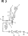
Below utilize Fig. 3 that existing microwave mixer circuit and intermediate frequency amplifier are described.Shown in Figure 3 is the structure of existing microwave mixer circuit.In Fig. 3, the 1st, the microwave signal input part; The 2nd, local oscillator; The 3rd, the band pass filter (hereinafter to be referred as BPF) that makes local oscillation frequency be able to pass through; The 4th, microstrip line (hereinafter to be referred as MSL); The 5th, the diode that frequency conversion is used uses the occasion of Schottky diode (hereinafter to be referred as SBD) in the majority now, and in the following description, this diode adopts SBD5 to represent; The 6th, apply the bias current feeding terminal that bias current is used to SBD5, the 7th, the low pass filter (hereinafter to be referred as LPF) that makes the intermediate wave signal be able to pass through, 8 and 9 is intermediate frequency amplifiers, the 10th, the intermediate-freuqncy signal efferent.
Below describe for the existing microwave mixer circuit that adopts said structure and the operation principle of intermediate frequency amplifier.The microwave signal of the 12GHz frequency band of input microwave signal input part and the oscillation signals according of being supplied with by local oscillator 2 by BPF3 are (for example: 10.678GHz) mix through the SBD5 that is connected with MSL4, be transformed into the intermediate-freuqncy signal of 1GHz frequency band.
In the case, when the oscillation signals according voltage of SBD5 during less than desired value, the conversion loss that produces in frequency conversion process will increase.In order to prevent the increase of this conversion loss, will supply with small bias voltage to the diode that frequency conversion is used.
For such bias voltage is provided, apply the biasing control voltage of regulation to bias current feeding terminal 6.
Intermediate-freuqncy signal by LPF7 is amplified via intermediate frequency amplifier 8 and 9, takes out from intermediate-freuqncy signal efferent 10.
But, in the structure of above-mentioned conventional example, oscillation signals according voltage with each device (for example MESFET) that uses in the local oscillator 2 high frequency characteristics and alignment error etc. always bigger error is arranged.
Therefore, the commutating voltage of the above-mentioned oscillation signals according voltage of SBD5 also produces discrete discrepancy with the deviation that is added in the oscillation signals according voltage on the SBD5.For this reason, although apply certain biasing control voltage to bias current feeding terminal 6, can not make the bias current that flows to SBD5 is desired value, so the phenomenon that discrete discrepancy increases occurs.
Therefore, when producing in a large number, just be difficult to guarantee the performance stipulated.
Summary of the invention
In order to overcome consequent problem, microwave mixer circuit of the present invention applies and the corresponding bias current of oscillation signals according output voltage to SBD5.Like this, microwave mix of the present invention just can lower the discrete discrepancy of the conversion loss of frequency mixer.
That is, microwave mixer circuit has: pull the microwave signal input part that forms with MSL at the insulation end; Anode is connected with the terminal part of above-mentioned MSL, earthed-cathode SBD5 and bias voltage supply circuit.
Above-mentioned bias voltage supply circuit has: apply the bias current feeding terminal of bias voltage and take out the detection terminal of the direct voltage that generates at anode tap to the anode of mixer diode, be added on the bias current feeding terminal of supply bias current according to the direct voltage that is produced by the above-mentioned detection terminal control voltage of will setover.
The invention provides a kind of microwave mixer circuit, it is characterized in that comprising: local-oscillator circuit; The diode that utilizes microwave input signal and carry out frequency translation from the oscillation signals according that above-mentioned local-oscillator circuit is supplied with; Apply the bias current feeding terminal of the biasing control voltage of supplying with bias current to above-mentioned diode; The detection terminal of the direct voltage that detection produces on above-mentioned diode; According to the direct voltage of above-mentioned detection and the comparative result of reference voltage, the biasing supply circuit of voltage is controlled in the above-mentioned biasing that control is supplied with from above-mentioned bias current feeding terminal.
The invention provides a kind of microwave mixer circuit, it is characterized in that comprising: the microwave signal input part; Local-oscillator circuit; A diode, its anode is connected with the terminal part of above-mentioned microwave signal input part, and its minus earth utilizes from the signal of above-mentioned microwave signal input part input with from the oscillation signals according that above-mentioned local-oscillator circuit is supplied with and carries out frequency translation; Apply the bias current feeding terminal of bias current to the anode of above-mentioned diode; The detection terminal of the direct voltage that taking-up produces on the anode of above-mentioned diode; Will with the bias voltage supply circuit that applies to above-mentioned bias current feeding terminal of control voltage of setovering accordingly by the comparative result of direct voltage that detects on the above-mentioned test side and reference voltage.
The invention provides a kind of down converter, it is characterized in that comprising: the microwave signal input part that on microstrip line, forms; Local-oscillator circuit; A diode, its anode is connected with terminal part on the above-mentioned microstrip line, and minus earth utilizes from the signal of above-mentioned microwave signal input part input with from the oscillation signals according that above-mentioned local-oscillator circuit is supplied with and carries out frequency translation; Apply the bias current feeding terminal of bias current to the anode of above-mentioned diode; The detection terminal of the direct voltage that taking-up takes place on above-mentioned anode; Will with the biasing supply circuit of supplying with above-mentioned bias current feeding terminal by the corresponding bias current of the comparative result of direct voltage that takes place on the above-mentioned detection terminal and reference voltage.
The invention provides a kind of down converter, it is characterized in that comprising: the probe that microwave signal is transformed into the TEM ripple;
A plurality of low noise amplifiers; The microstrip line that is connected with low noise amplifier; The diode that is connected with the terminal part of this microstrip line; Supply with the bias current feeding terminal of bias current to above-mentioned diode; The detection terminal of the direct voltage that taking-up takes place on above-mentioned diode.To supply with the bias voltage supply circuit of above-mentioned bias current feeding terminal with the corresponding bias current of the comparative result of direct voltage that on above-mentioned detection terminal, takes place and reference voltage.
Like this, be added on the anode of above-mentioned SBD5 by detecting the direct voltage that obtains from the oscillation signals according output voltage of local oscillator supply, even the oscillation signals according output voltage has discrete discrepancy, also the conversion loss of mixing can be suppressed to be less value.
The objective of the invention is to solve above-mentioned existing problem, low price is provided, microwave mixer circuit that discrete discrepancy is little when producing in a large number and down converter.
Description of drawings
Fig. 1 is the microwave mixer circuit figure among the present invention the 1st embodiment.
Fig. 2 is the circuit diagram that uses the down converter of microwave mixer circuit among the present invention the 2nd embodiment.
Fig. 3 is the circuit diagram of existing microwave mixer.
Embodiment
The 1st embodiment
Shown in Figure 1 is microwave mixer circuit among the 1st embodiment of the present invention.
In Fig. 1, the 1st, the microwave signal input part, the 2nd, local oscillator, the 3rd, the BPF that makes local oscillation frequency be able to pass through, the 4th, MSL, the 5th, SBD5, the 6th, the bias current feeding terminal that provides bias current to use to SBD5, the 7th, the LPF that makes intermediate-freuqncy signal be able to pass through, 8 and 9 is intermediate frequency amplifiers, the 10th, the intermediate-freuqncy signal efferent.The 11st, take out the detection terminal of the direct voltage that SBD5 takes place, the 12nd, the bias voltage supply circuit that constitutes by computing circuit.
Resistance 13 and 14 is used for the service voltage (not shown) is carried out dividing potential drop.Voltage through dividing potential drop is to make the conversion loss of SBD5 become minimum voltage, is added to an end of the input terminal of bias voltage supply circuit as pre-prepd reference voltage.
Below describe for the microwave mixer circuit of said structure and the action of intermediate frequency amplifier.
The microwave signal of the 12GHz frequency band of input microwave signal input part 1 imports MSL4 simultaneously with the oscillation signals according of supplying with from local oscillator 12 by BPF3 (for example 10.678GHz).
On the anode of the SBD5 that is connected with MSL4, generate direct voltage through the direct voltage that over commutation takes place by the direct voltage that takes place by the voltage that applies from bias current feeding terminal 6 with by the oscillation signals according of supplying with by local oscillator 2.The direct voltage of this generation takes out from detection terminal 11 as detecting voltage.
Bias supply circuit 12 should detect voltage and said reference voltage compares, and applies biasing control voltage to bias current feeding terminal 6.
Bias supply circuit 12 becomes the voltage identical with reference voltage through such processing with detecting voltage control.
Therefore, SBD5 just can not be subjected to can realize always good conversion loss from the influence of the discrete discrepancy of the oscillation signals according output voltage of local oscillator 2 supplies.The microwave signal that is transformed into the intermediate-freuqncy signal of 1GHz frequency band by SBD5 is passed through to be amplified to desirable level by intermediate frequency amplifier 8 and 9 after the LPF7, is taken out by intermediate-freuqncy signal efferent 10 then.
The 2nd embodiment
Shown in Figure 2 is the down converter circuit diagram that uses the microwave mix shown in the 1st embodiment of the present invention in the 2nd embodiment of the present invention.
In Fig. 2, the 15th, probe is used for transmission by microstrip line, and the microwave signal of the 12GHz frequency band that satellites transmits is come is transformed into accurate TEM ripple (QUASI TRANSVERSE ELECTROMAGNETICWAVE).16 and 17 is the low noise amplifiers that are made of HEMT low noise elements such as (HIGH ELECTRON MOBILITY TRANSISTOR), the 2nd, local oscillator, the 3rd, the BPF that makes local oscillation frequency be able to pass through, the 4th, MSL, the 5th, SBD5, the 6th, apply the bias current feeding terminal of bias current to SBD5, the 7th, the LPF that makes intermediate-freuqncy signal be able to pass through, 8 and 9 is intermediate frequency amplifiers, the 10th, and the intermediate-freuqncy signal efferent.The 11st, take out the detection terminal of the direct voltage that takes place by SBD5, the 12nd, the bias voltage supply circuit that constitutes by computing circuit.
Resistance 13 and 14 is to be used for the feed voltage (not shown) is carried out the resistance that dividing potential drop is used.Voltage through dividing potential drop is to make the conversion loss of SBD5 become minimum voltage, is added to an end of the input terminal of biasing supply circuit as pre-prepd reference voltage.
The working condition of the down converter of said structure below is described.
Pass through probe 15 transmission by the microwave signal that satellites transmits is come, be transformed into accurate TEM ripple, carry out low noise through low noise amplifier 16 and 17 and amplify via microstrip line.Import MSL4 simultaneously through microwave signal of amplifying and the oscillation signals according of supplying with by BPF3 local oscillator 2 (for example 10.678GHz).
On the anode of the SBD5 that is connected with MSL4, generate direct voltage through the direct voltage that over commutation produces by the direct voltage that produces by the voltage that applies from bias current feeding terminal 6 with by the oscillation signals according that local oscillator 2 is supplied with.The direct voltage of this generation is as detecting voltage 11 taking-ups from the test side.
Biasing supply circuit 12 should detect voltage and said reference voltage compares, and applies biasing control voltage to bias current feeding terminal 6.Biasing supply circuit 12 will detect voltage control to the voltage identical with reference voltage through such processing.
Therefore, SBD5 just can not be subjected to can realize always good conversion loss from the influence of the discrete discrepancy of the oscillation signals according output voltage of local oscillator 2 supplies.The microwave signal that is transformed into 1GHz frequency band intermediate-freuqncy signal by SBD5 is amplified to desirable level by after the LPF7 by intermediate frequency amplifier 8 and 9, is taken out by intermediate-freuqncy signal efferent 10 then.
As mentioned above, the present invention by the additional bias current feeding terminal that on the anode of SBD5, applies bias current, detect at the detection terminal of the direct voltage that takes place on the anode and will supply with the bias current supply circuit of biasing control voltage bias electric current supply terminal accordingly with the direct voltage that on detection terminal, produces, the discrete discrepancy of exporting for the local oscillation of local oscillator can obtain stable properties, thereby can realize low price and small-sized microwave mixer and down converter.