Disclosure of Invention
The application provides an image processing method and device, which are used for guaranteeing that the sizes of an original image and a target image are the same, enabling edge pixels of the target image to be continuous, guaranteeing the stability of the target image and improving the image processing efficiency.
In a first aspect, the present application provides an image processing method, including:
determining at least one first block image in an original image;
performing pixel filling on the edge of the original image to obtain a first intermediate image;
determining at least one second block image in a first intermediate image, wherein the first block image and the second block image are in one-to-one correspondence, and the first block image is located in the center of the corresponding second block image;
and processing at least one second block image to obtain a target image, wherein the target size of the target image is the same as the original size of the original image.
In a possible embodiment, determining at least one first block image in the original image comprises:
according to a preset block size, carrying out block processing on an original image to obtain at least one first block image, wherein overlapping pixels exist in part of the first block image in the at least one first block image.
In one possible embodiment, the original image comprises M rows and N columns of the first block image, M and N being integers greater than or equal to 1, respectively, wherein,
partial image overlap exists between the jth column of first block images and the jth +1 column of first block images in the N columns of first block images, wherein j is an integer from 1 to N-1; or,
partial image overlapping exists between the ith row and the jth first block image in the M rows and the N columns of the first block images and the ith row and the jth +1 first block image, wherein i is an integer from 1 to M, and j is an integer from 1 to N-1.
In a possible implementation, the pixel filling is performed at the edge of the original image, resulting in a first intermediate image, comprising:
adding filling pixels at the edge of the original image to obtain a first intermediate image; the position of the filling pixel is symmetrical to the position of the first pixel in the original image, and the color value of the filling pixel is the same as that of the first pixel.
In a possible implementation, processing the at least one second tile image to obtain the target image includes:
performing image processing on each second block image through a preset block image processing algorithm to obtain at least one third block image;
acquiring the weight, the position and the color value of at least one pixel included in each third block image;
and obtaining a target image according to the weight, the position and the color value of each pixel.
In one possible implementation, obtaining the target image according to the weight, the position and the color value of each pixel comprises:
determining a target color value of each pixel according to the weight and the color value of each pixel;
filling the target color value of each pixel to a corresponding position to obtain a second intermediate image;
and cutting the second intermediate image to obtain a target image.
In a possible implementation, the performing a cutting process on the second intermediate image to obtain the target image includes:
acquiring the position of each pixel in the original image and/or the original size of the original image;
and cutting the second intermediate image according to the position and/or the original size of each pixel in the original image to obtain the target image.
In a second aspect, the present application provides an image processing apparatus comprising: a determination module and a processing module, wherein,
the determining module is used for determining at least one first block image in the original image;
the processing module is used for carrying out pixel filling on the edge of the original image to obtain a first intermediate image;
the determining module is used for determining at least one second block image in the first intermediate image, the first block image and the second block image are in one-to-one correspondence, and the first block image is located at the center position of the corresponding second block image;
the processing module is used for processing at least one second block image to obtain a target image, and the target size of the target image is the same as the original size of the original image.
In a possible implementation, the determining module is specifically configured to:
according to a preset block size, carrying out block processing on an original image to obtain at least one first block image, wherein overlapping pixels exist in part of the first block image in the at least one first block image.
In one possible embodiment, the original image comprises M rows and N columns of the first block image, M and N being integers greater than or equal to 1, respectively, wherein,
partial image overlap exists between the jth column of first block images and the jth +1 column of first block images in the N columns of first block images, wherein j is an integer from 1 to N-1; or,
partial image overlapping exists between the ith row and the jth first block image in the M rows and the N columns of the first block images and the ith row and the jth +1 first block image, wherein i is an integer from 1 to M, and j is an integer from 1 to N-1.
In a possible implementation, the processing module is specifically configured to:
adding filling pixels at the edge of the original image to obtain a first intermediate image; the position of the filling pixel is symmetrical to the position of the first pixel in the original image, and the color value of the filling pixel is the same as that of the first pixel.
In a possible implementation, the processing module is specifically configured to:
performing image processing on each second block image through a preset block image processing algorithm to obtain at least one third block image;
acquiring the weight, the position and the color value of at least one pixel included in each third block image;
and obtaining a target image according to the weight, the position and the color value of each pixel.
In a possible implementation, the processing module is specifically configured to:
determining a target color value of each pixel according to the weight and the color value of each pixel;
filling the target color value of each pixel to a corresponding position to obtain a second intermediate image;
and cutting the second intermediate image to obtain a target image.
In a possible implementation, the processing module is specifically configured to:
acquiring the position of each pixel in the original image and/or the original size of the original image;
and cutting the second intermediate image according to the position and/or the original size of each pixel in the original image to obtain the target image.
In a third aspect, the present application provides an image processing apparatus comprising: a processor and a memory;
the memory stores computer-executable instructions;
the processor executes the computer-executable instructions stored by the memory, causing the processor to perform the image processing method of any of the first aspects.
In a fourth aspect, the present application provides a readable storage medium comprising a program or instructions, which when run on a computer, performs the image processing method of any one of the above first aspects.
The application provides an image processing method and device, and the method comprises the following steps: determining at least one first block image in an original image; performing pixel filling on the edge of the original image to obtain a first intermediate image; determining at least one second block image in the first intermediate image, wherein the first block image and the second block image are in one-to-one correspondence, and the first block image is located in the center of the corresponding second block image; and processing the at least one second block image to obtain a target image, wherein the target size of the target image is the same as the original size of the original image. In the method, the target size of the target image is the same as the original size of the original image, so that the size of the target image is ensured to be the same as that of the original image, and the target image is obtained by processing at least one second block image, so that the edge pixels of the target image are continuous, the stability of the target image is ensured, and the image processing efficiency is improved.
The terms "first," "second," "third," "fourth," and the like in the description and in the claims, as well as in the drawings, if any, are used for distinguishing between similar elements and not necessarily for describing a particular sequential or chronological order. It is to be understood that the data so used is interchangeable under appropriate circumstances such that the embodiments of the invention described herein are, for example, capable of operation in sequences other than those illustrated or otherwise described herein. Furthermore, the terms "comprises," "comprising," and "having," and any variations thereof, are intended to cover a non-exclusive inclusion, such that a process, method, system, article, or apparatus that comprises a list of steps or elements is not necessarily limited to those steps or elements expressly listed, but may include other steps or elements not expressly listed or inherent to such process, method, article, or apparatus.
The technical solution of the present invention will be described in detail below with specific examples. The following several specific embodiments may be combined with each other, and details of the same or similar concepts or processes may not be repeated in some embodiments.
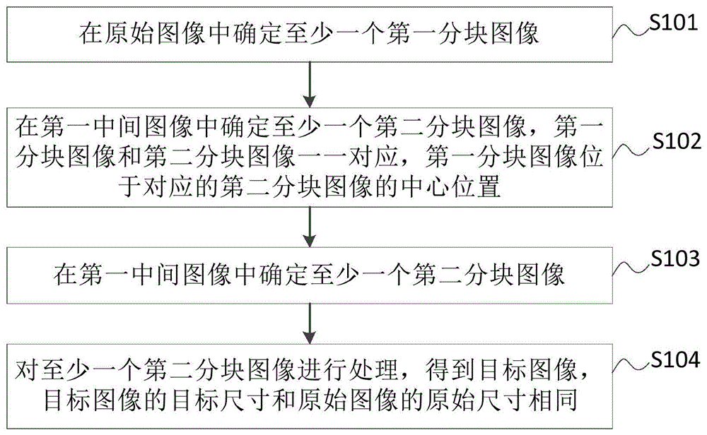
Fig. 1 is a first schematic flow chart of an image processing method provided in the present application. As shown in fig. 1, the image processing method provided by the present embodiment includes:
s101: at least one first block image is determined in the original image.
Alternatively, the execution subject of the image processing method of the present application may be an image capturing apparatus, or may be an image processing device provided in the image capturing apparatus, and the image processing device may be implemented by a combination of software and/or hardware.
The image capturing device may be a camera, a video camera, or a mobile phone with a shooting function, a tablet computer, or the like.
Specifically, the size of each first block image is the same as a preset block size, where the block size may be the size of a preset shape. For example, the predetermined shape may be a square, a rectangle, or the like.
Further, overlapping pixels exist in a part of the first block images in the at least one first block image.
For example, in fig. 5, a first block image includes: the pixels 111, 112, 113, 114, 121, 122, 123, 124, 131, 132, 133, 134, 141, 142, 143, 144, another first block image includes: 114. 211, 212, 214, 124, 221, 222, 224, 324, 231, 232, 224, 424, 241, 232, 244. The pixels 114, 124, 134, and 144 are overlapped pixels of the first block image and the second block image.
S102: and carrying out pixel filling on the edge of the original image to obtain a first intermediate image.
Alternatively, pixels inside the edge of the original image may be filled out of the edge of the original image, thereby forming a first intermediate image, wherein the size of the first intermediate image is larger than the original size of the original image, and the original size is the size of the original image. In particular, reference may be made to the original image and the first intermediate image shown in the embodiment of fig. 5.
S103: and determining at least one second block image in the first intermediate image, wherein the first block image and the second block image are in one-to-one correspondence, and the first block image is positioned in the center position of the corresponding second block image.
Specifically, the corresponding second block image may be determined in the first intermediate image from the first block image so that the first block image is located at the center position of the corresponding second block image.
It should be noted that at least one second block image has the same size, and each second block image has overlapping pixels with its neighboring second block image.
S104: and processing the at least one second block image to obtain a target image, wherein the target size of the target image is the same as the original size of the original image.
The target size is the size of the target image, and the original size is the size of the original image.
In a possible implementation, processing the at least one second tile image to obtain the target image includes: performing image processing on each second block image through a preset block image processing algorithm to obtain at least one third block image; acquiring the weight, the position and the color value of at least one pixel included in each third block image; and obtaining a target image according to the weight, the position and the color value of each pixel.
Alternatively, the preset block image processing algorithm may be block-based operation processing, and the preset block image processing algorithm may process at least one second block image in parallel, so as to obtain a third block image corresponding to each second block image.
Further, a target color value of each pixel may be determined based on the weight and color value of each pixel; and then obtaining a target image according to the target color value and the position of each pixel.
Unlike the prior art, in the prior art, when an original image cannot be divided into parts with a pre-block size, a plurality of first integer blocks and a residual image are obtained by processing the original image according to the pre-block size, wherein the residual image is an image except for the plurality of first integer blocks in the original image. In the first prior art solution, manual complementation of the remaining image is required to obtain a plurality of second integer patches. In the second solution of the prior art, an algorithm branch capable of processing the remaining images needs to be added in the block-based operation processing, so that the block-based operation processing cannot process a plurality of first integer blocks and the remaining images in parallel, and further the image processing time is long, so that the image processing efficiency is low, and the stability of the output image cannot be guaranteed. In the application, the preset block image processing algorithm can process each second block image in parallel without adding redundant algorithm branches, so that the image processing time is reduced, the image processing efficiency is improved, and the stability of the target image can be guaranteed.
The image processing method provided by the embodiment comprises the following steps: determining at least one first block image in an original image; performing pixel filling on the edge of the original image to obtain a first intermediate image; determining at least one second block image in the first intermediate image, wherein the first block image and the second block image are in one-to-one correspondence, and the first block image is located in the center of the corresponding second block image; and processing the at least one second block image to obtain a target image, wherein the target size of the target image is the same as the original size of the original image. In the method, the target size of the target image is the same as the original size of the original image, so that the size of the target image is ensured to be the same as that of the original image, and the target image is obtained by processing at least one second block image, so that the edge pixels of the target image are continuous, the stability of the target image is ensured, and the image processing efficiency is improved.
On the basis of the above embodiment, the following describes in detail the image processing method provided by the present application with reference to the embodiment of fig. 2, specifically, please refer to the embodiment of fig. 2.
Fig. 2 is a schematic flowchart of a second image processing method provided in the present application. As shown in fig. 2, the image processing method provided by the present embodiment includes:
s201: according to a preset block size, carrying out block processing on an original image to obtain at least one first block image, wherein overlapping pixels exist in part of the first block image in the at least one first block image.
Optionally, the preset block size is equal to the size of the preset shape, where the preset shape may be the preset shape in S101, and the preset shape includes at least one pixel.
In a possible implementation manner, the original image comprises M rows and N columns of first block images, wherein M and N are respectively integers greater than or equal to 1, a part of image overlap exists between a jth column of first block images and a jth +1 column of first block images in the N columns of first block images, and j is any integer between 1 and N-1; or partial image overlapping exists between the ith row and the jth first block image in the M rows and the N columns of the first block images and the ith row and j +1 first block image, wherein i is an integer from 1 to M, and j is an integer from 1 to N-1.
Fig. 3 is a schematic diagram illustrating that partial image overlap exists between a jth column of first block images and a j +1 th column of first block images in N columns of first block images. Fig. 4 is a schematic diagram illustrating that partial image overlap exists between the ith row and jth block image and the ith row and j +1 first block image in the M rows and N columns of first block images.
Specifically, at least one first segmented image determined in the original image will be described with reference to fig. 3 and 4, taking M ═ 3, N ═ 5, and j ═ 4 as examples. Fig. 3 is a schematic diagram of at least one first block image provided in the present application. As shown in fig. 3, includes: an original image 31 and 15 first segmented images 32, each first segmented image 32 having a preset segment size. Alternatively, in practical applications, the original image may be divided into 3 rows (i is 1, 2, 3) and 4 columns (j is 1, 2, 3, 4) of first block images by the block size, where the 3 rows and 4 columns of first block images do not overlap with each other; next, according to the above block size, the remaining image 33 in the original image and a part of pixels in the 4 th column of the first block image are determined as a fifth column of the first block image, so that three first block images included in the fifth column of the first block image have the above block size. In fig. 5, overlapping pixels exist in the i-th 1-row j-4-column first block image and the i-th 1-row j-5-column first block image (included in the superimposed image 34), overlapping pixels exist in the i-th 2-row j-4-column first block image and the i-th 2-row j-5-column first block image (included in the superimposed image 35), and overlapping pixels exist in the i-th 3-row j-4-column first block image and the i-th 3-row j-5-column first block image (included in the superimposed image 36).
Fig. 4 is another schematic diagram of at least one first block image provided in the present application. As shown in fig. 4, an original image 31 and 15 first block images 32. Each of the first segmented images 32 has a preset segment size. Alternatively, in practical applications, the original image may be divided according to the above block size along the upper edge of the original image, to obtain an i-1 th row first block image, where overlapping pixels exist between the i-1 st row j-1 st column first block image and the i-1 st row j-2 st column first block image (included in the overlapped image 33); then, dividing the original image according to the above block size along the lower edge of the first block image in the i-th 1 row to obtain the first block image in the i-th 2 row, j-th 2 column of the first block image and the i-th 2 row, j-3 column of the first block image, where there are overlapping pixels (included in the overlapping image 34); finally, the original image is divided according to the above block size along the lower edge of the first block image of the i-th 2 row, so as to obtain the first block image of the i-th 3 row, wherein the first block image of the i-th 3 row, j-3 column and the first block image of the i-th 3 row, j-4 column have overlapped pixels (included in the overlapped image 35).
S202: and adding filling pixels at the edge of the original image to obtain a first intermediate image, wherein the positions of the filling pixels are symmetrical to the position of the first pixel in the original image, and the color values of the filling pixels are the same as the color value of the first pixel.
Optionally, the number of pixels may be preset, and a first intermediate image is obtained by adding filling pixels to the edge of the original image. The number of the preset pixels may be 1, 2, 3, and the like, and specifically, the number of the preset pixels is not limited in the present application.
Next, a first intermediate image obtained by adding the filling pixels will be described with reference to fig. 5, taking the preset number of pixels as 1 as an example. Fig. 5 is a schematic diagram of a filled pixel provided in the present application, as shown in fig. 5, including: an original image 51 and a first intermediate image 52, wherein the original image 51 comprises 4 first block images, each comprising 16 pixels. Pixels outside the edges of the original image 51 are filled pixels. For example, the filled pixel 112 is symmetrical in position and has the same color value as the first pixel 112 in the original image. Note that the position of the filled pixel is symmetrical to the position of the first pixel in the original image. For example, if the position of the first pixel 111 is (1, 1), the position of the upper left fill pixel is (-1, -1), the position of the upper fill pixel is (1, -1), and the position of the left fill pixel is (-1, 1).
S203: and determining at least one second block image in the first intermediate image, wherein the first block image and the second block image are in one-to-one correspondence, and the first block image is positioned in the center position of the corresponding second block image.
Specifically, please refer to fig. 6 for a schematic diagram of the second block image on the basis of fig. 5. Fig. 6 is a schematic diagram of a second block image provided in the present application. As shown in fig. 6, includes: a first segmented image 61 and a second segmented image 62. The pixels in the second block image 62 include pixels in the first block image 61, fill pixels ( pixels 111, 112, 113, 114, 211, 111, 121, 131, 141; 131), and pixels in other block images, and the first block image 61 is located at the center position of the second block image 62. Wherein the pixels in the other block images include: pixels 211, 221, 231, 241, 411, 311, 312, 313, 314.
Specifically, overlapping pixels exist in a part of the at least one second block image.
S204: and performing image processing on each second block image through a preset block image processing algorithm to obtain at least one third block image.
S205: and acquiring the weight, the position and the color value of at least one pixel included in each third block image.
Specifically, the weight of each pixel is the position weight corresponding to the second block image corresponding to the pixel. The position weight corresponding to the second block image where the pixel is located is a function of the position of the pixel in the weight distribution. And the second block image corresponding to the pixel is the second block image corresponding to the third block image where the pixel is located. In general, the greater the pixel location is from the center of the second tile, the lower the weight.
It should be noted that each pixel may have multiple weights. For example, in fig. 6, the four second block images (including the second block image 62) each include the pixels 143, 144, 241, 313, 314, 411, and each of the pixels 143, 144, 241, 313, 314, 411 has 4 weights because each of the second block images has a corresponding weight.
S206: a target color value for each pixel is determined based on the weight and color value for each pixel.
Alternatively, the target color value for each pixel may be determined by the following formula:
wherein,
is the target color value for the pixel at the y-th position,
is the x-th position weight of the y-th position pixel,
is the color value of the pixel at the y-th position.
S207: and filling the target color value of each pixel to the corresponding position to obtain a second intermediate image.
S208: and cutting the second intermediate image to obtain a target image, wherein the target size of the target image is the same as the original size of the original image.
In a possible implementation, the performing a cutting process on the second intermediate image to obtain the target image includes:
acquiring the original size of an original image and/or the position of each pixel in the original image;
and cutting the second intermediate image according to the original size and/or the position of each pixel in the original image to obtain the target image.
Specifically, the second intermediate image may be cut according to the position of each pixel in the original image to obtain a target image; the second intermediate image can also be cut according to the original size and the position of each pixel in the original image to obtain the target image.
The image processing method provided by the embodiment comprises the following steps: according to a preset block size, carrying out block processing on an original image to obtain at least one first block image, wherein overlapping pixels exist in part of the first block image in the at least one first block image; adding filling pixels at the edge of the original image to obtain a first intermediate image; the position of the filling pixel is symmetrical to the position of the first pixel in the original image, and the color value of the filling pixel is the same as that of the first pixel; determining at least one second block image in the first intermediate image, wherein the first block image and the second block image are in one-to-one correspondence, and the first block image is located in the center of the corresponding second block image; performing image processing on each second block image through a preset block image processing algorithm to obtain at least one third block image; acquiring the weight, the position and the color value of at least one pixel included in each third block image; determining a target color value of each pixel according to the weight and the color value of each pixel; filling the target color value of each pixel to a corresponding position to obtain a second intermediate image; and cutting the second intermediate image to obtain a target image, wherein the target size of the target image is the same as the original size of the original image. In the method, the target size of the target image is the same as the original size of the original image, the sizes of the target image and the original image are guaranteed to be the same, and the filling pixels are added to the edge of the original image to obtain the first intermediate image without changing the internal structure (pixels) of the original image, so that the edge pixels of the target image are continuous, and the stability and the efficiency of image processing are improved.
Further, since the image processing method in the present application can be completed through the above-described S201 to S208, the image processing method provided by the present application is made simple and easy to implement.
Fig. 7 is a schematic structural diagram of an image control apparatus provided in the present application. As shown in fig. 7, the image control apparatus 10 includes: a determination module 11 and a processing module 12, wherein,
the determining module 11 is configured to determine at least one first block image in the original image;
the processing module 12 is configured to perform pixel filling on an edge of the original image to obtain a first intermediate image;
the determining module 11 is configured to determine at least one second block image in the first intermediate image, where the first block image and the second block image correspond to each other one to one, and the first block image is located at a center position of the corresponding second block image;
the processing module 12 is configured to process at least one second tile image to obtain a target image, where a target size of the target image is the same as an original size of the original image.
The image processing apparatus 10 provided in the present application can execute the technical solutions shown in the above method embodiments, and the implementation principles and beneficial effects thereof are similar, and are not described herein again.
In a possible implementation, the determining module 11 is specifically configured to:
according to a preset block size, carrying out block processing on an original image to obtain at least one first block image, wherein overlapping pixels exist in part of the first block image in the at least one first block image.
In one possible embodiment, the original image comprises M rows and N columns of the first block image, M and N being integers greater than or equal to 1, respectively, wherein,
partial image overlap exists between the jth column of first block images and the jth +1 column of first block images in the N columns of first block images, wherein j is an integer from 1 to N-1; or,
partial image overlapping exists between the ith row and the jth first block image in the M rows and the N columns of the first block images and the ith row and the jth +1 first block image, wherein i is an integer from 1 to M, and j is an integer from 1 to N-1.
In a possible implementation, the processing module 12 is specifically configured to:
adding filling pixels at the edge of the original image to obtain a first intermediate image; the position of the filling pixel is symmetrical to the position of the first pixel in the original image, and the color value of the filling pixel is the same as that of the first pixel.
In a possible implementation, the processing module 12 is specifically configured to:
performing image processing on each second block image through a preset block image processing algorithm to obtain at least one third block image;
acquiring the weight, the position and the color value of at least one pixel included in each third block image;
and obtaining a target image according to the weight, the position and the color value of each pixel.
In a possible implementation, the processing module 12 is specifically configured to:
determining a target color value of each pixel according to the weight and the color value of each pixel;
filling the target color value of each pixel to a corresponding position to obtain a second intermediate image;
and cutting the second intermediate image to obtain a target image.
In a possible implementation, the processing module 12 is specifically configured to:
acquiring the position of each pixel in the original image and/or the original size of the original image;
and cutting the second intermediate image according to the position and/or the original size of each pixel in the original image to obtain the target image.
Fig. 8 is a schematic diagram of a hardware structure of an image processing apparatus according to the present application. As shown in fig. 8, the image processing apparatus 20 includes: the processor 21 and the memory 22 are connected,
the processor 21 and the memory 22 are connected by a bus 23.
In particular implementations, processor 21 executes computer-executable instructions stored by memory 22 that cause processor 21 to perform an image processing apparatus as described above.
For a specific implementation process of the processor 21, reference may be made to the above method embodiments, which implement similar principles and technical effects, and this embodiment is not described herein again.
In the embodiment shown in fig. 8, it should be understood that the Processor may be a Central Processing Unit (CPU), other general purpose processors, a Digital Signal Processor (DSP), an Application Specific Integrated Circuit (ASIC), etc. A general purpose processor may be a microprocessor or the processor may be any conventional processor or the like. The steps of a method disclosed in connection with the present invention may be embodied directly in a hardware processor, or in a combination of the hardware and software modules within the processor.
The memory may comprise high speed RAM memory and may also include non-volatile storage NVM, such as disk storage.
The bus may be an Industry Standard Architecture (ISA) bus, a Peripheral Component Interconnect (PCI) bus, an Extended ISA (EISA) bus, or the like. The bus may be divided into an address bus, a data bus, a control bus, etc. For ease of illustration, the buses in the figures of the present application are not limited to only one bus or one type of bus.
The application also provides a computer readable storage medium, in which computer executable instructions are stored, and when the processor executes the computer executable instructions, the image processing method is realized.
The computer-readable storage medium may be implemented by any type of volatile or non-volatile memory device or combination thereof, such as Static Random Access Memory (SRAM), electrically erasable programmable read-only memory (EEPROM), erasable programmable read-only memory (EPROM), programmable read-only memory (PROM), read-only memory (ROM), magnetic memory, flash memory, magnetic or optical disk. Readable storage media can be any available media that can be accessed by a general purpose or special purpose computer.
An exemplary readable storage medium is coupled to the processor such the processor can read information from, and write information to, the readable storage medium. Of course, the readable storage medium may also be an integral part of the processor. The processor and the readable storage medium may reside in an Application Specific Integrated Circuits (ASIC). Of course, the processor and the readable storage medium may also reside as discrete components in the apparatus.
The division of the unit is only a logical division, and other division ways are possible in actual implementation, for example, a plurality of units or components may be combined or integrated into another system, or some features may be omitted or not executed. In addition, the shown or discussed mutual coupling or direct coupling or communication connection may be an indirect coupling or communication connection through some interfaces, devices or units, and may be in an electrical, mechanical or other form.
Units described as separate parts may or may not be physically separate, and parts displayed as units may or may not be physical units, may be located in one place, or may be distributed on a plurality of network units. Some or all of the units can be selected according to actual needs to achieve the purpose of the solution of the embodiment.
In addition, functional units in the embodiments of the present invention may be integrated into one processing unit, or each unit may exist alone physically, or two or more units are integrated into one unit.
The functions, if implemented in the form of software functional units and sold or used as a stand-alone product, may be stored in a computer readable storage medium. Based on such understanding, the technical solution of the present invention may be embodied in the form of a software product, which is stored in a storage medium and includes instructions for causing a computer device (which may be a personal computer, a server, or a network device) to execute all or part of the steps of the method according to the embodiments of the present invention. And the aforementioned storage medium includes: a U-disk, a removable hard disk, a Read-Only Memory (ROM), a Random Access Memory (RAM), a magnetic disk or an optical disk, and other various media capable of storing program codes.
Those of ordinary skill in the art will understand that: all or a portion of the steps of implementing the above-described method embodiments may be performed by hardware associated with program instructions. The program may be stored in a computer-readable storage medium. When executed, the program performs steps comprising the method embodiments described above; and the aforementioned storage medium includes: various media that can store program codes, such as ROM, RAM, magnetic or optical disks.
Finally, it should be noted that: the above embodiments are only used to illustrate the technical solution of the present invention, and not to limit the same; while the invention has been described in detail and with reference to the foregoing embodiments, it will be understood by those skilled in the art that: the technical solutions described in the foregoing embodiments may still be modified, or some or all of the technical features may be equivalently replaced; and the modifications or the substitutions do not make the essence of the corresponding technical solutions depart from the scope of the technical solutions of the embodiments of the present invention.