Detailed Description
The technical solutions in the embodiments of the present invention will be described below with reference to the drawings in the embodiments of the present invention, and it is obvious that the described embodiments are only a part of the embodiments of the present invention, and not all embodiments, and all other embodiments obtained by those skilled in the art without creative efforts based on the embodiments of the present invention belong to the protection scope of the present invention.
Where in the description of the present application, "/" indicates an OR meaning, for example, A/B may indicate A or B, unless otherwise indicated. "and/or" herein is merely an association describing an associated object, and means that there may be three relationships, e.g., a and/or B, which may mean: a exists alone, A and B exist simultaneously, and B exists alone. Also, in the description of the present application, "a plurality" means two or more than two unless otherwise specified. "including one or more of a or B" in the embodiments of the present application may mean: the three cases of A, A and B are included. "include one or more of A, B or C" in the embodiments of the present application may mean: including A and B and C, including A and B, including A and C, including B and C, including A, including B, including C.
It should be understood that the names of all nodes and messages in the present application are only names set for convenience of description in the present application, and the names in the actual network may be different, and it should not be understood that the present application defines the names of various nodes and messages, on the contrary, any name having the same or similar function as the node or message used in the present application is considered as a method or equivalent replacement in the present application, and is within the protection scope of the present application, and will not be described in detail below.
In consideration of the high bandwidth of a future wireless network, NR considers introducing an IAB scheme to further reduce deployment cost, improve deployment flexibility, and thus introduces integrated access and backhaul relays, and the present application refers to a relay node with integrated access and backhaul as an integrated access and backhaul node (IAB node) to distinguish relays of a Long Term Evolution (LTE) system.
In order to better understand the method and apparatus for configuring measurement signals disclosed in the embodiments of the present invention, a network architecture used in the embodiments of the present invention is described below. Referring to fig. 1, fig. 1 is a schematic structural diagram of a communication system to which the present embodiment is applied.
It should be noted that, the communication systems mentioned in the embodiments of the present application include, but are not limited to: a narrowband internet of things (NB-IoT) system, a Wireless Local Access Network (WLAN) system, an LTE system, a next generation 5G mobile communication system, or a communication system after 5G, such as an NR, device to device (D2D) communication system.
In the communication system shown in fig. 1, an integrated access and backhaul IAB system is presented. An IAB system at least includes a base station 100, one or more terminal equipments (terminal)101 served by the base station 100, one or more relay node IAB nodes, and one or more terminal equipments 111 served by the IAB node 110. Typically, the base station 100 is called a donor next generation node B (DgNB), and the IAB node 110 is connected to the base station 100 via a wireless backhaul link 113. The Donor base station is also referred to as a Donor node in this application, i.e., a Donor node. Base stations include, but are not limited to: an evolved node B (eNB), a Radio Network Controller (RNC), a Node B (NB), a Base Station Controller (BSC), a Base Transceiver Station (BTS), a home base station (e.g., home evolved node B (HNB)), a Base Band Unit (BBU), an LTE (evolved LTE, LTE) base station, an NR base station (next generation node B, gbb), and the like. Terminal devices include, but are not limited to: user Equipment (UE), a mobile station, an access terminal, a subscriber unit, a subscriber station, a mobile station, a remote terminal, a mobile device, a terminal, a wireless communication device, a user agent, a station (station, ST) in a Wireless Local Access Network (WLAN), a cellular phone, a cordless phone, a Session Initiation Protocol (SIP) phone, a Wireless Local Loop (WLL) station, a Personal Digital Assistant (PDA), a handheld device with wireless communication capability, a computing device, other processing devices connected to a wireless modem, a vehicle mounted device, a wearable device, a mobile station in a future 5G network, and a terminal device in a future evolved Public Land Mobile Network (PLMN) network, etc. The IAB node is a specific name of a relay node, and is not limited to the configuration of the present application, and may be one of the base station and the terminal device having a relay function, or may be in an independent device form.
The integrated access and backhaul system may further include a plurality of other IAB nodes, such as IAB node 120 and IAB node 130, where IAB node 120 is connected to IAB node 110 via wireless backhaul link 123 for access to the network, IAB node 130 is connected to IAB node 110 via wireless backhaul link 133 for access to the network, IAB node 120 serves one or more terminal devices 121, and IAB node 130 serves one or more terminal devices 131. In fig. 1, IAB node 110 and IAB node 120 are both connected to the network via a wireless backhaul link. In the present application, the wireless backhaul links are all from the perspective of the relay node, for example, the wireless backhaul link 113 is the backhaul link of the IAB node 110, and the wireless backhaul link 123 is the backhaul link of the IAB node 120. As shown in fig. 1, one IAB node, e.g., 120, may be connected to the network by connecting to another IAB node 110 via a wireless backhaul link, e.g., 123, and the relay node may be connected to the network via multiple stages of wireless relay nodes. It should be understood that the IAB node is used herein for descriptive purposes only and does not mean that the solution of the present application is used only for NR, and in the present application, the IAB node may refer to any node or device having a relay function in a general way, and the use of the IAB node and the relay node in the present application should be understood to have the same meaning.
For convenience of description, the following defines basic terms or concepts used in the present application.
The upper node: the node providing wireless backhaul link resources, e.g., 110, is referred to as the superordinate node of the IAB node 120. The upper level node may also be referred to as an upstream node. It should be understood that the superordinate node is not limited to the immediate superordinate node providing wireless backhaul link resources, including nodes providing wireless backhaul link resources on all links providing transmission to the hosting base station. The direct upper node refers to a node that directly provides transmission resources for the relay node, for example, the IAB node 110 is a direct upper node of the IAB node 120.
A subordinate node: nodes that use backhaul link resources for data transmission to or reception from the network are referred to as subordinate nodes, e.g., 120 is referred to as a relay node 110 subordinate node, and the network is a network on a core network or other access network, e.g., the internet, a private network, etc. Similarly, the subordinate node is not limited to the immediate subordinate node for which wireless backhaul link resources are provided, including nodes that provide wireless backhaul link resources on all links providing transmission to the target node. The immediate subordinate node refers to a node for which transmission resources are directly provided, for example, the IAB node 120 is an immediate subordinate node of the IAB node 110.
And accessing a link: link between UE and IAB node or IAB donor node (IAB donor). Alternatively, the access link may comprise a radio link used by a node to communicate with its subordinate nodes. The access link includes an uplink access link and a downlink access link. The uplink access link is also referred to as uplink transmission of the access link, and the downlink access link is also referred to as downlink transmission of the access link.
A return link: a link between an IAB node and an IAB child node (IAB child node) or an IAB parent node (IAB parent node). The backhaul link includes a downlink transmission link with the IAB child node or the IAB parent node, and an uplink transmission link with the IAB child node or the IAB parent node. An IAB node transmitting data to an IAB parent node or receiving an uplink transmission from an IAB child node is referred to as an uplink transmission of a backhaul link. The reception of data transmission by an IAB parent node or the transmission of data to an IAB child node is called downlink transmission of a backhaul link. To distinguish between the UE and the IAB node, the backhaul link between the IAB node and the IAB parent node is called a superior backhaul link (parent BH), and the backhaul link between the IAB node and the IAB child node is called a subordinate backhaul link (child BH).
Waveform parameters: refers to parameters of a set of subcarriers, or physical subcarriers of a certain bandwidth or a part of a carrier, and the waveform parameters include at least one of the following parameters: subcarrier spacing, Cyclic Prefix (CP) length, time interval (TTI), symbol length, number of symbols, μ. Where μ is an integer greater than or equal to 0, and may take values from 0 to 5, each μ corresponding to a particular subcarrier spacing and CP, the relationship between subcarrier spacing and μ being Δ f-2μ·15[kHz]Where af is the subcarrier spacing, Hz is the basic unit of frequency, and kHz denotes kilo Hz, i.e. kilohertz.
Time slot: which is the basic time domain unit in NR, a slot may contain 14 or 12 symbols, depending on the CP length in the waveform parameters employed for the slot. It should be understood that in some cases, the time slots and subframes may be identical, for example, when the subcarrier spacing in the waveform parameters is 15 KHz. Also, the slot should not be limited to the above definition, and in some cases, a mini-slot may also be defined, i.e., one or more symbols may also be referred to as one slot, and the slot in this application includes the concept of a mini-slot. The symbol generally refers to an Orthogonal Frequency Division Multiplexing (OFDM) symbol, but it should not be understood that the symbol is limited to an OFDM symbol, and may include other waveform symbols, such as a single-carrier OFDM symbol. One subframe may be, for example, 1ms, and one subframe may include one or more slots. When one subframe includes only one slot, the subframe and the slot are the same. Hereinafter, a slot or a subframe refers to a slot or a subframe, where the subframe and the slot are the same in some cases and different in some cases, and therefore, the slot or the subframe generally refers to a scheduling basic unit, where the slot may be a mini-slot, and will not be described in detail below.
Wave beam: is a communication resource. The beam may be a wide beam, or a narrow beam, or other type of beam. The technique of forming the beam may be a beamforming technique or other technical means. The beamforming technique may be embodied as a digital beamforming technique, an analog beamforming technique, a hybrid digital/analog beamforming technique. Different beams may be considered different resources. The same information or different information may be transmitted through different beams. Alternatively, a plurality of beams having the same or similar communication characteristics may be regarded as one beam. A beam may be formed by one or more antenna ports for transmitting data channels, control channels, sounding signals, and the like, for example, a transmit beam may refer to a distribution of signal strengths formed in different spatial directions after signals are transmitted through the antenna, and a receive beam may refer to a distribution of wireless signals received by the antenna array in different spatial directions with emphasis or attenuation. It is to be understood that the one or more antenna ports forming one beam may also be seen as one set of antenna ports. In the current NR protocol, beams can be represented by a quasi co-location (QCL) relationship of antenna port (antenna port), specifically, two signals of the same beam have a QCL relationship with respect to Spatial Rx parameters, i.e., QCL-Type D: { Spatial Rx parameter } in the protocol. The beam may be specifically represented in the protocol by identification of various signals, such as a resource ID of CSI-RS, a time domain index of SS/PBCH, a resource ID of SRS (sounding signal), a resource ID of TRS (tracking reference signal), and the like. The antenna port is a logical concept, which has no one-to-one correspondence relationship with physical antennas, and is a logical unit formed by one or more physical antennas for transmitting a signal or a signal stream.
In-band relaying: the backhaul link and the access link share the same frequency band.
In general, a lower node may be regarded as one UE of an upper node. It should be understood that in the integrated access and backhaul system shown in fig. 1, one IAB node is connected to one upper node. However, in future relay systems, in order to improve the reliability of the wireless backhaul link, one IAB node, e.g. 120, may have multiple upper nodes simultaneously serving one IAB node. IAB node 130 as shown may also be connected to IAB node 120 via backhaul link 134, i.e., IAB node 110 and IAB node 120 are both superordinate nodes of IAB node 130. The names of the IAB nodes 110,120, 130 are not limited to the scenario or network in which they are deployed, and may be any other names such as relay, RN, etc. The use of an IAB node in this application is only a requirement for ease of description.
In fig. 1, the wireless links 102,112,122,132,113,123, 133,134 may be bidirectional links, including uplink and downlink transmission links, and in particular, the wireless backhaul links 113,123, 133,134 may be used for the upper node to provide service for the lower node, such as the upper node 100 providing wireless backhaul service for the lower node 110. It should be appreciated that the uplink and downlink of the backhaul link may be separate, i.e., the uplink and downlink are not transmitted through the same node. The downlink transmission refers to transmission of information or data to a higher node, such as the node 100, and to a lower node, such as the node 110, and the uplink transmission refers to transmission of information or data to a lower node, such as the node 110, and to a higher node, such as the node 100. The node is not limited to being a network node or a terminal device, for example, in the D2D scenario, a terminal device may serve as a relay node for other terminal devices. The wireless backhaul link may in turn be an access link in some scenarios, such as backhaul link 123 may also be considered an access link for node 110, and backhaul link 113 is also an access link for node 100. For node 110, link 113 is referred to as a superior backhaul link (parent BH), link 123 is referred to as a subordinate backhaul link (child BH), and link 112 is referred to as an access link. It should be understood that the above-mentioned upper node may be a base station, and may also be a relay node, and the lower node may also be a terminal device having a relay function, for example, in the D2D scenario, the lower node may also be a terminal device.
The relay nodes shown in fig. 1, e.g. 110,120, 130, may have two existing forms: one is existing as an independent access node, and can independently manage terminal devices accessed to a relay node, where the relay node usually has an independent Physical Cell Identifier (PCI), and the relay in this form usually needs to have a complete protocol stack function, such as a Radio Resource Control (RRC) function, and is usually called a layer 3 relay; while another type of relay node and Donor node, such as Donor eNB and Donor gNB, belong to the same cell, the management of the user is managed by a Donor base station, such as a Donor node, and such a relay is generally called a layer 2 relay. The layer 2 relay generally exists as a DU of a base station DgNB under a control and bearer split (CU-DU) architecture of the NR, and communicates with the CU through an F1-AP (F1application protocol) interface or a tunneling protocol, where the tunneling protocol may be, for example, a GTP (GTP) protocol, and is not described in detail. The Donor node is a node through which a core network can be accessed, or an anchor base station of a radio access network through which a network can be accessed. And the anchor point base station is responsible for receiving the data of the core network and forwarding the data to the relay node, or receiving the data of the relay node and forwarding the data to the core network.
In NR, a Primary Synchronization Signal (PSS), a Secondary Synchronization Signal (SSS), and a Physical Broadcast Channel (PBCH) are called a synchronization signal/broadcast signal block (SS/PBCH block). For convenience of description, the SS/PBCH block is referred to herein as an SSB.
In the time domain, one SSB includes four Orthogonal Frequency Division Multiplexing (OFDM) symbols. The UE determines SSB block index (block index) jointly through different DM-RS sequences and index numbers (index) transmitted in PBCH for identifying different SSBs. The specific method for determining the block index of the SSB is well known to those skilled in the art and will not be described in detail.
In NR, a synchronization signal is transmitted by beam scanning. The NR base station transmits a plurality of SSBs in one cycle, each SSB covering a certain area, each SSB transmitting at a SSB candidate (candidates) position defined by the protocol. All SSB candidates are located within one half frame (5 ms). In the present application, the SSB candidates position refers to a symbol position in the time domain, and is not described in detail below.
The number of SSB candidates (candidates) within a half-frame is different in different frequency bands. Specifically, the number of SSB candidates is 4 at 3GHz (GHz) or less. The number of SSB candidates was 8 at 3GHz-6 GHz. And above 6GHz, the number of SSB candidates is 64. In an SSB candidate location, the base station may send multiple SSBs in a frequency division manner. The SSBs sent by the base station may be repeated periodically and the period size may be configurable, and for the SSBs used for UE access, the period is typically 20 milliseconds (ms). Specifically, the following 5 cases (cases) are included:
case A: and transmitting the 15KHz subcarrier interval according to {2,8} +14 x n, wherein {2,8} +14 x n represents the index, namely the position, of the first symbol of the SS/PBCH Block, and the following description is omitted. For the frequency band less than or equal to 3GHz, n is 0,1, and for the frequency band greater than 3GHz and less than or equal to 6GHz, n is 0,1,2, 3. The position of the SS/PBCH Block in one synchronization signal period is traversed by the above value of n by the above formula, which is the same as below and is not described again.
Case B: and transmitting the signals according to {4,8,16,20} +28 x n at the interval of 30KHz subcarriers, wherein n is 0 for the frequency bands less than 3GHz or equal to 3GHz, and n is 0 and 1 for the frequency bands more than 3GHz and less than or equal to 6 GHz.
Case C: and transmitting the signals according to {2,8} +14 x n at the interval of 30KHz subcarriers, wherein n is 0 and 1 for the frequency bands of less than 3GHz or equal to 3GHz, and n is 0,1,2 and 3 for the frequency bands of more than 3GHz and less than or equal to 6 GHz.
Case D: the transmission is performed according to {4,8,16,20} +28 x n for the 120KHz subcarrier spacing, and n is 0,1,2,3,5,6,7,8,10,11,12,13,15,16,17,18 for the frequency bands larger than 6 GHz.
Case E: the transmission is carried out according to {8,12,16,20,32,36,40,44} +56 x n for the 240KHz subcarrier spacing, and n is 0,1,2,3,5,6,7,8 for the frequency bands larger than 6 GHz.
The above-mentioned multiple SSBs in different locations are required to complete transmission within 5ms, and SSBs sent on multiple slots or symbols in different cases are referred to as SSBs sets, and the above-mentioned SSBs sets are used for accessing the link. As described above, in the IAB system, in order to enable mutual measurement between IAB nodes without affecting the performance of the access link, a BH-SSB set is introduced, which is different from the SSB set of the access link in the above-mentioned standard in the time domain position or the frequency domain position, so as to avoid collision with the SSB set of the access link.
Fig. 2 is an example of one possible network topology for an NR relaying system. The node comprises three IAB nodes, namely IAB node1, IAB node 2 and IAB node 3, and a host node (donor). Each node in fig. 2 will send SSB set for UE to detect synchronization signal for cell camping or access. In this application, the SSB set that each node in fig. 2 can use for initial access by the UE is referred to as an Access (AC) SSB set (AC-SSB set). Meanwhile, IAB node1, IAB node 2, and IAB node 3 in fig. 2 need to transmit BH-SSB sets in order to realize mutual discovery. As previously described, the BH-SSB differs in location in time and/or frequency domain from the AC-SSB set.
To ensure that three IABs can measure each other, three IABs can choose to receive SSBs at different BH-SSBs set time points, and thus the timing of BH-SSBs set reception and transmission for three IABs is shown in fig. 3.
The direction of the arrows in FIG. 3 identify time, where the white boxes identify the IAB node as receiving BH-SSB sets sent by other nodes, and the black filled boxes identify the IAB node as sending BH-SSB sets. The interval between two consecutive BH-SSB sets is called the SSB set period. The definition of BH-SSB set is similar to that of SSB set of access link, and represents the position of possible BH-SSB set transmission, which is only different in time domain and/or frequency domain, and is not described again. In order to achieve mutual measurements between three IAB nodes, three SSB set periods are required to achieve full inter-IAB node measurements. It should be understood that the SSB set period in FIG. 3 represents a BH-SSB set period.
In this application, the IAB node transmits or receives SSB sets at different time positions is referred to as a transmit-receive pattern (pattern) of SSB sets. The transceiving pattern of SSB sets is defined on one or more SSB sets, which are referred to as an SSB set group (group) in this application. That is, the pattern represents a pattern in which one or more SSB sets are configured as SSB set reception and transmission in one SSB set group. For example, two IAB nodes may use two SSB sets, including an SSB set transceiving mode formed by one receiving SSB set and one transmitting SSB set, wherein the receiving SSB set may be configured in the 0 th SSB set or in the first SSB set, thus forming two patterns. As another example, three IAB nodes form the SSB set pattern shown in FIG. 3 using one receive SSB set and two transmit SSB sets, where the receive SSB set may be at the 0,1,2 nd SSB set position in the SSB set group. For a half-duplex IAB node, the SSB set is received as the SSB set measurement of the IAB node at the SSB set position, and the SSB set transmission is stopped. The sending SSB set is the sending SSB set of the IAB node at the SSB set position, and the receiving of the SSB set can not be carried out.
It should be understood that the pattern shown in FIG. 3 may also be two receive SSB sets and one transmit SSB set. In the following embodiments, one receiving SSB set is mainly taken as an example.
In the example shown in fig. 3, when one receiving SSB set is configured, each IAB node may have 3 configurations, that is, the receiving SSB set may be at the position of the 0 th, 1 st, and 2 nd SSB sets, and thus, there may be 3 patterns.
The spacing of two adjacent sets of SSBs of an IAB node is referred to as the pattern period. The pattern period may also represent one set of SSBs, or the number of SSBs in a set of SSBs. The use of a pattern period is merely for convenience of description herein, and does not necessarily represent the concept of a time interval. Within one pattern period, the IAB node may transmit and/or receive SSB sets. I.e., the pattern period includes one set of SSBs, each SSB set in the set of SSBs may be configured in either a receive or transmit mode. For example, in one pattern period, assuming that there are K SSB sets, one SSB set is configured as the reception mode, there may be K patterns, i.e., the SSB sets of the reception mode may be at different positions.
The mutual measurement between the IAB nodes can be obviously realized by adopting the method. It can also be seen that the pattern period will increase significantly as the number of nodes in the IAB system increases. To decrease the pattern period, the density of BH-SSB sets can be increased, i.e., the period of BH-SSB sets is decreased. But reducing the periodicity of the BH-SSB set means more resource consumption. Thus, with the above method, there is a conflict between the measurement time (or measurement delay) of a BH-SSB set and the resource consumption of the BH-SSB set.
To solve the above problem, one possible way is to introduce a hopping of the pattern periods, i.e. the IAB node may adopt different SSB set transceiving patterns in different pattern periods. It should be understood that the number of SSB sets contained in a pattern cycle, or set of SSB sets, may be arbitrary, and the specific number is not limited in this application.
For convenience of description, the number of the patterns is denoted as L, that is, the SSB set has L different transmit-receive configurations in the time domain, where L is a positive integer. In general, a pattern also represents a configuration pattern of SSB sets received and/or transmitted at different time domain locations within one pattern period.
Further, the number of SSB sets occupied by the pattern is denoted as K, i.e., one SSB set group has K SSB sets. Without loss of generality, in one pattern period, assuming that K1 SSB sets are configured as the transmission mode and K2 SSB sets are configured as the reception mode, K1+ K2 is K. Wherein K1 and K2 are positive integers. Since the patterns are defined on K SSB sets, each SSB set can have both receive and transmit states, and therefore, the number of patterns is L-2K. However, this is not the caseThe possible patterns all need to be defined in the protocol. It is contemplated to introduce partial idleness, reducing the number of patterns. For example, a mutual measurement pattern may be defined, i.e., a mutual measurement pattern in which two nodes using different patterns can achieve the mutual measurement, or a pattern in which neither K1 nor K2 is equal to 0.
Fig. 4 shows a pattern obtained when K is 2 and K1 is K2 is 1, which are provided in an embodiment of the present application. Two possible patterns are included in fig. 4, L2, where P0 indicates SSB set reception on the 0 th SSB set and SSB set transmission on the 1 st SSB set. P1 indicates that SSB set transmission is performed on the 0 th SSB set and SSB set reception is performed on the 1 st SSB set.
Fig. 5 shows a pattern when K is 3 according to an embodiment of the present application. Where, in fig. 5(a), K1-2, K2-1, and in fig. 5(b), K1-1, and K2-2.
As can be seen from fig. 4 and 5, for K SSB sets within one pattern period, if either one of K1 or K2 is 1, K patterns can be obtained, i.e., L ═ K. The application will take the value of either K1 or K2 as 1, and especially take K2 as 1, that is, one SSB set is configured as a receiving mode in one pattern period. It should be noted that the K patterns in this example are all inter-measurement patterns.
However, the method of the present application is not limited to the case where either one of the values K1 or K2 is 1. When neither K1 nor K2 is 1, the number L of patterns may be larger than K. For example, when K1 is K/2, where K is an even number, the number of patterns that can be obtained is
At this time, the L patterns are all mutual measurement patterns. For another example, when K is 1, K1 is 0 and K1 is 1, respectively, 2 patterns can be obtained, and in this case, the two patterns are not mutual measurement patterns and mutual measurement cannot be achieved.
Based on the above pattern, when there are many IAB nodes in the IAB system, for example, tens of IAB nodes coexist, the IAB nodes may be configured with a pattern hopping sequence to implement mutual measurement between the nodes. The pattern hopping sequence refers to the order in which each pattern of the plurality of pattern periods occurs over a period of time.
In the present application, when pattern hopping is employed, it mainly refers to hopping of the mutual measurement pattern. Further, the mutual measurement pattern may have a constraint that when two mutual measurement patterns are not identical, two nodes using two different patterns can be measured with each other. For example, considering node1 and node 2, there is at least one SSB set at which node 2 receives when node1 transmits; in addition, there is at least one SSB set, and when node 2 is performing SSB set transmission, node1 is performing SSB set reception.
For example, for the number of patterns L equal to 3, there are three patterns, which are respectively described as: p0, P1, P2. The pattern hopping sequences for these three patterns over the three pattern periods may be: (P0, P1, P2), that is, in three pattern periods, the first pattern period employs the pattern P0, the second pattern period employs the pattern P1, and the first pattern period employs the pattern P2. The pattern hopping sequence may also be: (P0, P2, P1), that is, in three pattern periods, the first pattern period employs the pattern P0, the second pattern period employs the pattern P2, and the first pattern period employs the pattern P1.
Through the pattern hopping sequence of the mutual measurement pattern, the two nodes can be ensured not to always adopt the same pattern, thereby realizing mutual measurement.
The pattern hopping sequence can also take a number of different forms. For example, for the example where the number of patterns L is 3, the pattern hopping sequence may be defined as (P0, P2, P0, P2), that is, there may be a repeated pattern in one pattern hopping sequence.
The pattern hopping sequence may occur periodically, for example, with the number L of the patterns being 3 and the pattern hopping sequence being (P0, P1, P2), a certain IAB node may repeat the pattern hopping sequence, and the SSB set pattern is: (P0, P1, P2, P0, P1, P2 … …), i.e. the pattern hopping sequence (P0, P1, P2) repeats periodically.
In another example, each element in the pattern hopping sequence described above can be repeated, e.g., the pattern hopping sequence can be: (P0, P0, P0, P0, P1, P1, P1, P1, P2, P2, P2, P2) was repeated 4 times per pattern. To simplify the configuration of the pattern sequence, a pattern repetition factor R may be defined to indicate the number of times the pattern is repeated in the pattern hopping sequence, for example, the pattern hopping sequence (P0, P0, P0, P0, P1, P1, P1, P1, P2, P2, P2, P2) may be expressed as (P0, P1, P2) by defining the repetition factor of 4.
Fig. 6 is an example of a repetition factor of 4 in a pattern hopping sequence provided in an embodiment of the present application.
For convenience of description, the length of the pattern hopping sequence is referred to as a sequence period. In order to ensure that two nodes can measure each other after pattern hopping, it is necessary to ensure that at least one pattern of the two nodes is different in one sequence period. For example, assume there are 9 nodes, and the nodes are numbered IAB node0, IAB node1, …, IAB node 8. The pattern hopping sequence of the IAB node0 is (P0, P0); the pattern hopping sequence of the IAB node1 is (P0, P1); the pattern hopping sequence of the IAB node 2 is (P0, P2); the pattern hopping sequence of the IAB node 3 is (P1, P0); the pattern hopping sequence of the IAB node 4 is (P1, P1); the pattern hopping sequence of the IAB node 5 is (P1, P2); the pattern hopping sequence of the IAB node 6 is (P2, P0); the pattern hopping sequence of the IAB node 7 is (P2, P1); the pattern hopping sequence of the IAB node 8 is (P2, P1). Nodes using the same pattern during one pattern period cannot measure each other, e.g., IAB node0, IAB node1 and IAB node 2 all use pattern P0 during the first pattern period and therefore cannot measure each other. However, in the second pattern period, IAB node0, IAB node1, and IAB node 2 use different patterns, and therefore mutual measurement can be achieved. Similarly, it can be seen that the remaining nodes that used the same pattern in the first cycle will also use a different pattern in the second node. Thus, a mutual measurement between all nodes can be achieved over 2 pattern periods. By this method, the time for mutual measurement between nodes is shortened.
In order to enable two IAB nodes to measure each other, it is necessary to design a pattern sequence hopping pattern so that two nodes have at least one different pattern in one sequence period. And the pattern hopping sequence is required to be as short as possible, so that the time delay of mutual measurement between nodes is reduced.
Specifically, it is assumed that each node in the IAB system supports L patterns, where L is a positive integer and there are K SSB sets in one pattern period, where the SSB sets are SSB sets of the backhaul link, which is only required for description, and is not described below. The pattern hopping sequence for each node contains M elements, and each pattern in the sequence repeats R times. After M × R SSB set pattern cycles are completed, the IAB node repeats from the first element of the pattern hopping sequence (i.e., the first pattern). The IAB node may change the configuration of the pattern and sequence of patterns at any time under control to re-enable a new sequence of patterns and/or patterns, i.e., the IAB node may change the sequence of patterns only, or may change the sequence of patterns and patterns simultaneously.
In one possible implementation, each IAB node only employs a pattern hopping sequence of fixed length, e.g., M-2. And the network device (e.g., donor) determines the value of L according to the number of nodes that need to perform mutual measurement, and configures a pattern hopping sequence for each node. The number of mutually-measured IAB nodes which can be supported by the scheme is LM. For example, when M is 2 and L is 3, the number of IAB nodes that can be measured by the scheme is 9. When M is 2, the mutual measurement of 9 nodes is completed using two pattern periods of 6 SSB sets, whereas 9 SSB sets are required using the conventional method. Therefore, the method can obviously improve the time delay of mutual measurement between the nodes.
The limit M is 2, and the number of nodes that can be measured with each other is L2. In general, if the constraint M is 2, assuming that each node has a number n, it may be assumed that the first pattern used by each node is floor (n/L) and the second pattern is mod (n, L), or the first pattern is mod (n, L) and the second pattern is floor (n/L). Wherein the floor function represents rounding down and the mod function represents a modulo operation. Assuming that n takes a value from 0 to L21, the pattern hopping sequence obtained by using the above formula can ensure that IAB nodes with different numbers n have nodes that can measure other nodes at least in one pattern period, or IAB nodes with different numbers n, if the same pattern is used in the 0 th pattern period, then in the 1 st graphDifferent patterns will be used on the pattern period.
For example, the three IAB nodes numbered 3,4,5, the first pattern period uses pattern P1 because floor (3/3) equals 1, floor (4/3) equals 1, floor (5/3) equals 1, and the second pattern period uses patterns P0, P1, P2 because mode (3,3) equals 0, mode (4,3) equals 1, and mode (5,3) equals 2, respectively. Therefore, the pattern hopping sequences of the three nodes numbered 3,4, and 5 are (P1, P0), (P1, P1), (P1, P2), respectively.
When the value of M is larger than 2, the pattern hopping sequence of each node adopts the following configuration method:
each node is assigned a number n, and the sequence of patterns is obtained by: the number n is converted into an M-bit L-ary representation, and the mth element of the pattern hopping sequence, i.e., the mth bit of the L-ary representation number, is used, it should be understood that the values of the pattern hopping sequence may be in the positive or negative order of the bits of the L-ary number of the number n. Alternatively, the IAB node is numbered n, and
or
Wherein, P (M) represents the value of the mth element of the pattern hopping sequence, i.e. the mth pattern in the hopping sequence, and the value range is {0, 1.,. L-1}, and the pattern hopping sequences of the IAB nodes with the number of n can be obtained as (P (0), P (1), …, P (M-2), P (M-1)).
The number of the nodes which can be distinguished by the method is LMI.e. when the number of nodes is less than or equal to LMAnd each node has a different number, each node can discover each other. This is because when two nodes have different numbers, at least one bit is unequal after converting the numbers to L-system, i.e. at least one pattern in the pattern hopping sequence is different from the other nodes, so that any two nodes can find each other.
In one possible implementation, use is made ofFor example, L is 2 or 3. It should be noted that, assuming that the total number of nodes requiring mutual measurement is N, the number of sets of transceiving resources required for completing the mutual discovery of all the nodes is N
Wherein
Indicating rounding up. Since the number of SSB sets contained in one pattern period is K, the minimum number of SSB sets required can be obtained
Assuming that L is K, the above equation for calculating the minimum SSB set number includes an upward rounding operation, and thus it is difficult to find an optimal solution in the closed form. Consider a simplified solution, i.e. solving so that K · logLNThe minimum value of K (or L) is calculated to yield K equal to the irrational number e, i.e., e is 2.718 …, and when K is e, the above equation assumes the minimum value. The nearest integer K to e is 3.
Therefore, selecting K to 3 can minimize the time required for multiple IAB nodes to measure each other most of the time. The reason why K-3 does not guarantee the shortest measurement time in all cases here is to ignore the rounding up of the formula when calculating the optimal K value. Table 1 below gives the number of SSB sets required to perform the inter-measurement between all nodes for some values of N, K2, 3 or 4. It can be seen that the number of SSB sets required for K3 is not necessarily in all cases smaller than the number of SSB sets for K2, but their value must be smaller than that for K4, so the value of K should be 2 or 3, the protocol may specify a value, or donor may configure K as one of 2 and 3.
TABLE 1 optimal SSB set number at different N and K values
| N
|
K=2
|
K=3
|
K=4
|
| 8
|
6
|
6
|
8
|
| 9
|
8
|
6
|
8
|
| 12
|
8
|
9
|
8
|
| 16
|
8
|
9
|
8
|
| 20
|
10
|
9
|
12
|
| 30
|
10
|
12
|
12
|
| 60
|
12
|
12
|
12
|
| 80
|
14
|
12
|
16
|
| 100
|
14
|
15
|
16 |
The above embodiments provide an optimized method for implementing mutual measurements between nodes. In order to further implement the method in the IAB system, the parameters need to be configured to ensure that the nodes cooperate with each other, so as to avoid collision.
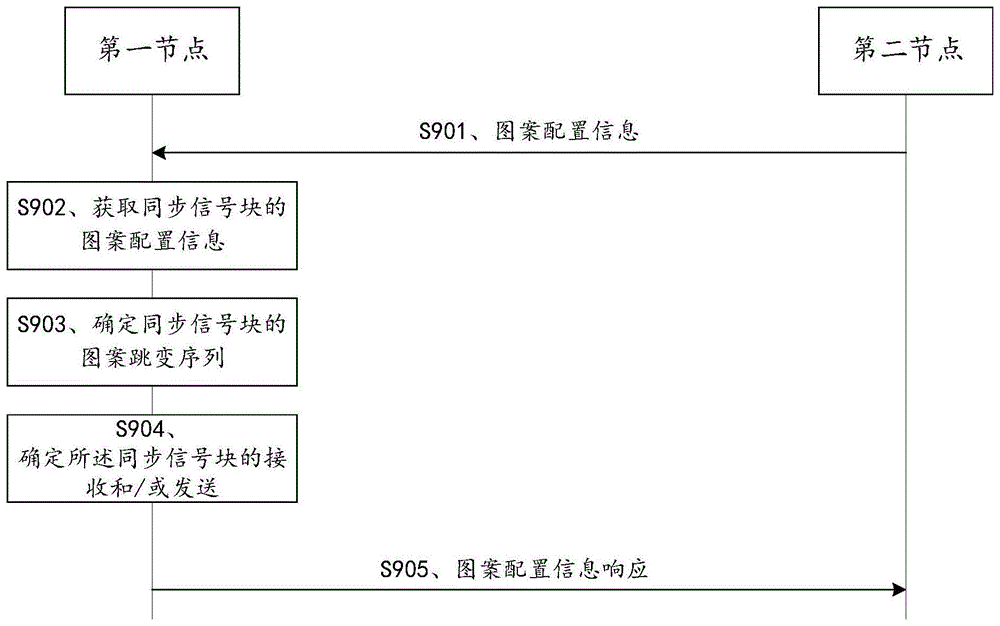
Fig. 9 is a method for configuring a synchronization signal pattern according to an embodiment of the present application. In fig. 9, the first node is an IAB node, and the second node may be a donor or an upper node of the first node. The synchronization signal pattern configuration comprises the steps of:
s901, the second node sends pattern configuration information to the first node.
The pattern configuration information is used to indicate pattern parameters of the synchronization signal block. The pattern parameter includes at least one of pattern period information, node number information, a transmission/reception indication of a synchronization signal block, a start time of an initial pattern period, a repetition factor, an initial pattern of a pattern hopping sequence, a pattern sequence order indication, and sequence period information.
The pattern period information may be the number of SSB sets K within the SSB set group, and may also be an index of the pattern period. In one possible implementation, when the number of supported K is more, the supportable K values can be given in a protocol-defined manner, and an index is assigned to each K value. The first node can determine the value of K according to the index of the pattern period.
The node number information may be a number n configured by the second node for the first node, or may be a number n that the second node indicates the first node to use some other configured or existing identifier, or may be obtained through calculation or derivation according to the existing identifier, where the identifier may be one of a cell Identifier (ID), a Physical Cell Identifier (PCI), a Radio Network Temporary Identifier (RNTI), an MAC address, and an Internet Protocol (IP) address.
In one possible implementation, the numbering of nodes in the IAB system may be reused. For example, under one or more dgnb (donor gnb), when the IAB node is more, the node number n allocated to the IAB node may be reused. To avoid the close IAB nodes from generating the same pattern hopping sequence, the nodes may be clustered (cluster). The numbering of nodes within a cluster does not repeat, while numbering between different clusters may repeat. Optionally, the number of nodes between adjacent clusters is different. Alternatively, the node numbers between adjacent clusters may also be partially the same, but no node numbers are the same at the boundary between two clusters.
The above method of numbering nodes through clusters may result in a reduction of the number of nodes in a cluster, so that a relatively small SSB set, for example, K2 or 3, is adopted, and thus, the value range of the K value may be narrowed in a manner defined by a protocol, and a pattern hopping pattern may be changed into a limited pattern.
Therefore, in the cluster-based scheme, node number information may be configured only for the IAB node. In view of multiplexing of PCI in the wireless access network system, if each IAB node has a different PCI, the PCI may be used as the node number at this time, thereby avoiding the re-allocation of the node number. In this embodiment, the protocol only needs to define one or more of K, a method of generating the pattern hopping sequence, or a transmission/reception indication of the synchronization signal block. The host node only needs to configure the IAB node with the start time of the initial pattern period.
It should be understood that the above-described scheme of clustering nodes can be implemented independently as an embodiment, without depending on the steps of the embodiment shown in fig. 9. Clustering can be implemented as an implementation, and is not required to be embodied in a protocol, but rather, node numbering is arranged based on the physical location of the nodes. The protocol need only be by defining a pattern and a pattern hopping sequence. When K is 2, it is only necessary to define whether the initial pattern of the node is reception or transmission, or to make a determination by parity of the node number. Variations of any of the above described implementations are intended to be within the scope of the present application.
If the above clustering scheme is adopted, the number of nodes that need to be measured mutually is reduced, so that only a limited value of K, such as K2 or K3, can be used. K can be acquired through system information and can also be configured through dedicated signaling, and the dedicated signaling can be RRC signaling, or F1-AP, or F1-AP enhanced protocol. The specific notification method and message format are not limited in this application.
In a possible implementation, it would be an optimized implementation for the second node to configure the node number n for the first node. Due to the configuration of the numbers of the synchronous nodes, the nodes in one area can be configured into node groups which are different from each other and are uniformly distributed, and the pattern hopping sequences of the nodes are not repeated in one sequence period. If the existing node identifiers are used, the nodes possibly in different groups are unevenly distributed, which is not beneficial to shortening the measurement time delay and the overhead.
The transceiving indication of the synchronization signal block is used to indicate the number and/or position of SSB sets received or transmitted in one pattern period. Typically, when only one SSB set is used for reception or transmission, the transceive indication of the synchronization signal block is used to indicate whether K1 or K2 is 1, i.e., whether one reception or one transmission SSB set. Typically, an SSB set is defined for reception in a pattern period defined by the protocol, and the transceiving indication of the synchronization signal block does not need to be sent to the first node. K1 and K2 are as described above and will not be described in detail.
In one possible implementation, the protocol definition has a default value of K, e.g., K is 3 by default, and when K is not configured, K is a default value. In this implementation, the value of K does not necessarily need to be sent to the first node either.
The definition of the repetition factor is as described above. Due to the configuration of the repetition factor, the measurement delay may be increased, but the reliability of the measurement may also be guaranteed. Thus, the configuration of the repetition factor is optional.
The starting time of the initial pattern is used to indicate the time of the first pattern in the pattern hopping sequence, and may be indicated by the frame number and the slot number, or may be determined by the SSB index in the SSB set according to the configuration parameters of the synchronization signal, such as the working frequency point, and may be determined by the frame number and/or the subframe number and the SSB index, and the subframe number may also be the slot number. Other representation methods are also possible, for example, starting with the qth frame after the frame number currently indicated is received, q being an integer. The present application is not limited to the particular pattern starting time representation method.
The initial pattern of the pattern hopping sequence is used to indicate which pattern the pattern hopping sequence starts from. In the default case, when the pattern sequence is automatically determined by the node number n, the initial pattern may not be specified. If the second node specifies the initial pattern, the first node hops from the initial pattern according to the pattern hopping sequence determined in the subsequent step.
The pattern sequence order indication indicates whether the pattern hopping sequence is high-order first or low-order first of respective bits of the node number expressed in L-ary, that is, the pattern hopping sequence is started from the high order of the respective bits of the L-ary expression of the node number, or the pattern hopping sequence is started from the low order. It should be understood that the pattern hopping sequence may also be defined by default starting from the lower or upper bits of the respective bits of the L-ary representation. The pattern sequence order indication does not have to be signaled when the protocol defines.
The sequence period information is period information of the pattern hopping sequence, that is, the number of elements included in the pattern hopping sequence, that is, the number of pattern periods. The length of time for which the sequence is repeated can be controlled by the sequence period information.
In one possible implementation, the pattern configuration information includes an indication that all SSB sets of the first node are in a receive mode. The pattern can be considered to be a special pattern at this time. When all SSB sets of a first node are in receive mode, other nodes cannot discover the presence of the first node. This may be useful in some special cases, for example, when the backhaul link of the first node has a quality problem, the node cannot relay transmission services for other nodes, and the node needs to measure the rest of the nodes as soon as possible. At this time, the transmission of the message may be caused by event triggering, for example, when the first node has a beam failure or a link failure, the node automatically switches to the full reception mode, or when the first node receives a first notification signaling of its upper node, the first node automatically switches to the full reception mode, where the first notification signaling indicates that the upper node has the beam failure or the link failure, or the first notification signaling directly triggers the first node to perform the full reception state.
It should be appreciated that the configuration of the backhaul link SSB set by the first node when all SSB sets are in receive mode may be a stand-alone embodiment, independent of other steps.
In one possible implementation, the second node sends pattern configuration information of other nodes to the first node. For example, where the other node is a neighbor of the first node, the SSB sets sent by the first node's neighbor on the backhaul link may be received by the first node. The first node determines the pattern period that can be measured to other nodes according to the pattern configuration information of other nodes. The pattern configuration information of other nodes may include one or more of the above-mentioned pattern parameters, which are not described in detail.
The pattern period information may further include: the first node transmits and receives the synchronization signal block for a time or number of times to enable mutual measurements between the nodes or groups of nodes. The duration time or the number of times that the first node transmits and receives the synchronization signal block may be configured by the duration time or the number of times that the synchronization signal block lasts, or may be configured by the duration time or the number of times that the pattern period lasts, which is not limited in this application. The time of transmission or duration of the pattern period may be defined by the time or number of times the first node transmits and receives the synchronization signal block.
S902, the first node acquires pattern information of the synchronous signal block.
The first node acquiring the pattern configuration information of the synchronization signal block may acquire the pattern configuration information through S901, so that the pattern may be determined according to the pattern configuration information. The pattern may be any one of the patterns in the pattern period. The pattern determined by the first node is mainly the reception or transmission pattern of the SSB sets in the pattern period.
The first node may also acquire pattern configuration information of the synchronization signal block through a pre-configured parameter. If all the pattern parameters in step S901 are protocol defined or preconfigured, the first node does not need the second node to explicitly configure the pattern configuration information of the first node through signaling. For example, the node number uses PCI, K uses the protocol defined default value of 3, and a SSB set is configured for reception within a default pattern period. After the first node finishes starting, or starts to transmit the SSB of the access link, the first node starts to receive or transmit the SSB of the backhaul link. At this time, the first node can obtain the pattern only by obtaining the pre-configured pattern parameters.
It should be appreciated that the use of all default pattern parameters may not result in a more optimal configuration, and thus, the pattern parameters defined by the preconfiguration or protocol described above are only one extreme case. Basic parameters, such as node number information, start time of initial pattern period, etc., are generally required to be configured.
In one possible implementation, the sending of SSB sets configures the DU functions sent by the donor superordinate node to the IAB node, while the receiving of SSB sets configures the MT functions sent by the donor superordinate node to the IAB node. And the IAB node implicitly determines the SSB set transceiving pattern according to the transmission and reception configuration. Further, the transceiving pattern may be implemented by a protocol definition or SSB set transmission and reception priority configured by the upper node.
The transmission or reception of SB set may be semi-persistent, periodic, or dynamic. After the semi-persistent inclusion of SSB set configuration, the transmission and/or reception procedures of SSB sets are enabled by procedures (signaling) of activation and/or deactivation.
In a possible implementation, the donor superordinate node configures a periodic SSB set for the DU of the IAB node, and may also configure the number K of SSB sets in the set. Since the SSB sets are periodic, the periodic SSB sets are divided into K groups, with a pattern period formed between each K SSB sets. At this time, the pattern period (or the period of the SSB set groups) is K times the SSB set period, and K SSB sets of one SSB set group are K periods of the SSB sets, as shown in FIG. 7.
In one possible implementation, the donor superordinate node configures a number of periodic or semi-persistent SSB sets for the DUs of the IAB node, as shown in fig. 8. Taking IAB node0 as an example, three periodic SSB sets are configured, and as shown in the figure, SSB set 801, SSB set 802, and SSB set 803 are 3 periodic SSB sets respectively. Wherein, SSB set 801 and SSB set 804 are configured for the same SSB set, and the period is the interval between SSB set 801 and SSB set 804; SSB set 802 and SSB set 805 are configured for the same SSB set, and the period is the interval between SSB set 802 and SSB set 805; SSB set 803 and SSB set 806 are configured for the same SSB set, and the period is the interval between SSB set 803 and SSB set 806. The IAB node1 and IAB node 2 are the same and will not be described again.
In the configuration shown in FIG. 8, the SSB set group or pattern period has no fixed relationship to the period of consecutive SSB sets. Consecutive SSB sets comprise two SSB sets that are adjacent in the time domain, possibly from different configurations of SSB sets. At this point, the SSBs in the SSB set come from different periodic SSB set configurations. It is understood that the periods of different SSB sets may be the same, may be different, and may not overlap each other in the time domain.
In the above embodiment, the number of K is the same as the number of SSB sets. As shown in FIG. 8, the period of each SSB set is the same, the period (pattern period) of the SSB set groups is the same as the period of the SSB sets, and the SSB sets in one SSB set group are respectively from different configurations of SSB sets. The configuration mode can be well adapted to the current SSB set configuration mode, and only the existing configuration mode needs to be expanded.
The present application does not limit the specific form of the SSB set transmission configuration of the DU. The configuration of the IAB DU by the upper node is typically performed via the F1-AP interface or the F1-AP enhanced interface, but not exclusively via RRC signaling.
Likewise, the donor or superordinate node may also configure the reception of SSB sets for the MT of the IAB node. Similarly, the reception mode of the SSB sets in the pattern information (SSB set group) may be performed by one set of SSB set configuration or multiple sets of SSB set configuration. The specific method is similar to the method of fig. 7 or 8, only the receiving or transmitting mode of the SSB set is different, and is not described again.
In one possible implementation, the donor or superordinate node configures the reception pattern directly for the IAB node. In another possible implementation, the donor or superordinate node configures the MT with periodic SSB set reception, where the reception period of the SSB sets equals the period of the SSB set, i.e. the period of the SSB set pattern. And reception of the SSB set may perform shift (offset) hopping, thereby enabling hopping of the pattern. Alternatively, the superordinate node may inform the IAB node of the measurable or target measuring nodes within different patterns or different SSB set reception periods.
Taking fig. 6 as an example, the sequence of the transmit-receive patterns adopted by the IAB node is { P0, P1, P2}, the corresponding SSB set receiving period is the period of the SSB set group, and different transmit-receive patterns can be obtained by adopting different measurement shifts in different receiving periods. Therefore, the hopping sequence of the SSB set pattern can now be embodied by the hopping of the shift values of the measurement configuration. Since the SSB set reception period is the period of the SSB set group, the period of the SSB set group may not need to be explicitly configured in this case. In general, the upper node configures the IAB DU through RRC signaling, but does not exclude the case of F1-AP.
In another possible implementation, the superordinate node configures the reception of multiple sets of SSB sets for the IAB node, for example, M sets (where M is the length of the pattern hopping sequence), and the reception configurations of different SSB sets may have different periodicity and/or shift values. As an example, the period of each set of SSB set reception is M times the pattern period, and different SSB set reception adopts different configurations, thereby implementing the above-described SSB set transceiving pattern and hopping of the transceiving pattern. Optionally, the superordinate node may inform the IAB node of the measurable or target measured node under different SSB set reception configurations.
The SSB set should be sent and received with a priority, which may be defined by the protocol, or may be configured by the donor or superior node. After SSB set transmission and SSB set reception of the IAB node are configured respectively, the IAB node can obtain a transceiving pattern of the SSB set and hopping of the transceiving pattern according to the priority of the SSB set transmission and reception.
It should be noted that the above examples do not exclude both cases where the IAB node is only configured with transmission or reception of SSB sets.
In one possible implementation, the IAB node receives in all SSB set positions, i.e., in a fully received state. The IAB node may enter the full reception state in various ways, such as signaling trigger of the upper node, or automatic trigger after the state of the IAB node changes, for example, the IAB node automatically enters the full reception state after a link failure or a beam failure. In the full reception state, the SSB set reception behavior of the IAB node is different from that in the normal case. Illustratively, the full reception state can be achieved in three ways: 1) SSB set reception period shrinking; 2) the reception period of SSB sets is unchanged, but the IAB node measures on all shifts within the period. 3) Activate an additional set of SSB set reception configurations that are dedicated to full reception and normally inactive. According to the above three ways, in some special cases, there may not be any SSB set transmitted by the receiving position of the partial SSB sets, and at this time, the IAB node cannot detect any SSB set of the node, thereby causing waste of resources. Thus, the following constraints can be added: in one possible implementation, the IAB node may not receive SSB sets when the reception of SSB sets does not coincide with the transmission time domain of any SSB set. The SSB set transmission position may be an SSB set transmission position of the IAB node itself, or an SSB set transmission position of the other node notified by the upper node to the IAB node.
S903, the first node determines a pattern hopping sequence of the synchronization signal block.
The first node determining the pattern hopping sequence of the synchronization signal block comprises: the first node receives the information of the pattern hopping sequence sent by the second node; or the first node determines the pattern hopping sequence according to the node number information, the pattern period information and the sequence period information. The information of the pattern hopping sequence includes one or more of an initial pattern of the pattern hopping sequence, a pattern sequence order indication, sequence period information, and a pattern hopping sequence index, for assisting in determining the pattern hopping sequence.
In a possible implementation, the information of the pattern hopping sequence may also be a pattern sequence configured by the second node or an index of the pattern sequence. Specifically, a limited number of pattern hopping sequences can be defined by a protocol and numbered (indexed), and the pattern hopping sequences can be uniquely determined by the pattern hopping sequence index. For example, different K values and pattern hopping sequences corresponding to M values can be defined, and an index can be assigned to different sequences. The second node indicates the pattern sequence used by the first node by means of a pattern hopping sequence index.
Specifically, the first node may obtain the pattern hopping sequence according to the method for determining the pattern hopping sequence in the foregoing embodiment. For example, when the number of patterns in one pattern period is L equal to 3, if the sequence period M is 2, the pattern hopping sequence can be obtained by performing f-floor function and mod function operations on the node numbers. Or expressing the node number by a ternary system according to the node number, and determining to take two patterns from the lower order of the ternary system as sequence elements according to the sequence period information and the pattern sequence indication. The specific determination mode depends on the configuration of the parameters, and the application is not limited.
In addition, if the second node designates the initial pattern of the pattern hopping sequence, the first element of the pattern hopping sequence determined by the first node starts from the designated initial pattern, and then the pattern hopping sequence can be obtained by sequentially taking M elements according to the pattern sequence generated by the pattern hopping sequence determined by the mathematical method. For example, the pattern order generated by the pattern hopping sequence is determined to be (P0, P1, P2) by the above mathematical method, and if the specified initial pattern is P2 and M is 2, the pattern hopping sequence is obtained to be (P2, P0).
When the second node does not specify the initial pattern of the pattern hopping sequence, or the protocol definition starts from the lower or upper bits of the L-ary representation of the node number, it is only necessary to start from the lower or upper bits of the L-ary representation of the node number according to the sequence period.
In one possible implementation, the second node informs the first node of the pattern hopping sequences of a plurality of third nodes. And the third node is the rest IAB nodes or the rest network equipment. The specific notification method includes that the second node notifies the corresponding relationship between the identifier of the third node and the pattern hopping sequence, wherein the representation of the third node may be identification information such as PCI, and the identifier of the third node is not limited in the present application. The pattern hopping sequence notification is the same as the scheme, and is not described again.
S904, the first node determines reception and/or transmission of the synchronization signal block.
The first node obtains the pattern hopping sequence and, after the start time of the initial pattern period, can begin receiving or transmitting SSB sets over the backhaul link. According to the pattern in the pattern hopping sequence, in one pattern period, the time domain information of the received or transmitted SSB set is determined according to the corresponding pattern.
For example, for K3, in the first pattern period, the node uses pattern P0, pattern P0 indicates that the 0 th SSB set is received and the 1 st and 2 nd SSB sets are transmitted, and then the first node measures the SSB sets of other nodes at the position of the 0 th SSB set.
S905, the first node sends a pattern configuration information response to the second node.
And informing the second node of receiving the pattern configuration information through the pattern configuration information response.
Through the above embodiments, the first node may obtain the receiving or transmitting mode of the SSB set in one pattern period on the backhaul link, and through pattern hopping, the nodes in the same group may measure each other after the pattern hopping. The method can reduce the time delay of mutual measurement among the nodes, and solves the problems of overlong time for completing mutual measurement and complex system configuration when the number of IAB nodes in the system is large.
Fig. 10 is a schematic diagram of updating pattern configuration information according to an embodiment of the present application. In an IAB system, inter-IAB node measurements may be optimized, possibly due to an increase or decrease in IAB nodes. Accordingly, the pattern configuration information of the node can be updated. The method specifically comprises the following steps:
S1001-S1005 are the same as S901-S905, and are not described again.
S1006, the second node sends a pattern reconfiguration instruction to the first node.
The pattern reconfiguration indication is used to instruct the first node to reconfigure the pattern configuration information. By reconfiguring the pattern configuration information, the first node may be caused to update the pattern and/or the pattern hopping sequence.
Specifically, the pattern reconfiguration indication may include one or more parameters of the pattern parameters in the aforementioned pattern configuration information, and the specific parameters are not described again.
It will be appreciated that when the second node reconfigures the pattern configuration information of the first node, it is possible that many parameters do not need to be reconfigured, but only some updated parameters need to be configured, e.g. the node number information does not need to be reconfigured, the pattern period information K may not need to be reconfigured either, but the sequence period information needs to be reconfigured. Of course, the pattern period information K may also be reconfigured, e.g., when IAB nodes in the system suddenly increase or decrease, which may result in K needing to be reconfigured.
The pattern reconfiguration indication may further include: a start time of the updated pattern hopping sequence and/or pattern configuration information. If a new start time is not specified, the protocol may define that transmission or reception of a synchronization signal for a new pattern hopping sequence and/or pattern starts q frames or subframes or slots after the pattern reconfiguration indication is received, q may be a value specified by the protocol, and is typically an integer. The start time of the pattern hopping sequence and/or the pattern configuration information is the start time of the new initial pattern period, and the start time of the initial pattern period is as described above and is not described again.
When the pattern configuration information is reconfigured, the first node needs to determine a new pattern hopping sequence and/or pattern according to the new pattern configuration information and start a new SSB set reception or transmission mode at a specified start time according to the start time of the initial pattern period.
And S1007, the first node sends a pattern reconfiguration indication response to the second node.
And after receiving the pattern reconfiguration instruction, the first node sends a pattern reconfiguration instruction response to the second node.
By the embodiment, the problem that patterns and/or pattern hopping sequences measured by nodes are possibly not optimal after the IAB nodes in the IAB system are changed is solved. By the scheme, when the IAB node in the IAB system changes, the receiving and/or sending mode of the synchronous signal on the return link is optimized, and the measurement time delay and the resource consumption are reduced.
In the embodiments described above in fig. 9 or fig. 10, the pattern configuration information response, the pattern reconfiguration indication, and the pattern reconfiguration indication response may be transmitted via RRC or an enhanced version of the F1-AP protocol or the F1-AP protocol. The specific signaling interface depends on the protocol definition, and the application is not restricted.
The above-mentioned scheme provided by the embodiment of the present application is introduced mainly from the perspective of interaction between network elements. It will be appreciated that the respective network elements, e.g. the first node and the second node, for performing the above-described functions, comprise corresponding hardware structures and/or software modules for performing the respective functions. Those of skill in the art would readily appreciate that the present application is capable of being implemented as hardware or a combination of hardware and computer software for performing the exemplary network elements and algorithm steps described in connection with the embodiments disclosed herein. Whether a function is performed as hardware or computer software drives hardware depends upon the particular application and design constraints imposed on the solution. Skilled artisans may implement the described functionality in varying ways for each particular application, but such implementation decisions should not be interpreted as causing a departure from the scope of the present application.
In the embodiment of the present application, functional modules may be divided into the first node and the second node according to the above method examples, for example, the first node and the second node may be divided into the functional modules, or two or more functions may be integrated into one processing module. The integrated module can be realized in a hardware mode, and can also be realized in a software functional module mode. It should be noted that, in the embodiment of the present application, the division of the module is schematic, and is only one logic function division, and there may be another division manner in actual implementation. It should be understood that the second node may be an IAB node or a donor base station.
Fig. 11 is a schematic diagram of a possible structure of an IAB node according to the above embodiments provided in the present application. In this application, the first node is an IAB node. The first node includes: receiving section 1101, acquiring section 1102, and transmitting section 1103. A receiving unit 1101, configured to support a first node to perform S901 in fig. 9, or S1001 and S1006 in fig. 10, and to support a function of the first node in the foregoing embodiment to receive a pattern reconfiguration indication sent by a second node to perform reconfiguration of a pattern and a pattern hopping sequence, and to support a function of receiving SSB sets sent by other IAB nodes to implement measurement and node discovery, a function of receiving information of the pattern hopping sequence sent by the second node, and a function of supporting reception of pattern configuration information of other nodes sent by the second node; an obtaining unit 1102, configured to support a first node to perform S902 in fig. 9 or S1002 in fig. 10; a processing unit 1103, configured to support the first node to perform S903 and S904 in fig. 9 or S1003 and S1004 in fig. 10, and to support the first node in the foregoing embodiment to process the received message or signaling.
The first node further comprises: a sending unit 1104, configured to support the first node to execute S905 in fig. 9, or S1005 and S1007 in fig. 10, and configured to support the first node to send the synchronization signal block on the backhaul link after receiving and/or sending the synchronization signal block in the foregoing embodiment.
In terms of hardware implementation, the sending unit 1101 may be a sender, the receiving unit 1103 may be a receiver, and the receiver and the sender are integrated in a communication unit to form a communication interface.
Fig. 12 is a schematic diagram of a possible logical structure of the first node involved in the foregoing embodiments provided in the present application. The first node includes: a processor 1202. In the embodiment of the present application, the processor 1202 is configured to control and manage the action of the first node, for example, the processor 1202 is configured to support the first node to perform S903 and S904 in fig. 9, S1003 and S1004 in fig. 10 in the foregoing embodiment, and to support the first node in the foregoing embodiment to process the received message or signaling; the processor 1202 may also be configured to support S902 in fig. 9 and S1002 in fig. 10 performed by the first node in the foregoing embodiment to acquire pattern configuration information of the synchronization signal block. Optionally, the first node may further include: a memory 1201 and a communication interface 1203; the processor 1202, the communication interface 1203, and the memory 1201 may be connected to each other or to each other through a bus 1204. The communication interface 1203 is configured to support communication with the first node, and the memory 1201 is configured to store program codes and data of the first node. The processor 1202 calls the code stored in the memory 1201 for control management. The memory 1501 may or may not be coupled to the processor.
The processor 1202 may be, among other things, a central processing unit, a general purpose processor, a digital signal processor, an application specific integrated circuit, a field programmable gate array or other programmable logic device, transistor logic, a hardware component, or any combination thereof. Which may implement or perform the various illustrative logical blocks, modules, and circuits described in connection with the disclosure. The processor may also be a combination of computing functions, e.g., comprising one or more microprocessors, a digital signal processor and a microprocessor, or the like. The bus 1204 may be a Peripheral Component Interconnect (PCI) bus, an Extended Industry Standard Architecture (EISA) bus, or the like. The bus may be divided into an address bus, a data bus, a control bus, etc. For ease of illustration, only one thick line is shown in FIG. 12, but this is not intended to represent only one bus or type of bus.
The processor 1202, the communication interface 1203 and the memory 1201 may be integrated into one integrated circuit to perform the actions or functions performed by all the first nodes in the foregoing embodiments.
Fig. 13 is a schematic diagram of a possible structure of the second node according to the above embodiment of the present application. In this application, the second node is a relay node. The second node includes: a transmitting unit 1301 and a receiving unit 1303. The sending unit 1301 is configured to support the second node to perform S901 in fig. 9, S1001 in fig. 10, and S1006, and to support the second node to send the pattern reconfiguration instruction to the first node and send the pattern configuration information of other nodes to the first node in the foregoing embodiment; the receiving unit 1303 is configured to support the second node to execute S905 in fig. 9 or S1005 and S1007 in fig. 10. The second node further comprises: a processing unit 1302, the processing unit 1302, is configured to support the second node to perform the processing on the received message in fig. 9, or determine a parameter for the sent message, such as a relevant parameter in the pattern configuration information.
In terms of hardware implementation, the sending unit 1301 may be a sender, the receiving unit 1303 may be a sender, and a receiver and the sender are integrated in a communication unit to form a communication interface.
Fig. 14 is a schematic diagram of a possible logical structure of the second node according to the foregoing embodiments provided in this application. The second node includes: a processor 1402. In the embodiment of the present application, the processor 1402 is configured to control and manage the actions of the second node, for example, the processor 1402 is configured to support the second node to perform the processing of various receiving or sending messages in fig. 9 in the foregoing embodiment, and prepare relevant parameters of relevant pattern configuration information for the first node. Optionally, the second node may further include: a memory 1401 and a communication interface 1403; the processor 1402, the communication interface 1403, and the memory 1401 may be connected to each other or to each other through a bus 1404. Wherein the communication interface 1403 is used for supporting communication of the second node and the memory 1401 is used for storing program codes and data of the second node. The processor 1402 calls the code stored in the memory 1401 for control management. The memory 1701 may or may not be coupled to the processor.
Processor 1402 may be, among other things, a central processing unit, a general purpose processor, a digital signal processor, an application specific integrated circuit, a field programmable gate array or other programmable logic device, transistor logic, a hardware component, or any combination thereof. Which may implement or perform the various illustrative logical blocks, modules, and circuits described in connection with the disclosure. The processor may also be a combination of computing functions, e.g., comprising one or more microprocessors, a digital signal processor and a microprocessor, or the like. The bus 1704 may be a Peripheral Component Interconnect (PCI) bus, an Extended Industry Standard Architecture (EISA) bus, or the like. The bus may be divided into an address bus, a data bus, a control bus, etc. For ease of illustration, only one thick line is shown in FIG. 14, but this is not intended to represent only one bus or type of bus.
The processor 1402, the communication interface 1403 and the memory 1401 described above may also be integrated in one integrated circuit, performing the actions or functions performed by all the second nodes in the previous embodiments.
In another embodiment of the present application, a readable storage medium is further provided, where a computer executing instruction is stored in the readable storage medium, and when a device (which may be a single chip, a chip, or the like) or a processor executes fig. 9 and 10 and reconfigures the pattern configuration information of the first node, the computer executing instruction in the storage medium is read. The aforementioned readable storage medium may include: u disk, removable hard disk, read only memory, random access memory, magnetic or optical disk, etc. for storing program codes.
In another embodiment of the present application, there is also provided a computer program product comprising computer executable instructions stored in a computer readable storage medium; the computer executable instructions may be read by at least one processor of the apparatus from a computer readable storage medium, and execution of the computer executable instructions by the at least one processor causes the apparatus to implement the steps of the first node and the second node in the synchronization signal transmission and reception methods provided in fig. 9 and 10.
In another embodiment of the present application, a communication system is also provided, which includes at least a first node and a second node. Wherein, the first node may be the first node provided in fig. 11 or fig. 12, and is configured to execute the steps of the first node in the method for sending and receiving the synchronization signal provided in fig. 9 and fig. 10; and/or the second node may be the second node provided in fig. 13 or fig. 14, and is configured to perform the steps performed by the second node in the methods for transmitting and receiving the synchronization signal provided in fig. 9 and fig. 10. It should be understood that the communication system may include a plurality of first nodes and second nodes, or a plurality of first nodes and a second node, the second node configuring the pattern configuration information for the plurality of first nodes, so that the plurality of first nodes in the system can be mutually measured and discovered, and the measurement delay and the resource overhead are minimized.
In the embodiment of the present application, by configuring the pattern configuration information of the first node, the nodes in the system obtain the pattern hopping sequence, and implement receiving or sending of the SSB set according to the obtained pattern hopping sequence and the pattern in the sequence, the time delay of mutual discovery between the nodes in the IAB system is reduced, the overhead is reduced, and the configuration of the system is simplified.
Finally, it should be noted that: the above description is only an embodiment of the present application, but the scope of the present application is not limited thereto, and any changes or substitutions within the technical scope of the present disclosure should be covered by the scope of the present application. Therefore, the protection scope of the present application shall be subject to the protection scope of the claims.