CN111448024B - Cutting device for cutting corrugated tubing and guide projection in a cutting device - Google Patents
Cutting device for cutting corrugated tubing and guide projection in a cutting device Download PDFInfo
- Publication number
- CN111448024B CN111448024B CN201880079266.6A CN201880079266A CN111448024B CN 111448024 B CN111448024 B CN 111448024B CN 201880079266 A CN201880079266 A CN 201880079266A CN 111448024 B CN111448024 B CN 111448024B
- Authority
- CN
- China
- Prior art keywords
- cutting
- opening
- guide
- cutting device
- edge
- Prior art date
- Legal status (The legal status is an assumption and is not a legal conclusion. Google has not performed a legal analysis and makes no representation as to the accuracy of the status listed.)
- Active
Links
Images


Classifications
-
- B—PERFORMING OPERATIONS; TRANSPORTING
- B26—HAND CUTTING TOOLS; CUTTING; SEVERING
- B26D—CUTTING; DETAILS COMMON TO MACHINES FOR PERFORATING, PUNCHING, CUTTING-OUT, STAMPING-OUT OR SEVERING
- B26D3/00—Cutting work characterised by the nature of the cut made; Apparatus therefor
- B26D3/16—Cutting rods or tubes transversely
- B26D3/169—Hand held tube cutters
-
- H—ELECTRICITY
- H02—GENERATION; CONVERSION OR DISTRIBUTION OF ELECTRIC POWER
- H02G—INSTALLATION OF ELECTRIC CABLES OR LINES, OR OF COMBINED OPTICAL AND ELECTRIC CABLES OR LINES
- H02G1/00—Methods or apparatus specially adapted for installing, maintaining, repairing or dismantling electric cables or lines
- H02G1/12—Methods or apparatus specially adapted for installing, maintaining, repairing or dismantling electric cables or lines for removing insulation or armouring from cables, e.g. from the end thereof
- H02G1/1202—Methods or apparatus specially adapted for installing, maintaining, repairing or dismantling electric cables or lines for removing insulation or armouring from cables, e.g. from the end thereof by cutting and withdrawing insulation
- H02G1/1204—Hand-held tools
- H02G1/1221—Hand-held tools the cutting element rotating about the wire or cable
- H02G1/1224—Hand-held tools the cutting element rotating about the wire or cable making a transverse cut
-
- H—ELECTRICITY
- H02—GENERATION; CONVERSION OR DISTRIBUTION OF ELECTRIC POWER
- H02G—INSTALLATION OF ELECTRIC CABLES OR LINES, OR OF COMBINED OPTICAL AND ELECTRIC CABLES OR LINES
- H02G3/00—Installations of electric cables or lines or protective tubing therefor in or on buildings, equivalent structures or vehicles
- H02G3/02—Details
- H02G3/04—Protective tubing or conduits, e.g. cable ladders or cable troughs
- H02G3/0462—Tubings, i.e. having a closed section
- H02G3/0468—Corrugated
Landscapes
- Engineering & Computer Science (AREA)
- Architecture (AREA)
- Civil Engineering (AREA)
- Structural Engineering (AREA)
- Life Sciences & Earth Sciences (AREA)
- Forests & Forestry (AREA)
- Mechanical Engineering (AREA)
- Knives (AREA)
- Harvester Elements (AREA)
Abstract
本发明涉及一种用于切割波纹管(2)的切割设备(1),所述切割设备具有切割开口(9),所述切割开口由两个开口部段构成,其中,两个开口部段分别具有刀刃(24、25)以及分别具有垂直于所述刀刃(24、25)相间隔的且与刀刃(24、25)相同指向地延伸的导引凸出部(20‑23)。为了在使用方面进一步改进这种类型的切割设备,在此建议,所述刀刃(24、25)连同导引凸出部(20‑23)分别沿纵向构造在具有罩壳纵轴线的罩壳件(3、4)的端侧,每个罩壳件(3、4)的第一和第二纵向边缘(5‑8)垂直于刀刃(24、25)的定向延伸,并且所述切割开口(9)在闭合状态下参照切割开口(9)的穿过第一和第二纵向边缘(5‑8)延伸的中平面(M)在所述中平面(M)的延伸方向上具有最大的开口尺寸(d),并且所述罩壳件(3、4)沿纵向的延伸尺寸(a)等于最大的开口尺寸(d)的1.2倍至10倍。此外,本发明还涉及一种导引凸出部(20‑23),在用于切割波纹管(2)的切割设备(1)的切割开口(9)中在切割开口(9)的闭合状态下所述导引凸出部彼此相对置并且相同指向地延伸。
The invention relates to a cutting device (1) for cutting corrugated pipes (2), which has a cutting opening (9), which is formed by two opening sections, wherein the two opening sections Each has a knife edge (24, 25) and a guide protrusion (20-23) which is spaced perpendicularly to the knife edge (24, 25) and extends in the same direction as the knife edge (24, 25). In order to further improve a cutting device of this type in terms of use, it is proposed here that the cutting edges (24, 25) together with the guide projections (20-23) are each longitudinally formed on the housing part with the longitudinal axis of the housing (3, 4), the first and second longitudinal edges (5‑8) of each casing part (3, 4) extend perpendicular to the orientation of the cutting edge (24, 25), and the cutting opening ( 9) the midplane (M) extending through the first and second longitudinal edges (5-8) in the closed state with reference to the cutting opening (9) has the largest opening in the direction of extension of said midplane (M) dimension (d), and the longitudinal extension dimension (a) of the casing parts (3, 4) is equal to 1.2 to 10 times the largest opening dimension (d). Furthermore, the invention relates to a guide lug (20‑23) in the closed state of the cutting opening (9) of a cutting device (1) for cutting corrugated tubes (2) The guide lugs described below face each other and extend in the same direction.
Description
技术领域technical field
本发明首先涉及一种用于切割波纹管的切割设备,所述切割设备具有切割开口,所述切割开口由两个开口部段构成,其中,两个开口部段分别具有刀刃以及分别具有垂直于所述刀刃相间隔的且与刀刃相同指向地延伸的导引凸出部。The invention firstly relates to a cutting device for cutting bellows, which has a cutting opening which is formed by two opening sections, wherein the two opening sections each have a cutting edge and each have a cutting edge perpendicular to the The guide protrusions which are spaced apart from the blade and extend in the same direction as the blade.
此外,本发明还涉及一种导引凸出部,在用于切割波纹管的切割设备的切割开口中在切割开口的闭合状态下所述导引凸出部彼此相对置并且相同指向地延伸,在所述切割开口的闭合状态下所述导引凸出部确定切割开口的开口轮廓,其中,沿着在闭合状态下穿过切割开口的中平面观察,相互对置的导引凸出部具有凹形延伸的自由的边缘。Furthermore, the invention relates to a guide lug which extends opposite one another and in the same direction in a cutting opening of a cutting device for cutting corrugated tubes in the closed state of the cutting opening, In the closed state of the cutting opening, the guide lugs determine the opening contour of the cutting opening, wherein, viewed along a mid-plane passing through the cutting opening in the closed state, mutually opposite guide lugs have Free edge of concave extension.
尤其由塑料材料制成的波纹管优选在电线或者类似物的布设中应用。电线布置在波纹管中并且以此防止受脏污和机械损伤。Corrugated pipes, in particular made of plastic material, are preferably used in the routing of electrical lines or the like. The wires are arranged in corrugated tubes and are thus protected from dirt and mechanical damage.
背景技术Background technique
已知使用相应设计的切割设备切割这种波纹管。对此例如参考文献DE297 11 774U1。该实用新型公开了一种用于切割波纹管的切割设备,该切割装置是钳子形状设计的,具有两个可围绕枢转轴线枢转的开口部段,在开口部段中分别布置有刀刃和导引凸出部,还具有两个持握臂,从开口部段观察,持握臂在枢转轴线的另一侧延伸。导引凸出部设计并且布置用于嵌入待切割的波纹管的波谷中,刀刃与导引凸出部相邻地布置,以便在波纹管的波峰区域中进行切割。对于现有技术还参照文献CH 682471 A5。由此已知的波纹管切割器设计带有用于刀刃的螺旋弹簧式的固持部和导引凸出部。It is known to cut such bellows with correspondingly designed cutting devices. For this, reference is made, for example, to DE 297 11 774 U1. The utility model discloses a cutting device for cutting corrugated pipes. The cutting device is designed in the shape of pliers and has two opening sections that can pivot around a pivot axis, and a blade and a cutting edge are respectively arranged in the opening sections. The guide lug also has two gripping arms which extend on the other side of the pivot axis viewed from the opening section. The guide lug is designed and arranged to engage in a valley of the corrugated tube to be cut, and the knife edge is arranged adjacent to the guide lug in order to cut in the region of the crest of the corrugated tube. Reference is also made to document CH 682471 A5 for the prior art. The bellows cutter known thus is designed with a helical spring-like holder and guide projection for the cutting edge.
此外由文献EP 12955688 A2和文献DE 2159744 A1已知用于切割管件的装置,其分别仅具有向内突出的刀刃并且是钳子状设计的,带有围绕枢转轴线能枢转的开口部段。由文献DE 202014105596 U1和US 6725533 B1已知一种剥线工具,其用于去除电缆绝缘层。Furthermore, devices for cutting pipes are known from EP 12955688 A2 and DE 2159744 A1, which each have only inwardly protruding blades and are designed in the form of pliers with an opening section pivotable about a pivot axis. A stripping tool is known from documents DE 202014105596 U1 and US 6725533 B1, which are used for removing cable insulation.
发明内容Contents of the invention
从现有技术出发,本发明要解决的技术问题是在操作方面有利地设计用于切割波纹管的切割设备。Starting from the prior art, the technical problem to be solved by the present invention is to design a cutting device for cutting corrugated tubes in an operationally advantageous manner.
所述技术问题根据本发明首先通过权利要求1的技术方案的解决,其中规定,所述刀刃连同导引凸出部分别沿纵向构造在具有罩壳纵轴线的罩壳件的端侧,每个罩壳件的第一和第二纵向边缘垂直于刀刃的定向延伸,并且所述切割开口在闭合状态下参照切割开口的穿过第一和第二纵向边缘延伸的中平面在所述中平面的延伸方向上具有最大的开口尺寸,并且所述罩壳件沿纵向的延伸尺寸等于最大的开口尺寸的1.2倍至10倍,并且所述刀刃的切割边缘向内朝切割开口的方向被所述导引凸出部的边缘超出。The technical problem is firstly solved according to the invention by the technical solution of
基于该设计方案给出一种有利于使用地设计的、使用价值更高的切割设备。基本上构成切割设备的罩壳件可以不丢失地在区域中相互连接。切割设备的使用位置优选是罩壳件的闭合位置或者从打开位置出发向闭合位置的方向到达的位置,其中,使用区域相当于具有刀刃以及导引凸出部的区域,使用区域可以布置在总体上在使用位置上伸长的管状的切割设备的端侧。Based on this design scheme, a cutting device with a favorable design and higher use value is proposed. The housing parts that essentially form the cutting device can be connected to one another in the region without loss. The use position of the cutting device is preferably the closed position of the housing part or the position arriving in the direction of the closed position from the open position, wherein the use area corresponds to the area with the blade and the guide projection, and the use area can be arranged in the overall On the end side of the elongated tubular cutting device in the position of use.
切割设备在人体工学上有利地设计,尤其是在切割波纹管期间有利地将力导入切割设备方面。由于罩壳件通过大拇指和至少一个手指优选所有手指必要时完全抓握,切割设备可以基本上在切割波纹管壁的情况下从手腕向开始围绕波纹管纵轴线转动。在此并不强制需要切割设备围绕波纹管纵轴线转动完整的360°或者更多。由于优选有多个刀刃,尤其在每个罩壳件上分别布置刀刃,切割设备围绕波纹管纵轴线以例如直至180°的转动就足够了,此外例如从基础位置开始分别以约90°沿相反的转动方向的转动。The cutting device is ergonomically advantageous, especially with regard to the advantageous introduction of forces into the cutting device during cutting of the bellows. Since the housing part is gripped completely by the thumb and at least one finger, preferably all fingers, the cutting device can be rotated around the longitudinal axis of the bellows substantially starting from the wrist while cutting the wall of the bellows. It is not mandatory here that the cutting device be turned by a complete 360° or more about the longitudinal axis of the bellows. Since there are preferably a plurality of cutting edges, in particular a respective arrangement of the cutting edges on each housing part, it is sufficient to rotate the cutting device around the longitudinal axis of the bellows, for example up to 180°, in addition, for example starting from the base position at approximately 90° in opposite directions. rotation in the direction of rotation.
在优选的设计方案中,通过选择最大的开口尺寸和罩壳件的在使用位置中沿波纹管纵轴线的延伸观察的延伸尺寸,可以实现在人体工学上有利的将切割设备基本上整体握在手心里。在此优选的是仅罩壳件构成抓握。In a preferred refinement, by selecting the largest opening size and the extension of the housing part viewed along the extension of the longitudinal axis of the bellows in the position of use, an ergonomically advantageous holding of the cutting device substantially as a whole can be achieved. palm. It is preferred here that only the housing part forms the grip.
关于在切割开口中延伸的导引凸出部方面,所述技术问题按照本发明的另外的发明构思通过一种导引凸出部解决,在此规定,相互对置的导引凸出部的边缘不同地弯曲延伸,其中,一个弯曲的边缘在最大曲率的区域中的半径比另一个弯曲的边缘的半径大1.2倍至10倍。With regard to the guide lugs extending in the cutting opening, the technical problem is solved according to a further inventive concept of the present invention by a guide lug, in which it is provided that the mutually opposite guide lugs The edges run in different curves, wherein the radius of one curved edge in the region of maximum curvature is 1.2 to 10 times greater than the radius of the other curved edge.
导引凸出部的这种设计方案也可以实现有利的使用,此外实现结合不同直径的波纹管的有利的使用。相互对置的导引凸出部在使用位置中优选嵌入波纹管的同一波谷中,通过其不一样弯曲的边缘构成切割设备也在不同直径的波纹管的情况中有利的导引贴靠。根据波纹管直径,切割设备的切割开口产生不同的扩张以及两个导引凸出部的相应不同的定向和定位。Such an embodiment of the guide lugs also enables an advantageous use, moreover an advantageous use in combination with bellows of different diameters. In the position of use, the mutually opposite guide lugs preferably engage in the same trough of the corrugated tube, with their differently curved edges forming an advantageous guiding abutment of the cutting device also in the case of corrugated tubes of different diameters. Depending on the bellows diameter, a different expansion of the cutting opening of the cutting device and a corresponding different orientation and positioning of the two guide projections take place.
所述技术问题的另外的解决方案不仅本身而且与上述解决方案的结合都是重要的,在此规定,第一导引凸出部的第一边缘具有笔直延伸的侧面部段,第二导引部段的第二边缘具有弯曲的延伸走向,并且所述第一导引凸出部与第二导引凸出部相对于中平面相互对置。A further solution to the technical problem is important not only in itself but also in combination with the above-mentioned solution. It is provided here that the first edge of the first guide projection has a straightly extending side section, the second guide The second edge of the segment has a curved course, and the first guide bead and the second guide bead lie opposite one another with respect to the center plane.
笔直延伸的侧面部段相对于其用于优选在波纹管的波纹底部中导引的边缘而言,优选伸长地直线式延伸,其中,该直线的延伸也可以相应地通过该边缘的较大的曲率半径构成。在此,这种曲率半径可以相当于具有明显弯曲走向的对置的边缘的曲率半径的100倍或者更多,直至500倍或者更多。The straight side sections preferably run elongated in a straight line relative to their edge for guiding preferably in the corrugated base of the corrugated tube, wherein the straight line can also correspondingly extend through the larger portion of the edge. The radius of curvature constitutes. In this case, such a radius of curvature can correspond to 100 times or more, up to 500 times or more, the radius of curvature of the opposite edge with a clearly curved course.
尤其在切割开口的闭合位置中,沿中平面观察,与之相关的边缘的笔直延伸的侧面部段可以相对于具有弯曲走向的对置的导引凸出部的边缘对置地布置。相对于相应边缘在中平面上的垂直的投影,笔直延伸的侧面部段在此可以完全或者至少为在笔直延伸的侧面部段中的边缘长度的大于一半直至0.7倍或0.8倍地布置在具有弯曲走向的边缘的延伸段中。Especially in the closed position of the cutting opening, the straightly running side sections of the edge associated therewith can be arranged opposite the edge of the opposite guide projection with a curved course, viewed along the center plane. With respect to the perpendicular projection of the respective edge on the mid-plane, the straight side section can be arranged completely or at least more than half, up to 0.7 or 0.8 times, the length of the edge in the straight side section with In the extension of the curved edge.
本发明的技术方案也是一种具有上述构造的导引凸出部的切割设备。The technical solution of the present invention is also a cutting device having the guiding protrusion with the above-mentioned structure.
按照可行的设计方案可以规定,在所述罩壳件的相对于中平面相互对置的第一或第二纵向边缘上沿第一或第二纵向边缘延伸的刀刃设计用于去除电缆的绝缘层。基于该设计方案可以给出一种切割设备,其不仅适于切割波纹管,也适于去除电缆的绝缘层,此外尤其是设置在该波纹管中的电缆。According to a possible configuration, it can be provided that the cutting edge extending along the first or second longitudinal edge on the first or second longitudinal edge of the housing part which is opposite to the center plane is designed to remove the insulation layer of the cable . Based on this refinement, a cutting device can be provided which is suitable not only for cutting corrugated tubes, but also for removing the insulation of cables, and more particularly cables arranged in the corrugated tubes.
在可行的设计方案中,在罩壳件的与此相关的纵向边缘的长度上设计有多个用于去除不同直径的电缆的绝缘层的刀刃。In a possible embodiment, a plurality of cutting edges for removing the insulation of cables of different diameters are provided over the length of the respective longitudinal edges of the housing part.
此外还可以设有配属于刀刃的用于电缆的剥线刀刃。In addition, stripping blades for cables can be provided associated with the blades.
导引凸出部中的至少一个导引凸出部也可以在其两个端部区域方面相对于中平面以横向于中平面的不同的间距终结,其中,一个端部区域必要时也能够设计为在与中平面相交的情况下终结。在可行的设计方案中优选的是,横向于中平面观察,导引凸出部的分别背离可能的连接区域的,必要时面向具有剥线刀刃的纵向边缘的端部区域与中平面的距离小于相应地相互对置的终端区域与中平面的距离。At least one of the guide lugs can also be terminated with respect to its two end regions relative to the center plane at different distances transversely to the center plane, wherein an end region can optionally also be configured To terminate at an intersection with the midplane. In a possible refinement it is preferred that, viewed transversely to the center plane, the end regions of the guide projections which respectively face away from the possible connection region and which optionally face the longitudinal edge with the stripping blade have a distance from the center plane of less than Correspondingly, the distances of the mutually opposite end regions from the mid-plane.
在可行的设计方案中,一个端部区域与中平面的较小的间距最大相当于与之相关的导引凸出部沿轴向观察的材料厚度的5倍、直至厚度的1倍或者更小。尤其该端部区域也可以在与中平面相交的情况下终结。In feasible configurations, the small distance of an end region from the center plane corresponds to a maximum of 5 times the material thickness of the associated guide projection viewed in the axial direction, up to 1 times the thickness or less . In particular, the end region can also terminate at an intersection with the center plane.
导引凸出部的面向可能的连接区域的端部区域可以具有相对于中平面的相应的距离,所述距离可以相当于导引凸出部的材料厚度的3倍或者更多、直至10倍或者20倍。The end region of the guide projection facing the possible connection region can have a corresponding distance relative to the center plane, which can correspond to 3 times or more, up to 10 times, the material thickness of the guide projection Or 20 times.
在每个罩壳件中可以设有两个导引凸出部。在可行的也优选的设计方案中,一个罩壳件的导引凸出部是相同地设计的,其中,一个罩壳件的每个导引凸出部都与其他的罩壳件的一个导引凸出部相互对置。因此在优选的设计方案中,两个罩壳件的分别相互对置的导引凸出部在使用位置中嵌入待切割的波纹管的同一波谷中。Two guide projections can be provided in each housing part. In a feasible and preferred design, the guide projections of a housing part are designed identically, wherein each guide protrusion of a housing part is identical to a guide of the other housing part. The protruding parts are opposite to each other. In a preferred refinement, the mutually opposite guide projections of the two housing parts therefore engage in the same wave trough of the bellows to be cut in the position of use.
在每个罩壳件中沿罩壳件的纵向在刀刃前方和后方可以设有第一或第二导引凸出部。因此导引凸出部可以布置为,在使用位置中导引凸出部嵌入沿波纹管的纵向延伸的两个前后依次布置的波谷中,而两个罩壳件的一个或者多个刀刃为了切入波纹管而嵌入在用于导引的波谷之间设计的波峰中。First or second guide projections may be provided in each case member in front of and behind the blade in the longitudinal direction of the case member. The guide projections can thus be arranged in such a way that, in the position of use, the guide projections engage in two troughs arranged one behind the other along the longitudinal extension of the bellows, while one or more cutting edges of the two housing parts cut into the The bellows are embedded in the designed crests between the troughs for guidance.
在一个或两个罩壳件中可以分别仅设有刀刃或者仅设置有效的切割区域。但是备选地,也可以在切割开口内在一个或两个罩壳件中沿闭合的罩壳件的周向观察设有两个单独的切割区域。在此,就罩壳件而言完全可以是一个(数词)刀刃,但该刀刃沿周向观察具有两个单独的、在使用期间起作用的切割区域。罩壳件的两个切割区域优选可以是相同设计的,这是在横截面结构和/或切割区域沿周向的有效长度方面。Only a cutting edge or only an active cutting area can be provided in one or both housing parts, respectively. Alternatively, however, two separate cutting regions can also be provided within the cutting opening in one or both housing parts, viewed in the circumferential direction of the closed housing part. In this case, there could be exactly one (numeral) cutting edge with respect to the housing part, but this cutting edge, viewed in the circumferential direction, has two separate cutting regions which are active during use. The two cutting regions of the housing part can preferably be of identical design with respect to the cross-sectional structure and/or the effective length of the cutting regions in the circumferential direction.
罩壳件的刀刃的切割区域、但必要时也对于刀刃自身在切割开口的最大开口尺寸上偏心地布置,此外优选也相对于具有该切割区域或者刀刃的罩壳件的周向延伸段是偏心的。The cutting area of the cutting edge of the housing part, but optionally also the cutting edge itself, is arranged eccentrically on the maximum opening dimension of the cutting opening, and is also preferably eccentric with respect to the circumferential extent of the housing part with this cutting area or cutting edge. of.
在可行地布置或者设计有两个沿周向彼此间隔的、单独的切割区域的情况下,这两个切割区域可以是偏心地布置的。Where it is possible to arrange or design two separate cutting regions spaced apart from one another in the circumferential direction, the two cutting regions can be arranged eccentrically.
在进一步可行的设计方案中,一个罩壳件具有两个刀刃或者两个单独的切割区域,而在另一个罩壳件中仅设置一个刀刃或者一个切割区域。In a further possible embodiment, one housing part has two cutting edges or two separate cutting regions, while only one cutting edge or one cutting region is provided in the other housing part.
因此,具有较小弯曲度和/或笔直延伸的侧面部段的第一导引凸出部可以配设两个切割区域。在具有笔直延伸的侧面部段的导引凸出部中,对此整体沿周向观察可以构成两个基本上依次布置的笔直延伸的侧面部段,它们可以整体上沿周向观察V形地、具有指向相互对置的导引凸出部的V形开口地布置。在这种设计方案中,整体V形的导引凸出部的每个笔直延伸的侧面部段都可以配设切割区域或者沿罩壳件的纵向并排布置。Thus, the first guide projection with a low degree of curvature and/or straightly running side sections can be assigned two cutting regions. In the case of a guide lug with a straight side section, two substantially one behind the other, viewed overall in the peripheral direction, can form two straight side sections, which are V-shaped overall viewed in the circumferential direction. , V-shaped openings with mutually opposing guide lugs are arranged. In this refinement, each straight side section of the overall V-shaped guide bead can be assigned a cutout region or be arranged side by side in the longitudinal direction of the housing part.
尤其刀刃或者切割区域,此外必要时也优选的是导引凸出部,以及此外也用于去除电缆绝缘层的和/或分开电缆的刀刃优选由金属材料,尤其钢制成,而相反的是,整体上承载这些构件的罩壳件可以由其他材料,此外例如塑料制成。因此在可行的实施方式中,罩壳件作为塑料注塑件存在。In particular the cutting edge or the cutting area, preferably also the guide projection if necessary, and also the cutting edge for removing the cable insulation and/or separating the cable is preferably made of a metallic material, especially steel, whereas the opposite , the housing part carrying these components as a whole can be made of other materials, for example plastic. In a possible embodiment, the housing part is therefore present as a plastic injection-molded part.
在所述罩壳件的闭合状态下沿罩壳件的纵向观察,相较于沿横向于纵向的延伸量,所述切割设备的外轮廓可以具有垂直于中平面的更小的延伸量。因此垂直于中平面观察的较小的延伸量可以等于最大的开口尺寸的0.3倍至0.95倍,进一步约0.4倍至0.6倍。在优选的设计方案中,上述(横向于纵向和垂直于中平面的)尺寸涉及在关闭状态中的切割设备的外部尺寸,相应地说明切割设备的外部的横截面结构,沿罩壳件的纵向观察,该横截面结构优选基本上在整个长度上保持不变地构成。Viewed in the longitudinal direction of the housing part in the closed state of the housing part, the outer contour of the cutting device may have a smaller extent perpendicular to the midplane than in the transverse direction to the longitudinal direction. The smaller extension, viewed perpendicularly to the mid-plane, may thus amount to 0.3 to 0.95 times, further approximately 0.4 to 0.6 times the largest opening size. In a preferred configuration, the above-mentioned dimensions (transverse to the longitudinal direction and perpendicular to the midplane) relate to the external dimensions of the cutting device in the closed state, correspondingly specifying the external cross-sectional structure of the cutting device, in the longitudinal direction of the housing part It has been observed that the cross-sectional structure is preferably substantially constant over the entire length.
在有利的改进设计方案中可以规定,所述罩壳件围绕枢转轴线能够从打开位置枢转到闭合位置并且反之能够从闭合位置枢转到打开位置。由此得到切割设备的操作的进一步改进。罩壳件以最简单的方式从打开位置通过枢转到达闭合位置中并且反之从闭合位置通过枢转到达打开位置。In an advantageous refinement it can be provided that the housing part is pivotable about the pivot axis from the open position to the closed position and vice versa from the closed position to the open position. This results in a further improvement of the operation of the cutting device. In the simplest manner, the housing part is pivoted from the open position into the closed position and vice versa from the closed position into the open position.
尤其证明是人体工学有利的是,所述枢转轴线沿着罩壳件的纵向延伸。因此随着由手的手指和拇指抓持罩壳件利用手心的扩张和收缩实现切割开口的打开和闭合。In particular, it has proven to be ergonomically advantageous if the pivot axis extends in the longitudinal direction of the housing part. The opening and closing of the cutting opening is thus effected by the expansion and contraction of the palm of the hand as the shell member is grasped by the fingers and thumb of the hand.
所述枢转轴线优选可以在所述罩壳件的第二或第一纵向边缘的连接区域中延伸,由此可以实现罩壳件的不可丢失的布置方式。因此进一步地,罩壳件也在切割开口的打开状态中,可以在枢转轴线的区域中连接。The pivot axis can preferably extend in the connecting region of the second or first longitudinal edge of the housing part, whereby a secure arrangement of the housing parts can be achieved. Further, therefore, the housing parts can also be connected in the region of the pivot axis in the open state of the cutout opening.
以上和以下所示出的范围和值域或多倍范围在公开内容方面也包括所有中间值,尤其以每个尺寸的十分之一的间距,在可能情况下也可以是无尺度的。例如,1.2倍至10倍的陈述也包含了1.3倍至10倍,1.2倍至9.9倍,1.3倍至9.9倍等等的公开,0.3倍至0.95倍的公开也包含了0.4倍至0.95倍,0.3倍至0.85倍等的公开内容。这种公开内容一方面用于以下和/或以上所述的范围界限,备选或补充地也用于公开相应给出的范围的一个或者多个单独的值。The ranges and value ranges or multiple ranges indicated above and below also include all intermediate values with regard to the disclosure content, in particular at intervals of tenths of each dimension, where possible also scale-free. For example, the statement of 1.2 times to 10 times also includes the disclosure of 1.3 times to 10 times, 1.2 times to 9.9 times, 1.3 times to 9.9 times, etc., and the disclosure of 0.3 times to 0.95 times also includes 0.4 times to 0.95 times, 0.3 times to 0.85 times the disclosed content. This disclosure serves on the one hand for the range limits stated below and/or above, and alternatively or additionally also for disclosing one or more individual values of the correspondingly stated range.
附图说明Description of drawings
以下根据仅示出实施例的附图进一步阐述本发明。在附图中:The invention is explained in greater detail below with reference to the drawings, which only show exemplary embodiments. In the attached picture:
图1示出处于闭合位置中的切割设备的立体视图;Figure 1 shows a perspective view of a cutting device in a closed position;
图2示出切割设备的另外的立体视图;Figure 2 shows a further perspective view of the cutting device;
图3示出切割设备的前视图;Figure 3 shows a front view of the cutting device;
图4示出切割设备的后视图;Figure 4 shows a rear view of the cutting device;
图5示出切割设备的另外的视图;Figure 5 shows a further view of the cutting device;
图6示出相对于图5的后视图;Figure 6 shows a rear view relative to Figure 5;
图7示出按照图5中的线VII-VII剖切所得的剖视图;Figure 7 shows a cross-sectional view taken along the line VII-VII in Figure 5;
图8示出图7中的区域VIII的放大视图;Figure 8 shows an enlarged view of area VIII in Figure 7;
图9示出按照图5中的线IX-IX剖切所得的剖视图;Figure 9 shows a cross-sectional view taken along the line IX-IX in Figure 5;
图10示出图9中区域X的放大图;Figure 10 shows an enlarged view of area X in Figure 9;
图11示出按照图8中的线XI-XI剖切所得的剖视图;Figure 11 shows a cross-sectional view taken along the line XI-XI in Figure 8;
图12示出按照图8中的线XII-XII剖切所得的剖视图;Figure 12 shows a cross-sectional view taken along the line XII-XII in Figure 8;
图13示出导引凸出部与切割区域的布置方式的示意图,涉及切割开口的闭合位置;Figure 13 shows a schematic view of the arrangement of the guide projections and the cutting area, with respect to the closed position of the cutting opening;
图14示出按照图9中的线XIV-XIV剖切所得的剖视图,涉及切割设备的锁止位置;Figure 14 shows a sectional view taken along the line XIV-XIV in Figure 9, referring to the locked position of the cutting device;
图15示出相应于图14的视图,然而涉及解锁位置;Fig. 15 shows a view corresponding to Fig. 14, however relating to the unlocked position;
图16示出切割设备的端视图,涉及切割开口的闭合位置;Figure 16 shows an end view of the cutting device, related to the closed position of the cutting opening;
图17示出相应于图16的视图,然而待切割的波纹管容纳在切割设备中;Figure 17 shows a view corresponding to Figure 16, however with the bellows to be cut accommodated in the cutting device;
图18示出按照图17中的线XVIII-XVIII剖切所得的剖视图。FIG. 18 shows a sectional view taken along line XVIII-XVIII in FIG. 17 .
具体实施方式Detailed ways
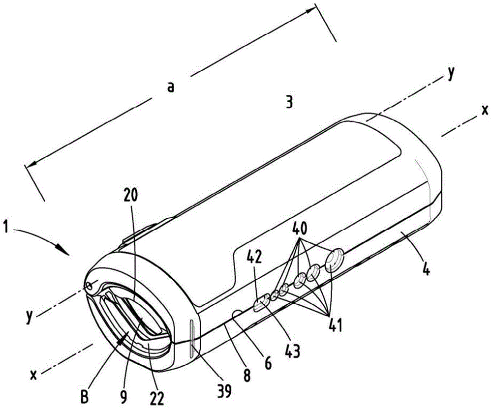
首先参考图1和图2的视图显示并且描述了用于切割波纹管2的切割设备1。A
切割设备1构造并且设计用于仅用一只手操纵,此外切割设备基本上由两个罩壳件3和4组成,在优选的设计方案中罩壳件以塑料注塑方法制成。The
罩壳件3和4形成彼此朝向的纵向边缘5至8,此外在切割设备1处于图1和图2所示的闭合位置中,纵向边缘必要时彼此贴靠地构成切割设备1的中平面M。The
罩壳件3和4可以在沿着当切割设备1的闭合位置时在中平面M中延伸的中轴线x的延伸方向观察的延伸量a(长度)上分别基本上具有连续地保持不变的横截面结构,例外是沿纵向延伸段观察在端侧的切割和导引区域B。The
当整体观察在闭合位置中的切割设备1时,罩壳件3和4的外表面必要时可以分别在端侧锥形向外逐渐变细地延伸(见图3和图4)。When the
罩壳件3和4的彼此朝向的第二纵向边缘5和7铰链作用地相互连接,其中,形成几何的枢转轴线y,枢转轴线y平行于中轴线x延伸并且因此基本上沿切割设备1的纵向延伸方向延伸。由此构成连接区域V,枢转轴线y在该连接区域中延伸。The mutually facing second
纵向边缘5至8在切割设备1的使用位置中同时限定在切割/导引区域B中出现的、由罩壳件3和4的开口部段组成的切割开口9的边界,其中此外,罩壳件3和4的确定切割开口尺寸的纵向边缘、尤其第二纵向边缘5和7,也在切割开口9的打开状态中在枢转轴线y的区域中连接,例如根据图17的视图。In the operating position of the
此外,切割设备1可以具有垂直于中平面M的延伸量b,其可以约等于沿纵向观察的延伸量a的0.25倍至0.4倍。Furthermore, the
切割设备1在闭合位置中沿中平面M延伸且横向于中轴线x或者枢转轴线y观察的延伸量c可以等于沿纵向观察的延伸量a的0.3倍至0.5倍,进一步约等于垂直于延伸量a观察的延伸量b的1.05倍至1.5倍。The extension c of the
尤其如图16中的端视图所示地,切割设备1闭合时形成整体上椭圆形的外轮廓,该外轮廓在人体工学上有利地可以通过手心面抓握。切割设备1在使用时由手指和拇指优选包围地处于手心内。As shown in particular in the end view in FIG. 16 , the
切割设备1的在闭合位置中基本上椭圆形的外轮廓在闭合位置中优选也基本上在内轮廓一侧形成相互贴靠的罩壳件3和4。The substantially elliptical outer contour of the
罩壳件3和4优选可以朝向切割设备1的打开位置的方向通过弹簧10,例如螺旋扭力弹簧施加载荷。切割设备1相应地优选在不受外部载荷的基础位置中通过弹簧挤压到打开位置中。弹簧10优选可以布置在连接区域V中,必要时居中地容纳枢转轴线y。The
此外,切割设备1可以在闭合位置中锁定,以便能节省空间地存放切割设备1。该锁定抵抗弹簧10的力。Furthermore, the
为此可以设置可推移的锁定构件11。锁定构件优选布置在连接区域V中,在此利用长孔结构12包围构成枢转轴线y的轴体13。A
锁定构件11基本上位于一个罩壳件,在此为罩壳件4的面向连接区域V的凹空部14中,其中,锁定构件11的操作面15向外露出以便操纵。The locking
锁定构件11可以在横穿中平面M的情况下横向于枢转轴线y的定向推移,以便与另一个罩壳件、在此为罩壳件3的在切割设备1的闭合位置中面对的凹空部16卡锁地咬合(见图14)。The locking
据此,另一个罩壳件、在此为罩壳件3被卡锁不能围绕枢转轴线y枢转。该卡锁位置可以通过制动机构保险。因此,在一个罩壳件的凹空部14中设计的卡止凸出部17可以咬合到锁定构件11的配属的卡止凹空部中。Accordingly, the other housing part, here the
这种卡锁也可以在按照图15的解锁位置中设置,为此,卡止凸出部17在此进入沿锁定构件11的移动方向进一步设置的卡止凹空部19中。Such a detent can also be provided in the unlocked position according to FIG. 15 , for which purpose the
在图15所示的解锁位置中,锁定构件11返回移位,使得另一个罩壳件、在此为罩壳件3的凹空部16完全露出并且因此使得罩壳件3可以围绕枢转轴线y枢转。In the unlocked position shown in FIG. 15 , the locking
在所示实施例中,切割/导引区域B设计在切割设备1的、基本上也具有具备配属的凹空部14和16的锁定构件11的端部区域中,在该切割/导引区域B中,每个罩壳件3和4基本上具有两个沿枢转轴线y的延伸方向彼此间隔地布置的第一和第二导引凸出部20、21和22、23。在相应的罩壳件3或者4的一对第一导引凸出部22、23或者一对第二导引凸出部20、21之间布置有至少一个刀刃24、25。沿枢转轴线y的延伸方向观察,罩壳件3或者4的刀刃24或者25优选相对于两个在侧向的导引凸出部20、21或者22、23均匀地间隔。In the exemplary embodiment shown, the cutting/guiding region B is designed in the end region of the
罩壳件3或者4的导引凸出部20、21或者22、23优选相同设计,尤其在向内面向切割开口9的边缘26、27方面。The
在切割设备1的闭合位置中,罩壳件3和4的边缘26和27相互对置。两个罩壳件3和4的第一导引凸出部22和23以及第二导引凸出部20和21在垂直于枢转轴线y的平面内延伸。In the closed position of the
两个罩壳件3和4的刀刃24和25可以优选相同地设计,其中,在所示的实施例中,在具有第二导引凸出部20和21的罩壳件3中仅设有一个刀刃20,而在另一个罩壳件4中在第一导引凸出部22和23之间沿周向前后依次地并且彼此间隔地设有两个刀刃25。在此也可以只是一个带有两个单独设计的切割区域的刀刃。切割区域28至30是刀刃24和25的施加切割作用的切割边缘。The cutting edges 24 and 25 of the two
优选的是,所有切割区域28至30或者所有刀刃24和25相对于相应的罩壳件3和4的周向延伸部在切割/导引区域B中偏心地布置,例如在图13中示意图所示,布置在垂直于中平面M并且横穿中轴线x的横向平面Q之外。Preferably, all cutting
切割开口9的开口尺寸d和e也沿中平面M和横向平面Q定义,其中,在纵向边缘5至8之间延伸的较大的开口尺寸d可以大约等于横向于开口尺寸d观察的开口尺寸e的1.5倍至2.5倍。根据示出的实施例,罩壳件3沿枢转轴线y的方向的延伸尺寸a(长度)可以大约等于最大的开口尺寸d的3.5倍至5倍,进一步约4倍。The opening dimensions d and e of the
刀刃24和25的切割区域28至30或者说由此构成的切割边布置在共同的、横向于中轴线x定向的并且平行于容纳一组导引凸出部的平面内,其中,根据图13中示意图,每个切割边或者每个切割区域28至30相对于中平面M围成约30°至45°的锐角α。The cutting
在可行的设计方案中,在所有刀刃24和25中锐角α是相同的,其中,相对于中平面M,刀刃24的切割区域28相对于刀刃25的切割区域29基本上镜像对称地布置,然而在此约以切割边长度的三分之一向横向平面Q的方向偏移地布置。罩壳件4中的另外的刀刃25的切割区域30相对于在图13中垂直于中平面M延伸的对称轴线z优选折叠对称地布置。在所示的实施方式中,罩壳件3中的刀刃24的切割区域28不超过对称轴线z。对称轴线z以尺寸v相对于与中轴线x相交的横向平面Q偏移,尺寸v可以大约等于切割开口9的最大的开口尺寸d的0.1倍至0.3倍。In a possible configuration, the acute angle α is the same in all cutting
切割区域28至30或者说由此构成的切割边向内向切割开口9的方向被第二导引凸出部20至23的边缘26和27超过。形成边缘26和27相对切割区域28至30的突出尺寸u,突出尺寸u可以约相当于导引凸出部20和21或者22和23沿枢转轴线y的延伸方向的距离尺寸的0.1倍至0.5倍。The cutting
从中平面M出发观察,导引凸出部20至23的边缘26和27分别具有凹形弯曲的走向,其中,罩壳件3中的第二导引凸出部20和21的第二边缘26的弯曲度大于第一导引凸出部22和23的对置的第一边缘27的弯曲度。Viewed from the mid-plane M, the
第一导引凸出部22和23的第一边缘27优选具有两个笔直延伸的侧面部段31和32,侧面部段31和32分别在保持突出尺寸u的情况下基本上平行于刀刃25的配属的切割区域29和23延伸。由此构成第一边缘27基本上V形的结构,其总体上具有在对称轴线z上的拐点。The
参照图13中的示意图,侧面部段31和32在相对于中平面M围成锐角β的情况下延伸,锐角β在数值方面基本上可以相当于角度α。横穿对称轴线z并且将侧面部段31和32连接的部段以半径r”倒圆。Referring to the schematic illustration in FIG. 13 , the
两个侧面部段31和32与中平面M相间隔地继续延伸到端部区域33、34中结束。其优选相对于中平面M平行定向地延伸,例如在切割设备1的闭合位置中保持间隔的情况下,所述间隔可以大约等于突出尺寸u。The two
罩壳件3中的第二导引凸出部20、21的第二边缘26设置有近似均匀的曲率或者说弯曲部,该弯曲部基本上产生于第二边缘26在根据图13的平面图中以半径r构成的曲线走向,半径r可以约等于切割开口9中较短的开口尺寸e的0.5倍至0.8倍。定义第二边缘26的圆周线的几何的中心W优选可以位于切割开口9外部的横向平面Q中,但仍位于对置的罩壳件4的整个横截面结构内部。半径r的值可以约相当于半径r”的值的4倍至8倍,例如约5倍。The
由此建议的圆弧优选超过对称轴线z基本直至横向平面Q地延伸,以便之后以相对前述带有半径r的部段更强烈弯曲的弧部段进行过渡。其半径r’然而相对于同样布置在横向平面Q中的中心W在此布置在切割开口9内部,从第二边缘26出发观察在中平面M的另一侧。The circular arc thus proposed preferably extends beyond the axis of symmetry z substantially up to the transverse plane Q in order to then transition with a more strongly curved arc section than the aforementioned section with radius r. Its radius r' is however arranged here inside the cutting
第二边缘26的两个具有半径r和r’的曲线部段过渡到端部区域35和36中,端部区域35和36以及对置的第一边缘27的端部区域33、34直线地相对于中平面M平行延伸地定向。The two curved sections with radii r and r′ of the
在此,直接连接在具有半径r的弯曲区域上的端部区域33近似沿中平面M延伸,而连接在具有半径r’的弯曲部段上的对置的端部区域36在保持距离尺寸f的情况下,相对于中平面M平行错移地延伸,距离尺寸f可以大约等于错移尺寸v的0.8倍至1.2倍。Here, the
端部区域33至36、尤其端部区域33、34和36分别优选既不接触也不穿透中平面M地布置,尽管这些端部区域中的至少一个端部区域,例如端部区域35也可以与中平面M相交地结束。The
相对于垂直到中平面M上的投影,第二边缘26的直线地、平行于中平面M结束的端部区域35和36在第一边缘27的以角度β延伸的侧面部段31和32的延伸段以内延伸(这是相对于切割设备1的闭合位置)。此外,相对于上述投影,由此构成罩壳件3的第二导引凸出部20、21的曲线成形的第二边缘26相对于罩壳件4的第一导引凸出部22、23的基本上V形延伸的第一边缘27的完全覆盖。With respect to a projection perpendicular to the mid-plane M, the
为了切割波纹管,在罩壳件3和4围绕枢转轴线y枢转打开之后,波纹管插入切割设备1中,使得波纹管的纵轴线沿切割设备1的中轴线x定向地布置在切割设备1中。For cutting the bellows, after the
通过持握切割设备1的手从外部的作用,导致罩壳件3和4围绕枢转轴线y相互靠拢偏转,由此,导引凸出部20至23伸入两个沿波纹管2的纵向优选直接前后依次的波谷37中。这种伸入可以在沿相应的边缘26或27的整个沿周向观察的长度上进行,但是必要时也可以仅在局部。The action of the hand holding the
导引凸出部22至23,尤其导引凸出部的边缘26和27的上述几何结构有利地允许切割设备在不同直径的波纹管2情况下使用。The above-described geometry of the guide lugs 22 to 23 , in particular the
尤其如图18中的剖视图所示,当波纹管2在切割设备1中导引时,该布置方式进一步如此实现,使得刀刃24和25配属波纹管2的在用于导引的波谷37之间成形的波峰38。通过持握罩壳件3的手从外部相应地加压,由此在切割设备1围绕其中轴线x的转动和相应地围绕波纹管2的中轴线的转动叠加的情况下,刀刃24和25被压入波纹管材料中,因此在波峰38的区域中切入波纹管2。由此能够由于提供的导引实现优选基本上在垂直于波纹管纵轴线延伸的平面中精确的切割。As shown in particular in the sectional view in FIG. 18 , when the
为了切割设备1的有利的使用,在切割设备1的壁部外侧标记刀刃24和25的轴向位置。在所示实施例中,这种切口39形式的标记设置在罩壳件3和4的外周侧,配属于罩壳件的背离枢转轴线y的纵向边缘6和8。根据图5中的视图,该切口39相应地在切割设备1的闭合位置中跨过同时也表现为分离面的中平面M。For an advantageous use of the
在执行分离切割之后波纹管2的被切掉的部段至少部分地在切割设备1中容纳和捕获。这进一步简化了使用。此外,切割/导引区域D也优选直接配属于切割设备1的端部区域地布置,由此有利地在空间上难以触及的区域中实现波纹管的切割。After the separating cut has been carried out, the severed section of the
此外,切割设备1可以在背离枢转轴线y的第一纵向边缘6和8的区域中设有多个用于去除电缆绝缘层,尤其用于去除单个电线的绝缘层的刀刃40、41。因此根据所示的实施例,沿切割设备1的纵向延伸段可以设计前后依次并且彼此间隔的多个刀刃40、41,用于去除不同直径的电缆或电线的绝缘层。在此,罩壳件3的第一纵向边缘6中的刀刃40分别与罩壳件4的第一纵向边缘8中的刀刃41相对置地布置。刀刃40及40配设有从纵向边缘出发观察凹形的切割边,该切割边在切割设备1闭合时与对置的刀刃配合作用,构成相应于线材直径的圆形的刀刃。该切割边沿枢转轴线y的延伸方向延伸。Furthermore, the
在所示实施例中设有五个这种剥线刀刃。In the exemplary embodiment shown, five such stripping blades are provided.
此外并排地并且因此同样在能相向枢转的第一纵向边缘6和8区域中布置有另外的剥线刀刃42、43,剥线刀刃42、43分别具有优选笔直延伸并且在闭合位置中平行于中平面M延伸的切割边。该切割边在闭合位置中可以相互贴靠。In addition, further stripping
所有刀刃40至43以及刀刃24和25都可以在切割/导引区域B中,此外优选导引凸出部20至23也在罩壳件3、4的材料中固定,这例如在塑料注塑过程中制造罩壳件3、4时由于包封注塑优选设计为钢构件的刀刃和凸出部而实现。All cutting edges 40 to 43 as well as cutting
附图标记列表List of reference signs
1 切割设备1 cutting equipment
2 波纹管2 bellows
3 罩壳件3 housing parts
4 罩壳件4 housing parts
5 第二纵向边缘5 Second longitudinal edge
6 第一纵向边缘6 First longitudinal edge
7 第二纵向边缘7 Second longitudinal edge
8 第一纵向边缘8 First longitudinal edge
9 切割开口9 cut opening
10 弹簧10 springs
11 锁定构件11 Locking member
12 长孔结构12 long hole structure
13 轴体13 axis body
14 凹空部14 hollow part
15 操作面15 Operation surface
16 凹空部16 hollow part
17 卡止凸出部17 Locking protrusion
18 卡止凹空部18 Detent recess
19 卡止凹空部19 Detent recess
20 第二导引凸出部20 Second guide protrusion
21 第二导引凸出部21 Second guide protrusion
22 第一导引凸出部22 First guide protrusion
23 第一导引凸出部23 First guide protrusion
24 刀刃24 blades
25 刀刃25 blades
26 第二边缘26 second edge
27 第一边缘27 First Edge
28 切割区域28 cutting area
29 切割区域29 cutting area
30 切割区域30 cutting area
31 侧面部段31 side section
32 侧面部段32 side sections
33 端部区域33 end area
34 端部区域34 end area
35 端部区域35 end area
36 端部区域36 end area
37 波谷37 trough
38 波峰38 crests
39 切口39 cuts
40 刀刃40 blades
41 刀刃41 blade
42 剥线刀刃42 Stripping blade
43 剥线刀刃43 Stripping blade
a 延伸量a elongation
b 延伸量b elongation
c 延伸量c elongation
d 开口尺寸d opening size
e 开口尺寸e Opening size
f 距离尺寸f distance dimension
r 半径r radius
r’ 半径r' radius
r” 半径r" radius
u 突出尺寸u Protrusion size
v 偏移尺寸v Offset size
x 中轴线x axis
y 枢转轴线y pivot axis
z 对称轴线z axis of symmetry
B 切割/导引区域B Cutting/guiding area
M 中平面M mid-plane
Q 横向平面Q Transverse plane
V 连接区域V connection area
W 中心W center
W’ 中心W' center
α 角度alpha angle
β 角度beta angle
Claims (19)
Applications Claiming Priority (3)
| Application Number | Priority Date | Filing Date | Title |
|---|---|---|---|
| DE102017129725.1A DE102017129725A1 (en) | 2017-12-13 | 2017-12-13 | Cutting device for cutting corrugated tubes and guide projections in such a cutting device |
| DE102017129725.1 | 2017-12-13 | ||
| PCT/EP2018/084561 WO2019115613A1 (en) | 2017-12-13 | 2018-12-12 | Cutting device for cutting corrugated pipes to length and guide projections in such a cutting device |
Publications (2)
| Publication Number | Publication Date |
|---|---|
| CN111448024A CN111448024A (en) | 2020-07-24 |
| CN111448024B true CN111448024B (en) | 2023-03-14 |
Family
ID=64959288
Family Applications (1)
| Application Number | Title | Priority Date | Filing Date |
|---|---|---|---|
| CN201880079266.6A Active CN111448024B (en) | 2017-12-13 | 2018-12-12 | Cutting device for cutting corrugated tubing and guide projection in a cutting device |
Country Status (5)
| Country | Link |
|---|---|
| EP (1) | EP3723928B1 (en) |
| CN (1) | CN111448024B (en) |
| DE (1) | DE102017129725A1 (en) |
| TW (1) | TWI804542B (en) |
| WO (1) | WO2019115613A1 (en) |
Families Citing this family (3)
| Publication number | Priority date | Publication date | Assignee | Title |
|---|---|---|---|---|
| DE102021105343A1 (en) | 2021-03-05 | 2022-09-08 | Knipex-Werk C. Gustav Putsch Kg | Cutting device for cutting pipes or sleeves to length |
| DE102021129943B4 (en) | 2021-11-17 | 2024-08-01 | Viessmann Climate Solutions Se | Corrugated pipe cutting device |
| DE202023002040U1 (en) * | 2023-09-27 | 2023-11-16 | Flexa Gmbh & Co Produktion Und Vertrieb Kg | Cutting tool for corrugated hoses |
Citations (4)
| Publication number | Priority date | Publication date | Assignee | Title |
|---|---|---|---|---|
| EP1295688A2 (en) * | 2001-09-19 | 2003-03-26 | Mapress GmbH & Co. KG | Apparatus and method for cutting tubes |
| DE202014101596U1 (en) * | 2014-04-04 | 2014-04-29 | Klaus Knipping Gmbh | Device for stripping coaxial cables |
| CN106001737A (en) * | 2016-07-20 | 2016-10-12 | 焦祥静 | Guide device for pipe cutter |
| CN106475630A (en) * | 2015-08-31 | 2017-03-08 | 中国石油天然气股份有限公司 | Multi-knife pipe cutter |
Family Cites Families (7)
| Publication number | Priority date | Publication date | Assignee | Title |
|---|---|---|---|---|
| DE2159744A1 (en) * | 1971-12-02 | 1973-06-07 | Alf Mattsson | DEVICE FOR CUTTING PIPES |
| GB2207377A (en) * | 1987-07-29 | 1989-02-01 | Edward Donald Smallwood | Plastic pipe cutter and chamfer tool |
| CH682471A5 (en) * | 1990-10-25 | 1993-09-30 | Lancomp Ag | Cutting appts. for grooved profile plastic tube - comprises flexible blade guide around tube, guiding comb engaging in groove and blade |
| TW301272U (en) * | 1995-06-01 | 1997-03-21 | Bae Hwan Ind Co Ltd | Flexible corrugated pipe cutter |
| DE29711774U1 (en) | 1997-07-04 | 1997-09-18 | Josef Schlemmer GmbH, 85586 Poing | Hand cutter for cutting corrugated pipes |
| US6725533B1 (en) * | 2000-03-20 | 2004-04-27 | Lemco Tool Corporation | Cable stripping tool |
| US9707691B2 (en) * | 2013-01-14 | 2017-07-18 | RL Tools, L.L.C. | Conduit cutting tools and conduit cutting tool operational methods |
-
2017
- 2017-12-13 DE DE102017129725.1A patent/DE102017129725A1/en not_active Withdrawn
-
2018
- 2018-12-12 CN CN201880079266.6A patent/CN111448024B/en active Active
- 2018-12-12 WO PCT/EP2018/084561 patent/WO2019115613A1/en not_active Ceased
- 2018-12-12 EP EP18830173.3A patent/EP3723928B1/en active Active
- 2018-12-13 TW TW107145042A patent/TWI804542B/en active
Patent Citations (4)
| Publication number | Priority date | Publication date | Assignee | Title |
|---|---|---|---|---|
| EP1295688A2 (en) * | 2001-09-19 | 2003-03-26 | Mapress GmbH & Co. KG | Apparatus and method for cutting tubes |
| DE202014101596U1 (en) * | 2014-04-04 | 2014-04-29 | Klaus Knipping Gmbh | Device for stripping coaxial cables |
| CN106475630A (en) * | 2015-08-31 | 2017-03-08 | 中国石油天然气股份有限公司 | Multi-knife pipe cutter |
| CN106001737A (en) * | 2016-07-20 | 2016-10-12 | 焦祥静 | Guide device for pipe cutter |
Also Published As
| Publication number | Publication date |
|---|---|
| EP3723928B1 (en) | 2022-06-22 |
| DE102017129725A1 (en) | 2019-06-13 |
| CN111448024A (en) | 2020-07-24 |
| EP3723928A1 (en) | 2020-10-21 |
| TW201927500A (en) | 2019-07-16 |
| WO2019115613A1 (en) | 2019-06-20 |
| TWI804542B (en) | 2023-06-11 |
Similar Documents
| Publication | Publication Date | Title |
|---|---|---|
| CN111448024B (en) | Cutting device for cutting corrugated tubing and guide projection in a cutting device | |
| US6134994A (en) | Pliers with ergonomic handles | |
| TWI710188B (en) | Stripping tool | |
| EP3280570A1 (en) | Pair of scissors, particularly for cutting hair | |
| US20130326882A1 (en) | Hand tool including a wire strippers | |
| CN101189100B (en) | Hand wrench for driving cylindrical elements | |
| WO2019079287A1 (en) | Tube slitter with off-axis hinge | |
| TW202235240A (en) | Cutting equipment for cutting pipes or casings to length | |
| JP2016100937A (en) | Armor rod attachment/detachment tool | |
| US20160288352A1 (en) | Knife having removable blade guard | |
| JP6030428B2 (en) | Fish pincer | |
| AU2436092A (en) | Interdental brush holder | |
| US2493941A (en) | Armored cable cutter | |
| US8739594B2 (en) | Electrical connector crimping plier tool | |
| US20220203505A1 (en) | Hand tool structure | |
| US11110618B2 (en) | Hand-held shearing device | |
| JP2010506637A (en) | Working pliers for jaw orthopedic and dental techniques | |
| JP7423038B2 (en) | scissors for endoscope | |
| JP3150528U (en) | Pliers | |
| CN211841597U (en) | hand tool structure | |
| JP2024154448A (en) | Cutting Tools | |
| WO2019212039A1 (en) | Gripping tool for indirect live-line working | |
| JP6170412B2 (en) | Masking cap removal device | |
| US2637903A (en) | Flexible conduit cutter | |
| US20190283263A1 (en) | Novel Shearing Device |
Legal Events
| Date | Code | Title | Description |
|---|---|---|---|
| PB01 | Publication | ||
| PB01 | Publication | ||
| SE01 | Entry into force of request for substantive examination | ||
| SE01 | Entry into force of request for substantive examination | ||
| GR01 | Patent grant | ||
| GR01 | Patent grant |