CN111496552A - Differential positioning device - Google Patents
Differential positioning device Download PDFInfo
- Publication number
- CN111496552A CN111496552A CN202010446434.XA CN202010446434A CN111496552A CN 111496552 A CN111496552 A CN 111496552A CN 202010446434 A CN202010446434 A CN 202010446434A CN 111496552 A CN111496552 A CN 111496552A
- Authority
- CN
- China
- Prior art keywords
- screw
- aforementioned
- driving source
- fine
- sliding table
- Prior art date
- Legal status (The legal status is an assumption and is not a legal conclusion. Google has not performed a legal analysis and makes no representation as to the accuracy of the status listed.)
- Granted
Links
- 230000007246 mechanism Effects 0.000 claims abstract description 20
- 230000005540 biological transmission Effects 0.000 claims description 4
- 238000006073 displacement reaction Methods 0.000 description 9
- 238000010586 diagram Methods 0.000 description 8
- 239000011295 pitch Substances 0.000 description 6
- XEEYBQQBJWHFJM-UHFFFAOYSA-N Iron Chemical compound [Fe] XEEYBQQBJWHFJM-UHFFFAOYSA-N 0.000 description 2
- 230000008878 coupling Effects 0.000 description 2
- 238000010168 coupling process Methods 0.000 description 2
- 238000005859 coupling reaction Methods 0.000 description 2
- 230000033001 locomotion Effects 0.000 description 2
- 238000003754 machining Methods 0.000 description 2
- 229910052742 iron Inorganic materials 0.000 description 1
- 239000000463 material Substances 0.000 description 1
- 239000002184 metal Substances 0.000 description 1
- 229910052751 metal Inorganic materials 0.000 description 1
- 238000000034 method Methods 0.000 description 1
Images


Classifications
-
- B—PERFORMING OPERATIONS; TRANSPORTING
- B23—MACHINE TOOLS; METAL-WORKING NOT OTHERWISE PROVIDED FOR
- B23Q—DETAILS, COMPONENTS, OR ACCESSORIES FOR MACHINE TOOLS, e.g. ARRANGEMENTS FOR COPYING OR CONTROLLING; MACHINE TOOLS IN GENERAL CHARACTERISED BY THE CONSTRUCTION OF PARTICULAR DETAILS OR COMPONENTS; COMBINATIONS OR ASSOCIATIONS OF METAL-WORKING MACHINES, NOT DIRECTED TO A PARTICULAR RESULT
- B23Q1/00—Members which are comprised in the general build-up of a form of machine, particularly relatively large fixed members
- B23Q1/25—Movable or adjustable work or tool supports
- B23Q1/26—Movable or adjustable work or tool supports characterised by constructional features relating to the co-operation of relatively movable members; Means for preventing relative movement of such members
Landscapes
- Engineering & Computer Science (AREA)
- Mechanical Engineering (AREA)
- Control Of Position Or Direction (AREA)
- Machine Tool Units (AREA)
Abstract
一种差动定位装置,其特征在于包括底座、粗驱动源、第一螺杆、滑台、精驱动源、第二螺杆、移动台及位置感应模块,第一螺杆与前述粗驱动源驱动连接,该第一螺杆上设有用于制动第一螺杆的抱闸;第二螺杆轴向中空供前述第一螺杆贯穿设置并具有与前述第一螺杆配合的第一螺母,该第二螺杆与前述的精驱动源通过变速机构驱动连接;移动台能滑动地设于前述滑台上并具有与前述第二螺杆驱动配合的第二螺母。先用粗定位发挥效率,进而用差动式精定位,发挥精度,通过两套螺旋部件有机结合的运动达到效率和精度的兼顾。
A differential positioning device is characterized in that it comprises a base, a rough driving source, a first screw, a sliding table, a fine driving source, a second screw, a moving table and a position sensing module, and the first screw is drivingly connected with the aforementioned rough driving source, The first screw rod is provided with a brake for braking the first screw rod; the second screw rod is axially hollow for the first screw rod to pass through and has a first nut matched with the aforementioned first screw rod, and the second screw rod is connected with the aforementioned first screw rod. The fine driving source is driven and connected through a speed change mechanism; the moving table is slidably arranged on the sliding table and has a second nut that is drivingly matched with the second screw. Coarse positioning is used to exert efficiency first, and then differential fine positioning is used to exert precision, and both efficiency and accuracy can be achieved through the organic combination of two sets of helical components.
Description
技术领域technical field
本发明涉及一种定位机构,该定位机构可以应用于精密加工设备。The present invention relates to a positioning mechanism, which can be applied to precision machining equipment.
背景技术Background technique
精准的定位机构在很多机械设备上都要用到,常见的就是机床上,直接影响加工精度,目前常见的定位机构一般采用单一电机驱动螺杆(又称螺杆)来实现精准定位,这种定位机构存在定位效率与定位精度上的矛盾,即定位效率高则精度低,而精度高则定位效率低,即工作台从高速移动到接近目标时要突然降速就会发生抖动,引起定位的不稳定同时也给控制带来了困难,定位精度及定位效率难以达到和谐统一。Precise positioning mechanisms are used in many mechanical equipment. The most common one is on machine tools, which directly affects the machining accuracy. At present, common positioning mechanisms generally use a single motor-driven screw (also known as screw) to achieve precise positioning. This positioning mechanism There is a contradiction between positioning efficiency and positioning accuracy, that is, high positioning efficiency means low precision, and high precision means low positioning efficiency, that is, when the worktable moves from high speed to approaching the target, it will shake when the speed suddenly decelerates, causing unstable positioning. At the same time, it also brings difficulties to the control, and it is difficult to achieve a harmonious unity of positioning accuracy and positioning efficiency.
发明内容SUMMARY OF THE INVENTION
本发明所要解决的技术问题是针对上述的技术现状而提供一种兼顾效率和精度的差动定位装置。The technical problem to be solved by the present invention is to provide a differential positioning device that takes into account both efficiency and accuracy in view of the above-mentioned technical situation.
本发明解决上述技术问题所采用的第一种技术方案为:一种差动定位装置,其特征在于包括The first technical solution adopted by the present invention to solve the above technical problems is: a differential positioning device, which is characterized by comprising:
底座;base;
粗驱动源,设于前述底座上;The rough driving source is arranged on the aforementioned base;
第一螺杆,能转动地设于前述底座上并与前述粗驱动源驱动连接,该第一螺杆上设有用于制动第一螺杆的抱闸;The first screw rod is rotatably arranged on the aforementioned base and is drivingly connected with the aforementioned rough driving source, and the first screw rod is provided with a holding brake for braking the first screw rod;
滑台,能滑动地设于前述底座上;a sliding table, which can be slidably arranged on the aforementioned base;
精驱动源,设于前述滑台上;The fine drive source is set on the aforementioned sliding table;
第二螺杆,轴向中空供前述第一螺杆贯穿设置并具有与前述第一螺杆配合的第一螺母,该第二螺杆与前述的精驱动源通过变速机构驱动连接;a second screw rod, which is axially hollow for the aforementioned first screw rod to pass through and has a first nut matched with the aforementioned first screw rod, and the second screw rod is drivingly connected with the aforementioned fine driving source through a speed change mechanism;
移动台,能滑动地设于前述滑台上并具有与前述第二螺杆驱动配合的第二螺母;以及a moving table, which is slidably arranged on the sliding table and has a second nut that is drivingly matched with the second screw rod; and
位置感应模块,用于感应移动台的位置;Position sensing module for sensing the position of the mobile station;
前述第一螺杆的外螺纹和第二螺杆的螺纹旋转方向相同,并且,前述第一螺杆的外螺纹和第二螺杆的外螺纹的螺距差大于零。The external thread of the first screw and the screw of the second screw rotate in the same direction, and the pitch difference between the external thread of the first screw and the external thread of the second screw is greater than zero.
进一步,所述的粗驱动源为粗定位电机,所述的精驱动源为精定位电机。Further, the coarse driving source is a coarse positioning motor, and the fine driving source is a fine positioning motor.
进一步,该装置还包括控制板,该控制板与粗定位电机、精定位电机、抱闸及位置感应模块连接。Further, the device further includes a control board, which is connected with the coarse positioning motor, the fine positioning motor, the holding brake and the position sensing module.
作为优选,所述的移动台通过磁吸机构与滑台能脱卸地连接,并且,所述的控制板与磁吸结构控制连接。Preferably, the moving table is detachably connected to the sliding table through a magnetic attraction mechanism, and the control board is controlled and connected to the magnetic attraction mechanism.
所述的粗驱动源为第一手动摇柄,所述的精驱动源为第二手动摇柄。进一步,于该装置还包括控制板,该控制板与抱闸和位置感应模块连接。The rough driving source is the first manual crank handle, and the fine driving source is the second manual crank handle. Further, the device further includes a control board, the control board is connected with the holding brake and the position sensing module.
作为优选,所述的变速机构包括设于精驱动源上的第一齿轮和设于第二螺杆上的第二齿轮,前述的第一齿轮和第二齿轮啮合传动。Preferably, the speed change mechanism includes a first gear set on the fine drive source and a second gear set on the second screw rod, and the aforementioned first gear and the second gear mesh for transmission.
进一步,所述底座上沿着第一螺杆的长度方向设有导轨,所述移动台的下端面设有第一导向槽,对应地,所述滑台的下端面具有与前述导轨导向配合的第二导向槽,上端面具有与前述第一导向槽导向配合的导向筋。Further, the base is provided with a guide rail along the length direction of the first screw, the lower end surface of the moving table is provided with a first guide groove, and correspondingly, the lower end surface of the sliding table has a first guide groove for guiding and matching with the aforementioned guide rail. There are two guide grooves, and the upper end surface has a guide rib that guides and cooperates with the first guide groove.
本发明解决上述技术问题所采用的第二种技术方案为:一种差动定位装置,其特征在于包括The second technical solution adopted by the present invention to solve the above technical problems is: a differential positioning device, which is characterized by comprising:
底座;base;
粗驱动源,设于前述底座上;The rough driving source is arranged on the aforementioned base;
第一螺杆,能转动地设于前述底座上并与前述粗驱动源驱动连接,该第一螺杆上设有用于制动第一螺杆的抱闸;The first screw rod is rotatably arranged on the aforementioned base and is drivingly connected with the aforementioned rough driving source, and the first screw rod is provided with a holding brake for braking the first screw rod;
滑台,能滑动地设于前述底座上;a sliding table, which can be slidably arranged on the aforementioned base;
精驱动源,设于前述滑台上;The fine drive source is set on the aforementioned sliding table;
第二螺杆,轴向中空供前述第一螺杆贯穿设置并具有与前述第一螺杆配合的第一螺母,该第二螺杆与前述的精驱动源通过变速机构驱动连接;a second screw rod, which is axially hollow for the aforementioned first screw rod to pass through and has a first nut matched with the aforementioned first screw rod, and the second screw rod is drivingly connected with the aforementioned fine driving source through a speed change mechanism;
移动台,设于前述滑台上并能随滑台一起来回移动,该移动台具有与前述第二螺杆驱动配合的第二螺母;以及a moving table, which is arranged on the sliding table and can move back and forth together with the sliding table, the moving table has a second nut that is drivingly matched with the second screw rod; and
位置感应模块,用于感应移动台的位置;Position sensing module for sensing the position of the mobile station;
前述第一螺杆的外螺纹和第二螺杆的螺纹旋转方向相同,并且,前述第一螺杆的外螺纹和第二螺杆的外螺纹的螺距差大于零。The external thread of the first screw and the screw of the second screw rotate in the same direction, and the pitch difference between the external thread of the first screw and the external thread of the second screw is greater than zero.
进一步,所述的粗驱动源为粗定位电机,所述的精驱动源为精定位电机,前述的粗定位电机、精定位电机、抱闸及位置感应模块与一控制板控制连接。Further, the coarse driving source is a coarse positioning motor, the fine driving source is a fine positioning motor, and the aforementioned coarse positioning motor, fine positioning motor, brake and position sensing modules are controlled and connected to a control board.
与现有技术相比,本发明的优点在于:先用粗定位发挥效率,进而用差动式精定位,发挥精度,通过两套螺旋部件有机结合的运动达到效率和精度的兼顾。Compared with the prior art, the present invention has the advantages that: first use coarse positioning to exert efficiency, then use differential fine positioning to exert precision, and achieve both efficiency and accuracy through the organic combination of two sets of helical components.
附图说明Description of drawings
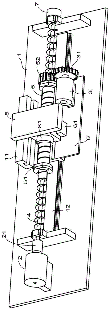
图1为实施例1结构示意图。FIG. 1 is a schematic structural diagram of Embodiment 1. FIG.
图2为实施例1另一视角结构示意图。FIG. 2 is a schematic structural diagram of Embodiment 1 from another viewing angle.
图3为实施例1中部分分解图。FIG. 3 is a partial exploded view of Embodiment 1. FIG.
图4为实施例1控制原理图。FIG. 4 is a control principle diagram of Embodiment 1. FIG.
图5为实施例2结构示意图。FIG. 5 is a schematic structural diagram of
图6为实施例3结构示意图。FIG. 6 is a schematic structural diagram of
图7为实施例3另一视角结构示意图。FIG. 7 is a schematic structural diagram of another viewing angle of
图8为实施例3控制原理图。FIG. 8 is a control principle diagram of
图9为实施例4结构示意图。FIG. 9 is a schematic structural diagram of
具体实施方式Detailed ways
以下结合附图实施例对本发明作进一步详细描述。The present invention will be further described in detail below with reference to the embodiments of the accompanying drawings.
实施例1,如图1、图2和图4所示,本实施例中的差动定位装置包括底座1、粗定位电机2、第一螺杆4、滑台6、精定位电机3、第二螺杆5、移动台8、位置感应模块11及控制板100。Embodiment 1, as shown in Figures 1, 2 and 4, the differential positioning device in this embodiment includes a base 1, a
粗定位电机2设于底座1上;第一螺杆4能转动地设于底座1上并与粗定位电机2通过联轴器21驱动连接,该第一螺杆4上设有用于制动第一螺杆4的抱闸7;滑台6能滑动地设于底座1上;精定位电机3设于滑台6上。The
第二螺杆5轴向中空供第一螺杆4贯穿设置并具有与第一螺杆4配合的第一螺母51,该第二螺杆5与精定位电机通过变速机构驱动连接;本实施例中的变速机构包括设于精定位电机上的第一齿轮31和设于第二螺杆5上的第二齿轮52,第一齿轮31和第二齿轮52啮合传动。The
移动台8通过磁吸机构能脱卸地设于滑台6上并能来回移动,本实施例中的磁吸机构包括电磁铁61,移动台8采用与电磁铁能磁吸的铁制材料,当然也可以移动台8上设置与电磁铁磁吸的金属板,保证在电磁铁61在通电状态下能磁吸。移动台8具有与第二螺杆5驱动配合的第二螺母81。The mobile table 8 is detachably mounted on the sliding table 6 through a magnetic attraction mechanism and can move back and forth. The magnetic attraction mechanism in this embodiment includes an
位置感应模块11设于底座1上,用于感应移动台8的位置,本实施例中的位置感应模块11具体可以采用红外感应器、激光感应器或光栅感应器等。The
第一螺杆4的外螺纹和第二螺杆5的外螺纹旋转方向相同,并且,第一螺杆4的外螺纹和第二螺杆5的外螺纹的螺距差大于零。The external thread of the
结合图4所示,该控制板与电磁铁61、粗定位电机2、精定位电机3、抱闸7及位置感应模块11控制连接。As shown in FIG. 4 , the control board is controlled and connected with the
结合图3所示,底座1上沿着第一螺杆4的长度方向设有导轨12,移动台8的下端面设有第一导向槽82,对应地,滑台6的下端面具有与导轨12导向配合的第二导向槽62,上端面具有与第一导向槽82导向配合的导向筋63。滑台6在底座1上通过导轨12和第二导向槽62实现滑动配合。移动台8在滑台6上通过第一导向槽82和导向筋63实现滑动配合。As shown in FIG. 3 , the base 1 is provided with a
工作原理:working principle:
初始状态下电磁铁61与移动台8保持磁吸,这时移动台和滑台是固定一体的。In the initial state, the
粗定位电机2运转,带动第一螺杆4转动,第一螺杆4带动与第一螺母51和第二螺杆5旋转,第二螺杆5与第二螺母81,从而带动移动台8和滑台6快速向前移动,当接近目标达到设定的阈值时,粗定位电机2停止工作,电磁铁61失电,移动台8和滑台6脱开,同时,抱闸7制动第一螺杆4,启动精定位电机3,精定位电机3通过第一齿轮31和第二齿轮52驱动第二螺杆5继续转动,这时第二螺杆5与第二螺母81配合,使移动台8发生一次位移,第二螺杆5上的第一螺母51与第一螺杆配合,使移动台8发生二次位移,一次位移和二次位移方向相反,两者之间存在位移差值,实现差动,最后,移动台8通过差动配合后将位置反馈的信息移动到目标位置停止。The operation of the
精定位电机的定位精度计算:
先用粗定位发挥效率,进而用精定位,发挥精度,通过两套螺旋部件有机结合的运动达到效率和精度的兼顾。First, use coarse positioning to exert efficiency, and then use fine positioning to exert precision, and achieve both efficiency and accuracy through the organic combination of two sets of helical components.
本实施例可以应用于高精度的机床上。This embodiment can be applied to a high-precision machine tool.
实施例2,如图5所示,本实施例用第一手动摇柄91替代粗定位电机,第二手动摇柄92替代精定位电机。其他结构和基本工作原理参考实施例1。本实施例可以应用于显微镜上。
实施例3,如图6和图7所示,本实施例中本实施例中的差动定位装置包括底座1、粗定位电机2、第一螺杆4、滑台6、精定位电机3、第二螺杆5、移动台8、位置感应模块11及控制板100。
粗定位电机2设于底座1上;第一螺杆4能转动地设于底座1上并与粗定位电机2通过联轴器21驱动连接,该第一螺杆4上设有用于制动第一螺杆4的抱闸7;滑台6能滑动地设于底座1上;具体地,底座1上沿着第一螺杆4的长度方向设有导轨12,滑台6的下端面具有与导轨12导向配合的导向槽。滑台6在底座1上通过导轨12和导向槽实现滑动配合。精定位电机3设于滑台6上。The
第二螺杆5轴向中空供第一螺杆4贯穿设置并具有与第一螺杆4配合的第一螺母51,该第二螺杆5与精定位电机3通过变速机构驱动连接;本实施例中的变速机构包括设于精定位电机上的第一齿轮31和设于第二螺杆5上的第二齿轮52,第一齿轮31和第二齿轮52啮合传动。The
移动台8固定设于滑台6上并能随滑台来回移动。移动台8具有与第二螺杆5驱动配合的第二螺母81。The moving table 8 is fixed on the sliding table 6 and can move back and forth with the sliding table. The moving table 8 has a
位置感应模块11设于底座1上,用于感应移动台8的位置,本实施例中的位置感应模块11具体可以采用红外感应器、激光感应器或光栅感应器等。The
第一螺杆4的外螺纹和第二螺杆5的外螺纹旋转方向相同,并且,第一螺杆4的外螺纹和第二螺杆5的外螺纹的螺距差大于零。The external thread of the
结合图8所示,该控制板与粗定位电机2、精定位电机3、抱闸7及位置感应模块11控制连接。As shown in FIG. 8 , the control board is controlled and connected with the
工作原理:working principle:
粗定位电机2运转,带动第一螺杆4转动,第一螺杆4带动与第一螺母51和第二螺杆5旋转,第二螺杆5与第二螺母81,从而带动移动台8和滑台6快速向前移动,当接近目标达到设定的阈值时,粗定位电机2停止工作,抱闸7制动第一螺杆4。The operation of the
启动精定位电机3,精定位电机3通过第一齿轮31和第二齿轮52驱动第二螺杆5继续转动,这时第二螺杆5与第二螺母81配合,使移动台8发生一次位移,同时,第二螺杆5上的第一螺母51与第一螺杆配合,使移动台8发生二次位移,一次位移和二次位移方向相反,两者之间存在位移差值,实现差动,最后,移动台8通过差动配合后将位置反馈的信息移动到目标位置停止。The
实施例4,如图9所示,本实施例用第一手动摇柄91替代粗定位电机,第二手动摇柄92替代精定位电机。其他结构和基本工作原理参考实施例3。本实施例可以应用于显微镜上。
Claims (10)
Priority Applications (1)
| Application Number | Priority Date | Filing Date | Title |
|---|---|---|---|
| CN202010446434.XA CN111496552B (en) | 2020-05-25 | 2020-05-25 | Differential positioning device |
Applications Claiming Priority (1)
| Application Number | Priority Date | Filing Date | Title |
|---|---|---|---|
| CN202010446434.XA CN111496552B (en) | 2020-05-25 | 2020-05-25 | Differential positioning device |
Publications (2)
| Publication Number | Publication Date |
|---|---|
| CN111496552A true CN111496552A (en) | 2020-08-07 |
| CN111496552B CN111496552B (en) | 2024-08-23 |
Family
ID=71865390
Family Applications (1)
| Application Number | Title | Priority Date | Filing Date |
|---|---|---|---|
| CN202010446434.XA Active CN111496552B (en) | 2020-05-25 | 2020-05-25 | Differential positioning device |
Country Status (1)
| Country | Link |
|---|---|
| CN (1) | CN111496552B (en) |
Cited By (2)
| Publication number | Priority date | Publication date | Assignee | Title |
|---|---|---|---|---|
| CN112701848A (en) * | 2020-12-18 | 2021-04-23 | 张利峰 | Braking device driven by motor |
| CN112719937A (en) * | 2020-12-18 | 2021-04-30 | 宁波职业技术学院 | Control mechanism capable of carrying out accurate position adjustment |
Citations (5)
| Publication number | Priority date | Publication date | Assignee | Title |
|---|---|---|---|---|
| JP2007198909A (en) * | 2006-01-26 | 2007-08-09 | Nsk Ltd | Coarse / fine positioning device |
| CN102699693A (en) * | 2012-06-20 | 2012-10-03 | 江南大学 | Micron-sized tool apron adjusting mechanism |
| CN205798959U (en) * | 2016-07-05 | 2016-12-14 | 伯肯森自动化技术(上海)有限公司 | A kind of workpiece automatic precision detent mechanism |
| CN206803951U (en) * | 2017-04-27 | 2017-12-26 | 杭州电子科技大学 | A kind of differential type measurer for thickness |
| CN212470554U (en) * | 2020-05-25 | 2021-02-05 | 俞富春 | Differential positioning device |
-
2020
- 2020-05-25 CN CN202010446434.XA patent/CN111496552B/en active Active
Patent Citations (5)
| Publication number | Priority date | Publication date | Assignee | Title |
|---|---|---|---|---|
| JP2007198909A (en) * | 2006-01-26 | 2007-08-09 | Nsk Ltd | Coarse / fine positioning device |
| CN102699693A (en) * | 2012-06-20 | 2012-10-03 | 江南大学 | Micron-sized tool apron adjusting mechanism |
| CN205798959U (en) * | 2016-07-05 | 2016-12-14 | 伯肯森自动化技术(上海)有限公司 | A kind of workpiece automatic precision detent mechanism |
| CN206803951U (en) * | 2017-04-27 | 2017-12-26 | 杭州电子科技大学 | A kind of differential type measurer for thickness |
| CN212470554U (en) * | 2020-05-25 | 2021-02-05 | 俞富春 | Differential positioning device |
Cited By (3)
| Publication number | Priority date | Publication date | Assignee | Title |
|---|---|---|---|---|
| CN112701848A (en) * | 2020-12-18 | 2021-04-23 | 张利峰 | Braking device driven by motor |
| CN112719937A (en) * | 2020-12-18 | 2021-04-30 | 宁波职业技术学院 | Control mechanism capable of carrying out accurate position adjustment |
| CN112719937B (en) * | 2020-12-18 | 2022-04-12 | 宁波职业技术学院 | Control mechanism capable of carrying out accurate position adjustment |
Also Published As
| Publication number | Publication date |
|---|---|
| CN111496552B (en) | 2024-08-23 |
Similar Documents
| Publication | Publication Date | Title |
|---|---|---|
| US9266193B2 (en) | Infinite thickness laser processing system | |
| CN111496552A (en) | Differential positioning device | |
| CN102149944A (en) | Rectilinear motion device | |
| CN205437499U (en) | Pipe laser cutting machine | |
| DE102010007714B3 (en) | Hand machine tool with a position detecting means for its tool holder | |
| CN110539038A (en) | An operation platform guide rail production device for mechanical processing | |
| WO2019072129A1 (en) | Coating device | |
| CN212470554U (en) | Differential positioning device | |
| US5348429A (en) | Tapping apparatus with rapid tap advance/retraction | |
| US20080226283A1 (en) | Four-axis camera mount for medical purpose | |
| CN207771494U (en) | Optical elements of large caliber Ultra-precision Turning burnishing machine | |
| CN118372039B (en) | Advertisement aluminium frame welding seam grinding device | |
| CN116021067B (en) | A tape reel opening device for producing electronic components | |
| CN216266113U (en) | Novel three-axis truss manipulator | |
| CN109986211A (en) | A kind of laser marking device with long service life with regulatory function | |
| CN221909866U (en) | Multistation drilling equipment is used in longmen processing | |
| CN115283853A (en) | Automatic reciprocating type laser cutting bed of circulated displacement | |
| CN116276854B (en) | High-precision motion platform based on negative pressure motor mixed motion | |
| CN222754659U (en) | A sheet material positioning frame for laser cutting | |
| CN114346735A (en) | Linear feeding device | |
| CN207424501U (en) | A kind of automatic precision adjusting mechanism of DLP projector | |
| CN111152168B (en) | The macro-positioning mechanism of the indexing system of the grating scribing machine | |
| JP7180895B2 (en) | positioning table | |
| HK40062618B (en) | Positioning unit and positioning table | |
| CN221791042U (en) | A spindle moving mechanism for an automatic loading and unloading inverted lathe |
Legal Events
| Date | Code | Title | Description |
|---|---|---|---|
| PB01 | Publication | ||
| PB01 | Publication | ||
| SE01 | Entry into force of request for substantive examination | ||
| SE01 | Entry into force of request for substantive examination | ||
| GR01 | Patent grant | ||
| GR01 | Patent grant |