CN111551955B - Bionic blocking ghost imaging method and system - Google Patents

Bionic blocking ghost imaging method and system Download PDF

Info

Publication number
CN111551955B
CN111551955B CN202010575766.8A CN202010575766A CN111551955B CN 111551955 B CN111551955 B CN 111551955B CN 202010575766 A CN202010575766 A CN 202010575766A CN 111551955 B CN111551955 B CN 111551955B
Authority
CN
China
Prior art keywords
bionic
speckle
imaging
ghost imaging
target
Prior art date
Legal status (The legal status is an assumption and is not a legal conclusion. Google has not performed a legal analysis and makes no representation as to the accuracy of the status listed.)
Active
Application number
CN202010575766.8A
Other languages
Chinese (zh)
Other versions
CN111551955A (en
Inventor
曹杰
郝群
周栋
张开宇
崔焕�
Current Assignee (The listed assignees may be inaccurate. Google has not performed a legal analysis and makes no representation or warranty as to the accuracy of the list.)
Beijing Institute of Technology BIT
Original Assignee
Beijing Institute of Technology BIT
Priority date (The priority date is an assumption and is not a legal conclusion. Google has not performed a legal analysis and makes no representation as to the accuracy of the date listed.)
Filing date
Publication date
Application filed by Beijing Institute of Technology BIT filed Critical Beijing Institute of Technology BIT
Priority to CN202010575766.8A priority Critical patent/CN111551955B/en
Publication of CN111551955A publication Critical patent/CN111551955A/en
Priority to AU2021101688A priority patent/AU2021101688A4/en
Application granted granted Critical
Publication of CN111551955B publication Critical patent/CN111551955B/en
Active legal-status Critical Current
Anticipated expiration legal-status Critical

Links

Images

Classifications

    • GPHYSICS
    • G01MEASURING; TESTING
    • G01SRADIO DIRECTION-FINDING; RADIO NAVIGATION; DETERMINING DISTANCE OR VELOCITY BY USE OF RADIO WAVES; LOCATING OR PRESENCE-DETECTING BY USE OF THE REFLECTION OR RERADIATION OF RADIO WAVES; ANALOGOUS ARRANGEMENTS USING OTHER WAVES
    • G01S17/00Systems using the reflection or reradiation of electromagnetic waves other than radio waves, e.g. lidar systems
    • G01S17/88Lidar systems specially adapted for specific applications
    • G01S17/89Lidar systems specially adapted for specific applications for mapping or imaging
    • GPHYSICS
    • G01MEASURING; TESTING
    • G01SRADIO DIRECTION-FINDING; RADIO NAVIGATION; DETERMINING DISTANCE OR VELOCITY BY USE OF RADIO WAVES; LOCATING OR PRESENCE-DETECTING BY USE OF THE REFLECTION OR RERADIATION OF RADIO WAVES; ANALOGOUS ARRANGEMENTS USING OTHER WAVES
    • G01S7/00Details of systems according to groups G01S13/00, G01S15/00, G01S17/00
    • G01S7/48Details of systems according to groups G01S13/00, G01S15/00, G01S17/00 of systems according to group G01S17/00
    • G01S7/4802Details of systems according to groups G01S13/00, G01S15/00, G01S17/00 of systems according to group G01S17/00 using analysis of echo signal for target characterisation; Target signature; Target cross-section
    • GPHYSICS
    • G01MEASURING; TESTING
    • G01SRADIO DIRECTION-FINDING; RADIO NAVIGATION; DETERMINING DISTANCE OR VELOCITY BY USE OF RADIO WAVES; LOCATING OR PRESENCE-DETECTING BY USE OF THE REFLECTION OR RERADIATION OF RADIO WAVES; ANALOGOUS ARRANGEMENTS USING OTHER WAVES
    • G01S7/00Details of systems according to groups G01S13/00, G01S15/00, G01S17/00
    • G01S7/48Details of systems according to groups G01S13/00, G01S15/00, G01S17/00 of systems according to group G01S17/00
    • G01S7/481Constructional features, e.g. arrangements of optical elements
    • GPHYSICS
    • G06COMPUTING OR CALCULATING; COUNTING
    • G06TIMAGE DATA PROCESSING OR GENERATION, IN GENERAL
    • G06T3/00Geometric image transformations in the plane of the image
    • G06T3/40Scaling of whole images or parts thereof, e.g. expanding or contracting
    • G06T3/4038Image mosaicing, e.g. composing plane images from plane sub-images

Landscapes

  • Engineering & Computer Science (AREA)
  • Physics & Mathematics (AREA)
  • General Physics & Mathematics (AREA)
  • Computer Networks & Wireless Communication (AREA)
  • Radar, Positioning & Navigation (AREA)
  • Remote Sensing (AREA)
  • Theoretical Computer Science (AREA)
  • Electromagnetism (AREA)
  • Investigating Or Analysing Materials By Optical Means (AREA)
  • Eye Examination Apparatus (AREA)

Abstract

本发明公开的一种仿生分块鬼成像方法及系统,属于光电成像技术领域。本发明的系统包括光源、准直光学系统、分光器、空间光调制器、接收光学系统、面阵探测器。本发明实现方法为:初始化用于产生仿生散斑的参数和鬼成像采样的参数;通过仿生散斑采样获得更高的成像质量;通过对仿生散斑分块,采用更低分辨率的仿生散斑能够降低鬼成像的采样次数;采用分块仿生散斑对目标采样,得到每个分块的测量值;根据分块仿生散斑和测量值,进行图像重构;对重构后的分块图像拼接,得到整幅重构图像,即实现兼顾成像效率和成像质量的仿生分块鬼成像。本发明将仿生散斑与分块鬼成像结合,相比传统鬼成像系统,在成像质量相同的情况下有效提高鬼成像效率。

Figure 202010575766

The invention discloses a bionic block ghost imaging method and system, which belong to the technical field of photoelectric imaging. The system of the invention includes a light source, a collimating optical system, a beam splitter, a spatial light modulator, a receiving optical system, and an area array detector. The implementation method of the invention is as follows: initializing parameters for generating bionic speckles and parameters for ghost imaging sampling; obtaining higher imaging quality through bionic speckle sampling; The speckle can reduce the sampling times of ghost imaging; use the block bionic speckle to sample the target, and obtain the measurement value of each block; carry out image reconstruction according to the block bionic speckle and the measured value; Image stitching to obtain the entire reconstructed image, that is, to achieve bionic segmentation ghost imaging that takes into account both imaging efficiency and imaging quality. The invention combines the bionic speckle with the segmented ghost imaging, and effectively improves the ghost imaging efficiency under the condition of the same imaging quality as compared with the traditional ghost imaging system.

Figure 202010575766

Description

Bionic blocking ghost imaging method and system
Technical Field
The invention relates to a bionic blocking ghost imaging method and a system, and belongs to the technical field of photoelectric imaging.
Background
Compared with the traditional optical imaging system, the ghost imaging is the biggest difference in that image reconstruction is performed by correlating light field intensity distribution information of a light source and total light intensity information of the light field after target modulation. The ghost imaging technology has the advantages of simple structure, strong anti-interference capability, imaging resolution exceeding diffraction limit and the like at present, and has been widely applied to the fields of two-dimensional and three-dimensional imaging, remote sensing, microscopic imaging and the like. The imaging efficiency of ghost imaging to realize high-quality imaging is not high, and although the imaging efficiency can be improved by reducing the sampling times, the imaging quality is reduced. It is still a challenge to compromise imaging efficiency and imaging quality.
A single-point detector or a barrel detector is adopted in a traditional ghost imaging system, each projection speckle corresponds to only one measured value, the bandwidth of data transmission is not fully occupied, and the real-time performance of the imaging system is limited to a great extent. By adopting the scheme of block parallel transmission, more data information can be obtained in the same time, so that the imaging efficiency of the imaging system is improved. In addition, with the development of the bionic technology, the imaging quality can be improved by applying the bionic projection speckle based on high-resolution at the center and low-resolution at the edge to ghost imaging. In view of the above, by utilizing the characteristics of the two, a bionic blocking ghost imaging method is provided and an imaging system is designed, so that a brand new technical approach is provided for real-time ghost imaging with high imaging quality and high resolution.
Disclosure of Invention
In order to solve the problem that the imaging efficiency and the imaging quality are difficult to be considered in the conventional ghost imaging method, the invention aims to provide a bionic blocking ghost imaging method and system, which can consider both the imaging efficiency and the imaging quality.
The purpose of the invention is realized by the following technical scheme.
The invention discloses a bionic blocking ghost imaging method and a system, which initialize parameters for generating bionic speckles and parameters for ghost imaging sampling; generating a group of bionic speckles according to the set bionic speckle parameters, and obtaining higher imaging quality through bionic speckle sampling; by partitioning the bionic speckles, the sampling times of ghost imaging can be reduced by adopting the bionic speckles with lower resolution; sampling the target by adopting block bionic speckles to obtain a measured value of each block; performing image reconstruction according to the block bionic speckles and the measured value; and splicing the reconstructed block images to obtain the whole reconstructed image, namely realizing the bionic block ghost imaging which takes both the imaging efficiency and the imaging quality into account. The invention combines the bionic speckle and the block ghost imaging, and effectively improves the imaging efficiency of the ghost imaging system under the condition of the same imaging quality compared with the traditional ghost imaging system.
The invention discloses a bionic blocking ghost imaging method, which comprises the following steps:
initializing parameters for generating bionic speckles and parameters for ghost imaging sampling.
Step 1.1: initializing the parameters for generating the bionic speckles.
Setting the image resolution X, the block number N, the maximum value Q of the bionic speckle discrete angle, the maximum value K of the bionic speckle discrete ring number and the inner ring radius r of the bionic speckle0. The number N of the blocks is a square number.
Step 1.2: and initializing ghost imaging sampling parameters.
Setting the sampling ratio as a, the sampling times as A ═ X multiplied by a/N, and rounding A to get the integer.
And step two, generating a group of bionic speckles according to the bionic speckle parameters set in the step one, and obtaining higher imaging quality through sampling of the bionic speckles.
And C, generating A bionic speckles P according to the bionic speckle parameters set in the step I, wherein the bionic speckle calculation formula is shown as the formula (1).
Figure BDA0002550923740000021
Wherein: r iskRepresents the radius of the kth ring of speckle, (1+ sin (π/Q))/(1-sin (π/Q)) represents the augmentation factor ε, θqIs the degree of the q sector. The bionic speckle P is an image with a resolution of X × X.
And thirdly, partitioning the bionic speckles, and adopting speckles with lower resolution to reduce the sampling times of ghost imaging.
Performing N equal division on the bionic speckle P to obtain P1、p2、…、pNEach of piIs composed of
Figure BDA0002550923740000022
Of the matrix of (a). Here, the numbers are split and numbered in a way of first-row-after-column or first-row-after-row, wherein p1Speckle No. 1, pNSpeckle No. N.
Figure BDA0002550923740000023
After splitting A bionic speckles, pi={pi1,pi2,...,piA}(i=1,2,…,N)。
And step four, sampling the target by adopting the block bionic speckles in the step three to obtain a measured value of each block.
The bionic speckles are projected to an object O to be imaged for sampling, and the object O and the bionic speckles are distinguished as O in the same way1、o2、…oN
The light source is projected on the object O to be imaged, and the detector obtains the measured value y according to the formula (3)1、y2、…yN,yiIs the measured value of block sampling A times corresponding to the number i, yi={yi1,yi2,...,yiA}(i=1,2,…,N)。
yi=∫∫pi(x,y)×oi(x,y)dxdy,(i=1,2...,N) (3)
And fifthly, reconstructing the image according to the blocked bionic speckles in the third step and the measured values in the fourth step.
piAnd yiCalculating the speckle with the number i and the measured value with the corresponding number by adopting a reconstruction algorithm to obtain a reconstructed image oi' the calculation formula is shown as formula (4) < o >i' is at a resolution of
Figure BDA0002550923740000024
And (4) an image.
Figure BDA0002550923740000031
And step six, splicing the reconstructed block images obtained in the step five to obtain the whole reconstructed image, namely realizing the bionic block ghost imaging which takes both the imaging efficiency and the imaging quality into consideration.
According to the mode of selecting and splitting speckles in the third step, the method is implementedi' image stitching is performed to obtain the whole reconstructed image O ', and O ' is an image with the resolution of X multiplied by X. The speckle splitting mode is first row and second row or first row and second row.
Figure BDA0002550923740000032
The invention also discloses a bionic block ghost imaging system which is used for realizing the bionic block ghost imaging method and comprises a light source, a collimation optical system, a beam splitter, a spatial light modulator, a receiving optical system and an area array detector.
The light source, the collimating optical system, the beam splitter and the spatial light modulator are sequentially positioned on the same light path; the light source, the collimating optical system and the beam splitter are used for generating area array light irradiating the spatial light modulator; the light source, the collimating optical system, the beam splitter and the spatial light modulator are used for generating speckles carrying known light field distribution information and projecting the speckles onto a target to be imaged; and the receiving optical system and the area array detector finish the collection of the total light intensity of the target reflected light. And the correlation arithmetic unit carries out reconstruction operation and block image splicing operation on the bionic speckle information and the information acquired by the area array detector.
The invention also discloses a working method of the bionic blocking ghost imaging system, which comprises the following steps: and (3) the light source emits a beam of light, the beam is split by the collimating optical system and the beam splitter and then is irradiated to the surface of the spatial light modulator, the spatial light modulator reflects the beam to a target according to the bionic speckle reflected beam generated by the calculation in the step two, the target reflected beam passes through the receiving optical system according to the step four and then reaches the area array detector, and the total light intensity of the target reflected light is received by the area array detector. After repeated measurement, cross-correlation operation is carried out on the bionic speckle information and the light intensity information collected by the area array detector according to the fifth step to obtain a reconstructed image of the target block, and the block images reconstructed according to the sixth step are spliced to obtain a whole reconstructed image, namely the bionic block ghost imaging which gives consideration to both imaging efficiency and imaging quality is realized.
Has the advantages that:
1. compared with the traditional ghost imaging system, the bionic blocking ghost imaging method and system disclosed by the invention have the advantages that the bionic visual mechanism is combined with the blocking ghost imaging method, the imaging efficiency is greatly improved under the condition of the same imaging quality, and the high-quality real-time imaging can be realized.
2. The invention discloses a bionic block ghost imaging method and a bionic block ghost imaging system.
Drawings
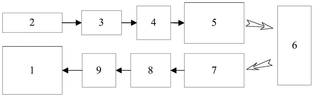
FIG. 1 is a schematic diagram of a biomimetic blocked ghost imaging system;
fig. 2 bionic speckle pattern (resolution 64 x 64);
FIG. 3 is a flow chart of a bionic block ghost imaging method;
FIG. 4 is a reconstructed image comparison (using a total variation reconstruction algorithm) of the bionic block ghost imaging and the traditional ghost imaging under the same sampling times;
fig. 5 shows the reconstruction efficiency comparison of the bionic block-ghost imaging with the conventional ghost imaging under the same PSNR (conventional ghost imaging time/bionic block-ghost imaging time).
Wherein: 1-an upper computer, 2-a light source, 3-a collimation optical system, 4-a diffraction optical element, 5-a spatial light modulator, 6-a target, 7-a receiving optical system, 8-an area array detector and 9-a collection card.
Detailed Description
The following describes embodiments of the present invention with reference to the drawings.
In the bionic blocking ghost imaging method disclosed in this embodiment, an applied system structure is shown in fig. 1, and the specific implementation steps are as follows:
initializing parameters for generating bionic speckles and parameters for ghost imaging sampling. Initializing parameters for generating the bionic speckles, and setting an image resolution of 64 multiplied by 64, a block number of 16, a maximum value of a bionic speckle discrete angle of 24, a maximum value of a bionic speckle discrete ring number of 4 and a bionic speckle inner ring radius of 19.7; and initializing ghost imaging sampling parameters, wherein the sampling ratio is 0.1, and the sampling times are 26.
And step two, generating a group of bionic speckles according to the bionic speckle parameters set in the step one, and obtaining higher imaging quality through sampling of the bionic speckles.
And (4) generating 26 bionic speckle patterns P according to the bionic speckle parameters set in the step one, and loading the patterns P to a Digital Micromirror Device (DMD), wherein the bionic speckle calculation formula is shown as a formula (6).
Figure BDA0002550923740000041
Wherein: r iskRepresents the radius of the kth ring of speckle, (1+ sin (π/Q))/(1-sin (π/Q)) represents the augmentation factor ε, θqIs the degree of the q sector. The bionic speckle P is an image with a resolution of 64 × 64, as shown in fig. 2.
And thirdly, partitioning the bionic speckles, and adopting speckles with lower resolution to reduce the sampling times of ghost imaging.
Performing 16 equal divisions on the bionic speckle P to obtain P1、p2、…、p16Each of piIs a 16 x 16 matrix.
Figure BDA0002550923740000051
After splitting 26 bionic speckles, pi={pi1,pi2,…,pi26}(i=1,2,…,16)。
And step four, sampling the target 6 by adopting the block bionic speckles in the step three to obtain a measured value of each block.
The light source 2 is collimated and split by a collimating lens and a DOE (diffractive optical element 4), the split light is projected to a DMD micro mirror surface to be modulated, and the modulated light is irradiated to a target 6O to be imaged to be sampled.
The array light irradiates on the object 6O to be imaged, and the CCD detector obtains a detection value y according to the formula (8)1、y2、…y16,yiIs the measured value y of the block sample number i corresponding to 26 timesi={yi1,yi2,…,yi26}(i=1,2,…,16)。
yi=∫∫pi(x,y)×oi(x,y)dxdy,(i=1,2...,16) (8)
And fifthly, reconstructing the image according to the blocked bionic speckles in the third step and the measured values in the fourth step.
piAnd yiCalculating the speckle with the number i and the measured value with the corresponding number by adopting a TV (total variation) reconstruction algorithm to obtain a reconstructed image oi',oi' is an image with a resolution of 16 × 16.
And step six, splicing the reconstructed block images obtained in the step five to obtain a whole reconstructed image, namely realizing the bionic block ghost imaging which takes both the imaging efficiency and the imaging quality into consideration.
According to the mode of selecting and splitting speckles in the third step, the method is implementedi' performing image stitching to obtain the whole reconstructed image O ', O ' is an image with the resolution of 64 × 64. The speckle splitting mode is first row and second row or first row and second row. The resulting reconstructed image O' is shown in fig. 4.
Figure BDA0002550923740000052
The system comprises a laser light source 2, a collimating optical system 3, a DOE, a DMD, a receiving optical system 7 and a CCD detector.
The laser light source 2, the collimating optical system 3, the DOE and the DMD are sequentially positioned on the same light path; the laser light source 2, the collimating optical system 3 and the DOE are used for generating area array light irradiating the DMD; the laser light source 2, the collimating optical system 3, the DOE and the DMD are used for generating speckles carrying known light field distribution information and projecting the speckles onto a target 6 to be imaged; the receiving optical system 7 and the CCD detector complete the collection of the total light intensity of the reflected light of the target 6. The computer carries out reconstruction operation and block image splicing operation on the bionic speckle information and the information acquired by the array detector 8.
The working method of the bionic blocking ghost imaging system disclosed by the embodiment comprises the following steps: the light source 2 emits a beam of light, the beam of light is split by the collimating optical system 3 and the beam splitter and then is irradiated to the surface of the spatial light modulator 5, the spatial light modulator 5 reflects the beam to the target 6 according to the bionic speckle reflected beam generated by the calculation in the step two, the reflected beam of the target 6 passes through the receiving optical system 7 to the area array detector 8 according to the step four, and the total light intensity of the reflected light of the target 6 is received by the area array detector 8. After repeated measurement, cross-correlation operation is carried out on the bionic speckle information and the light intensity information collected by the area array detector 8 according to the fifth step to obtain a reconstructed image of the target 6 blocks, and the block images reconstructed according to the sixth step are spliced to obtain a whole reconstructed image, namely the bionic blocked ghost imaging which gives consideration to both imaging efficiency and imaging quality is realized.
The above detailed description is intended to illustrate the objects, aspects and advantages of the present invention, and it should be understood that the above detailed description is only exemplary of the present invention and is not intended to limit the scope of the present invention, and any modifications, equivalents, improvements and the like made within the spirit and principle of the present invention should be included in the scope of the present invention.

Claims (2)

1.一种仿生分块鬼成像方法,其特征在于:包括如下步骤,1. a bionic block ghost imaging method, is characterized in that: comprise the steps, 步骤一、初始化用于产生仿生散斑的参数和鬼成像采样的参数;Step 1: Initialize parameters for generating bionic speckle and parameters for ghost imaging sampling; 步骤二、根据步骤一设定的仿生散斑参数生成一组仿生散斑,通过仿生散斑采样获得更高的成像质量;Step 2, generating a set of bionic speckles according to the bionic speckle parameters set in step 1, and obtaining higher imaging quality through bionic speckle sampling; 步骤三、通过对仿生散斑分块,采用更低分辨率的散斑能够降低鬼成像的采样次数;Step 3: By dividing the bionic speckle into blocks, using a lower resolution speckle can reduce the sampling times of ghost imaging; 步骤四、采用步骤三的分块仿生散斑对目标采样,得到每个分块的测量值;Step 4. Use the block bionic speckle of step 3 to sample the target, and obtain the measurement value of each block; 步骤五、根据步骤三的分块仿生散斑和步骤四的测量值,进行图像重构;Step 5: Perform image reconstruction according to the block bionic speckle of Step 3 and the measurement value of Step 4; 步骤六、对步骤五的重构后的分块图像拼接,得到整幅重构图像,即实现兼顾成像效率和成像质量的仿生分块鬼成像;Step 6, stitching the reconstructed segmented images in step 5 to obtain the entire reconstructed image, that is, to achieve bionic segmented ghost imaging that takes into account both imaging efficiency and imaging quality; 步骤一实现方法为,The implementation method of step 1 is: 步骤1.1:初始化产生仿生散斑的参数;Step 1.1: Initialize the parameters for generating bionic speckle; 设置图像分辨率X×X、分块数N、仿生散斑离散角度最大值Q、仿生散斑离散环数最大值K、以及仿生散斑内环半径r0;所述的分块数N为平方数;Set the image resolution X×X, the number of blocks N, the maximum value Q of the bionic speckle discrete angle, the maximum value K of the number of bionic speckle discrete rings, and the radius r 0 of the bionic speckle inner ring; the number of blocks N is the square of; 步骤1.2:初始化鬼成像采样参数;Step 1.2: Initialize ghost imaging sampling parameters; 设置采样比为a,采样次数为A=X×X×a/N,A四舍五入取整;Set the sampling ratio to a, the sampling times to be A=X×X×a/N, and A is rounded to the nearest integer; 步骤二实现方法为,The implementation method of step 2 is: 根据步骤一设定的仿生散斑参数,生成A张仿生散斑P,仿生散斑计算公式如式所示;According to the bionic speckle parameters set in step 1, A sheets of bionic speckle P are generated, and the calculation formula of bionic speckle is shown in the formula;
Figure FDA0003557501490000011
其中:rk代表散斑第k环的半径,(1+sin(π/Q))/(1-sin(π/Q))代表增大系数ε,θq是q扇区的度数;仿生散斑P是分辨率为X×X的图像;Where: r k represents the radius of the kth ring of the speckle, (1+sin(π/Q))/(1-sin(π/Q)) represents the increase coefficient ε, θ q is the degree of the q sector; bionic Speckle P is an image of resolution X×X; 步骤三实现方法为,The implementation method of step 3 is: 对仿生散斑P进行N等分,得到p1、p2、…、pN,每个pi
Figure FDA0003557501490000012
的矩阵;此处采用先行后列或者先列后行的方式对其进行拆分并编号,其中p1为1号散斑,pN为N号散斑;
Divide the bionic speckle P into N equal parts to obtain p 1 , p 2 , ..., p N , each p i is
Figure FDA0003557501490000012
The matrix of ; here is split and numbered in the manner of row first, column first or row first, where p 1 is the speckle No. 1, and p N is the speckle No. N;
Figure FDA0003557501490000021
在拆分完A个仿生散斑后,pi={pi1,pi2,...,piA}(i=1,2,…,N);After splitting A bionic speckles, p i ={p i1 ,p i2 ,...,p iA }(i=1,2,...,N); 步骤四实现方法为,The implementation method of step 4 is: 将仿生散斑投射到待成像目标O进行采样,目标O与仿生散斑采取同样的方式区分为o1、o2、…oNProject the bionic speckle to the target O to be imaged for sampling, and the target O and the bionic speckle are divided into o 1 , o 2 , ... o N in the same way; 光源投射在待成像目标O上,探测器根据式得到测量值y1、y2、…yN,yi是编号为i所对应分块采样A次的测量值,yi={yi1,yi2,...,yiA}(i=1,2,…,N);The light source is projected on the target O to be imaged , and the detector obtains the measured values y 1 , y 2 , . y i2 ,...,y iA }(i=1,2,...,N); yi=∫∫pi(x,y)×oi(x,y)dxdy,(i=1,2...,N) (3)y i =∫∫pi (x,y)×o i ( x,y)dxdy,(i=1,2...,N) (3) 步骤五实现方法为,The implementation method of step 5 is: pi与yi为编号为i的散斑与其对应编号的测量值,采用重构算法对其进行计算得到重构图像oi',计算公式如式所示,oi'是分辨率为
Figure FDA0003557501490000022
图像;
p i and y i are the measured values of the speckle numbered i and its corresponding number, and the reconstruction algorithm is used to calculate it to obtain the reconstructed image o i ', the calculation formula is shown in the formula, o i ' is the resolution of
Figure FDA0003557501490000022
image;
Figure FDA0003557501490000023
步骤六实现方法为,The implementation method of step 6 is: 按照步骤三中选用拆分散斑的方式,将oi'进行图像拼接得到整幅重构图像O',O'是分辨率为X×X的图像;所述拆分散斑的方式为先行后列或先列后行;According to the method of splitting the speckles in step 3, o i ' is stitched to obtain the entire reconstructed image O', and O' is an image with a resolution of X × X; the method of splitting the speckles is to first row and then column or row before row;
Figure FDA0003557501490000024
.
2.一种仿生分块鬼成像系统,用于实现如权利要求1所述的一种仿生分块鬼成像方法,其特征在于:包括光源(2)、准直光学系统(3)、分光器、空间光调制器(5)、接收光学系统(7)、面阵探测器(8);2. A bionic segmented ghost imaging system for realizing a bionic segmented ghost imaging method as claimed in claim 1, characterized in that: comprising a light source (2), a collimating optical system (3), a beam splitter , a spatial light modulator (5), a receiving optical system (7), an area array detector (8); 光源(2)、准直光学系统(3)、分光器、空间光调制器(5)按顺序依次位于同一光路上;光源(2)、准直光学系统(3)和分光器用于产生照射到空间光调制器(5)的面阵光;光源(2)、准直光学系统(3)、分光器和空间光调制器(5)用于产生携带已知光场分布信息的散斑投射到待成像的目标(6)上;接收光学系统(7)和面阵探测器(8)完成目标(6)反射光总光强的采集;相关运算器将仿生散斑信息和面阵探测器(8)采集的信息进行重构运算以及分块图像拼接运算;The light source (2), the collimating optical system (3), the beam splitter, and the spatial light modulator (5) are located on the same optical path in sequence; the light source (2), the collimating optical system (3) and the beam splitter are used for The area array light of the spatial light modulator (5); the light source (2), the collimating optical system (3), the beam splitter and the spatial light modulator (5) are used to generate the speckle carrying the known light field distribution information and project onto the light source. on the target to be imaged (6); the receiving optical system (7) and the area array detector (8) complete the collection of the total light intensity of the reflected light of the target (6); the correlation operator combines the bionic speckle information with the area array detector ( 8) Reconstruction operation and block image splicing operation are performed on the collected information; 光源(2)发出一束光,经过准直光学系统(3)和分光器分束后照射至空间光调制器(5)表面,空间光调制器(5)根据步骤二计算生成的仿生散斑反射光束至目标(6),目标(6)反射光束根据步骤四通过接收光学系统(7)到面阵探测器(8),目标(6)反射光的总光强被面阵探测器(8)接收;在重复多次测量后,根据步骤五对仿生散斑信息和面阵探测器(8)采集的光强信息进行互相关运算后即得到目标(6)分块的重构图像,按照步骤六对步骤五重构后的分块图像拼接,得到整幅重构图像,即实现兼顾成像效率和成像质量的仿生分块鬼成像。The light source (2) emits a beam of light, which is split by the collimating optical system (3) and the beam splitter and then irradiated to the surface of the spatial light modulator (5), and the spatial light modulator (5) calculates and generates the bionic speckle according to step 2 The reflected beam is reflected to the target (6), and the reflected beam of the target (6) passes through the receiving optical system (7) to the area array detector (8) according to step 4, and the total light intensity of the reflected light from the target (6) is detected by the area array detector (8). ) to receive; after repeating the measurement for many times, according to step 5, the cross-correlation operation is performed on the bionic speckle information and the light intensity information collected by the area array detector (8) to obtain the reconstructed image of the target (6) blocks, according to In step 6, the segmented images reconstructed in step 5 are stitched together to obtain the entire reconstructed image, that is, to achieve bionic segmented ghost imaging that takes both imaging efficiency and imaging quality into consideration.
CN202010575766.8A 2020-06-22 2020-06-22 Bionic blocking ghost imaging method and system Active CN111551955B (en)

Priority Applications (2)

Application Number Priority Date Filing Date Title
CN202010575766.8A CN111551955B (en) 2020-06-22 2020-06-22 Bionic blocking ghost imaging method and system
AU2021101688A AU2021101688A4 (en) 2020-06-22 2021-04-01 Method and system of parallel retina-like ghost imaging

Applications Claiming Priority (1)

Application Number Priority Date Filing Date Title
CN202010575766.8A CN111551955B (en) 2020-06-22 2020-06-22 Bionic blocking ghost imaging method and system

Publications (2)

Publication Number Publication Date
CN111551955A CN111551955A (en) 2020-08-18
CN111551955B true CN111551955B (en) 2022-07-08

Family

ID=71999583

Family Applications (1)

Application Number Title Priority Date Filing Date
CN202010575766.8A Active CN111551955B (en) 2020-06-22 2020-06-22 Bionic blocking ghost imaging method and system

Country Status (2)

Country Link
CN (1) CN111551955B (en)
AU (1) AU2021101688A4 (en)

Families Citing this family (3)

* Cited by examiner, † Cited by third party
Publication number Priority date Publication date Assignee Title
CN113219490B (en) * 2021-05-14 2023-12-29 合肥工业大学 Reflective scanning calculation polarization ghost imaging system under haze disperse system
CN113240610B (en) * 2021-05-27 2023-05-12 清华大学深圳国际研究生院 Double-channel ghost imaging reconstruction method and system based on human eye imitation mechanism
CN113284071B (en) * 2021-06-15 2022-10-18 北京理工大学 Periopsis imaging method and system based on human retina mechanism simulation

Family Cites Families (9)

* Cited by examiner, † Cited by third party
Publication number Priority date Publication date Assignee Title
US8334893B2 (en) * 2008-11-07 2012-12-18 Honeywell International Inc. Method and apparatus for combining range information with an optical image
CN104933745B (en) * 2015-06-26 2018-09-04 南京理工大学 The relevance imaging method of raising image resolution ratio based on fractal interpolation
GB2541675B (en) * 2015-08-25 2021-12-15 Bae Systems Plc Imaging apparatus and method
CN105388486A (en) * 2015-12-15 2016-03-09 西安电子科技大学 Ghost imaging system and imaging method based on fiber array pseudo-thermal light
CN107016637B (en) * 2017-03-21 2019-09-17 北京理工大学 It is a kind of for improving the self adaptive imaging method of terrible imaging efficiency
CN107462932B (en) * 2017-08-04 2020-03-17 西安交通大学 Visual calculation ghost imaging system and imaging method based on optical calculation
US11425359B2 (en) * 2018-08-23 2022-08-23 Lg Electronics Inc. Apparatus and method for generating three-dimensional image
CN110136187B (en) * 2019-05-17 2021-09-24 北京邮电大学 A method for reducing the computational cost of correlated imaging based on compressive sensing observation matrix segmentation
CN110807779A (en) * 2019-10-12 2020-02-18 湖北工业大学 A Compressed Computational Ghost Imaging Method and System Based on Region Segmentation

Also Published As

Publication number Publication date
CN111551955A (en) 2020-08-18
AU2021101688A4 (en) 2021-05-20

Similar Documents

Publication Publication Date Title
Musarra et al. Non-line-of-sight three-dimensional imaging with a single-pixel camera
CN111551955B (en) Bionic blocking ghost imaging method and system
CN103363924B (en) A kind of three-dimensional computations ghost imaging system of compression and method
CN104121990B (en) Compressed sensing broadband Hyperspectral imager based on random grating
US20180224552A1 (en) Compressed-sensing ultrafast photography (cup)
JP2017507585A (en) Imaging system and method using pinhole array
WO2009108050A9 (en) Image reconstructor
CN103940370B (en) Target object 3 D information obtaining method based on cycle relatively prime hybrid coding
CN113574438B (en) Systems and methods for imaging through scattering media
CN107421640B (en) Multispectral light field imaging system and method based on the principle of chromatic aberration amplification
CN106204732A (en) The three-dimensional rebuilding method of dynamic exposure and system
JP2011182237A (en) Compound-eye imaging device, and image processing method in the same
CN113790676B (en) A three-dimensional spatial spectral imaging method and device based on coded aperture and light field distribution
Zhao et al. Three-dimensional imaging interferometric synthetic aperture ladar
CN105303572B (en) Based on the main depth information acquisition method passively combined
CN113218914A (en) Non-invasive scattering medium particle spread function obtaining device and method
CN113554744A (en) A three-dimensional imaging method and device for fast scanning of large-volume scattering samples
Zhang et al. Quantum light-field microscopy for volumetric imaging with extreme depth of field
AU2020408599A1 (en) Light field reconstruction method and system using depth sampling
CN104849769B (en) A system and method for three-dimensional ranging imaging
CN113284071B (en) Periopsis imaging method and system based on human retina mechanism simulation
CN1959341A (en) Optical imaging distance measuring device for single-aperture multiple imaging
Yang et al. Single-pixel edge imaging with gradient Radon spectrum
US20240428375A1 (en) Holographic ultra resolution imaging
CN113936126A (en) Image reconstruction method and image reconstruction device based on single-pixel imaging

Legal Events

Date Code Title Description
PB01 Publication
PB01 Publication
SE01 Entry into force of request for substantive examination
GR01 Patent grant
GR01 Patent grant