Urban pipe network measuring device and measuring method thereof
Technical Field
The invention relates to the technical field of underground pipeline measurement, in particular to a city pipe network measuring device and a measuring method thereof.
Background
Along with the depth of the urbanization process, the scale of the urban underground pipe network is continuously enlarged, but the laying time of a large number of pipelines is long, so that the pipelines reach or approach the service life at present, and even a plurality of pipelines fail to reach the service life and are subjected to accidents due to aging. The classification of the pipeline detection defects can be divided into two types, one type is structural defects, and the structural defects comprise 9 types, such as fracture, deformation, dislocation, disjunction, leakage, corrosion, rubber ring falling, branch pipe concealed connection, foreign matter invasion and the like; one category is functional defects including 7 types of deposits, scale, obstructions, roots, depressions, dams, and scum.
In order to avoid loss caused by aging and damage of the pipe network, the pipe network needs to be measured to obtain the health state of the pipe network. In the measuring process, the inspection well can directly expose the pipe network, and the inspection well is usually arranged at an important place such as an inflection point of the pipe network, so that the measurement by using the inspection well is a very effective means. In the prior art, the inner pipe network of the inspection well is measured mainly by a manual mode, the efficiency is low, and the measured data can be used only by frequently converting the measured data because the position of the device is constantly changed when an automatic device is used for measuring, so that the complexity is high.
Disclosure of Invention
The urban pipe network measuring device and the urban pipe network measuring method provided by the invention have the advantages of low measuring complexity and high efficiency.
In order to achieve the purpose, the invention adopts the specific scheme that:
a city pipe network measuring device comprises a shell, wherein a storage box is fixedly arranged at the top of the shell, a control box is arranged in the storage box, two supporting mechanisms for fixing the shell above an inspection well are fixedly connected to the side part of the shell, the two supporting mechanisms are symmetrically arranged, an upper supporting plate and a lower supporting plate are fixedly arranged in the shell, a first motor is fixedly arranged on the upper supporting plate, a steel rope is wound on an output shaft of the first motor, a heavy hammer is fixedly connected after the steel rope downwards penetrates through the upper supporting plate and the lower supporting plate, a plurality of first measuring elements uniformly distributed in the circumferential direction are fixedly arranged on the heavy hammer, a second motor is fixedly connected to the lower end of the heavy hammer, a second measuring element is fixedly arranged on an output shaft of the second motor, and a frame body is fixedly arranged on the lower surface of the lower supporting plate, a sponge protective layer is arranged in the frame body, a containing cavity is formed in the middle of the sponge protective layer, and a through hole is formed in the bottom of the shell; the first motor, the second motor, the first measuring element and the second measuring element are all electrically connected with the control box.
Preferably, the supporting mechanism includes a channel steel fixedly connected to the housing, two side walls of the lower end of the channel steel are respectively provided with a first square positioning hole, the channel steel is detachably provided with a supporting rod, the supporting rod is provided with a second square positioning hole corresponding to the first square positioning hole, and positioning rods penetrate through the first square positioning hole and the second square positioning hole.
Preferably, a plurality of inserting plates are movably arranged in the accommodating box, a plurality of slots which are uniformly distributed along the length direction are formed in the supporting rod, and when the inserting plates are inserted into the slots, one part of the inserting plates extends out of the slots.
Preferably, the slot includes first recess and the second recess that communicates with each other, first recess with the second recess link up respectively the side of two relative settings of bracing piece, the width of first recess is greater than the width of second recess, the picture peg includes first portion and the second part of an organic whole connection, the width of first portion is greater than the width of second recess and be less than the width of first recess, the width of second portion is less than the width of second recess.
Preferably, the middle part of the upper support plate is provided with an inverted cone-shaped guide hole, and the steel rope passes through the guide hole.
Preferably, the shell is internally and fixedly provided with a support, the support is positioned between the upper supporting plate and the lower supporting plate, and the support is fixedly provided with a stable detection mechanism for detecting the stability of the steel rope.
Preferably, steady detection mechanism is including fixed setting up square pipe on the support, the inside of square pipe is fixed and is provided with four pressure sensor, and four pressure sensor is located respectively on four lateral walls of square pipe, the steel cable is followed square intraductal the passing.
Preferably, the bottom of the housing is provided with a plurality of road wheels.
Preferably, a motor support is fixedly arranged on the upper support plate, and the first motor is fixedly arranged on the motor support.
The invention also provides a measuring method of the urban pipe network measuring device, which comprises the following steps:
s1, selecting a manhole and removing the manhole cover;
s2, fixing the outer shell above the inspection well by using the supporting mechanism, and aligning the outer shell with the axis of the inspection well;
s3, the control box is used for controlling the first motor to release the steel rope, and the heavy hammer drives the first measuring element, the second motor and the second measuring element to move downwards into the inspection well;
s4, measuring a pipe network in the inspection well by using the first measuring element and the second measuring element, and sending measurement data to the control box;
s5, controlling the first motor to wind the steel rope on the output shaft of the first motor by using the control box, and driving the heavy hammer, the first measuring element and the second measuring element to move upwards into the cavity.
When the device is used for measurement, the position of the device is fixed, the measurement result can be taken as absolute reference by taking the position of the device, complex data conversion is not needed, the complexity is low, automatic measurement can be realized, and the measurement efficiency is greatly improved.
Drawings
In order to more clearly illustrate the embodiments of the present invention or the technical solutions in the prior art, the drawings used in the description of the embodiments or the prior art will be briefly described below, it is obvious that the drawings in the following description are only some embodiments of the present invention, and for those skilled in the art, other drawings can be obtained according to the drawings without creative efforts.
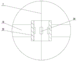
Fig. 1 is a schematic view of the overall structure of the embodiment of the present invention.
Fig. 2 is a schematic diagram of a plateau detecting mechanism.
Fig. 3 is a schematic view of the support mechanism.
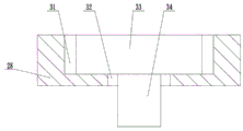
Fig. 4 is a schematic view of the mating of the board and the socket.
Reference numerals: 1-storage box, 2-plug board, 3-control box, 4-shell, 5-first motor, 6-motor support, 7-steel rope, 8-upper support board, 9-guide hole, 10-support, 11-smooth detection mechanism, 12-lower support board, 13-frame, 14-sponge protective layer, 15-cavity, 16-first measurement element, 17-second measurement element, 18-second motor, 19-weight, 20-walking wheel, 21-through hole, 22-support mechanism, 23-square tube, 24-pressure sensor, 25-channel steel, 26-first square positioning hole, 27-positioning rod, 28-support rod, 29-second square positioning hole, 30-slot, 31-first groove, 32-second recess, 33-first portion, 34-second portion.
Detailed Description
The technical solutions in the embodiments of the present invention will be clearly and completely described below with reference to the drawings in the embodiments of the present invention, and it is obvious that the described embodiments are only a part of the embodiments of the present invention, and not all of the embodiments. All other embodiments, which can be derived by a person skilled in the art from the embodiments given herein without making any creative effort, shall fall within the protection scope of the present invention.
Referring to fig. 1 to 4, fig. 1 is a schematic view of an overall structure of an embodiment of the present invention, fig. 2 is a schematic view of a smooth detection mechanism, fig. 3 is a schematic view of a support mechanism, and fig. 4 is a schematic view of a matching manner of a board and a slot.
A city pipe network measuring device comprises a shell 4, a storage box 1 is fixedly arranged at the top of the shell 4, a control box 3 is arranged in the storage box 1, two supporting mechanisms 22 for fixing the shell 4 above an inspection well are fixedly connected to the side portion of the shell 4, the two supporting mechanisms 22 are symmetrically arranged, an upper supporting plate 8 and a lower supporting plate 12 are fixedly arranged in the shell 4, a first motor 5 is fixedly arranged on the upper supporting plate 8, a steel rope 7 is wound on an output shaft of the first motor 5, a heavy hammer 19 is fixedly connected after the steel rope 7 downwards penetrates through the upper supporting plate 8 and the lower supporting plate 12, a plurality of first measuring elements 16 uniformly distributed along the circumferential direction are fixedly arranged on the heavy hammer 19, a second motor 18 is fixedly connected to the lower end of the heavy hammer 19, a second measuring element 17 is fixedly arranged on an output shaft of the second motor 18, and a frame body 13 is fixedly arranged on the lower surface of the lower supporting plate 12, a sponge protective layer 14 is arranged in the frame body 13, a cavity 15 is arranged in the middle of the sponge protective layer 14, and a through hole 21 is arranged at the bottom of the shell 4. The first motor 5, the second motor 18, the first measuring element 16 and the second measuring element 17 are all electrically connected with the control box 3.
When the device is used, firstly, the device is integrally moved to a manhole, then a manhole cover is opened, the device is arranged above the manhole by using the supporting mechanism 22, then the steel rope 7 is put down by using the first motor 5, the weight 19 ensures that the steel rope 7 can be in a tight state, so that the stability of the first measuring element 16 and the second measuring element 17 is improved, after the first measuring element 16 and the second measuring element 17 downwards enter the manhole, a city pipe network in the manhole can be measured, the first measuring element 16 is provided with a plurality of measuring elements, and the second measuring element 17 can be driven to rotate by the second motor 18, so that the first measuring element 16 and the second measuring element 17 can perform comprehensive measurement, the richness and accuracy of measurement results are ensured, and according to actual use requirements, the first measuring element 16 and the second measuring element 17 can be selected to be different types of elements, for example, the first measuring element 16 may be selected as a camera, the second measuring element 17 may be selected as an infrared distance sensor, etc. In view of the complex environment in the inspection well, in order to ensure that the first measuring element 16 and the second measuring element 17 can move down smoothly for measurement, the position between the device and the axis of the inspection well can be changed so that there is no obstacle under the weight 19. After the measurement is finished, the weight 19 is lifted up and down by the first motor 5, and finally the first measuring element 16 and the second measuring element 17 enter the sponge protective layer 14 for protection, so that the first measuring element 17 and the second measuring element 17 are prevented from being damaged in the moving process.
In this embodiment, the specific structure of the supporting mechanism 22 is: the supporting mechanism 22 includes a channel steel 25 fixedly connected to the housing 4, two side walls of a lower end of the channel steel 25 are respectively provided with a first square positioning hole 26, a supporting rod 28 is detachably disposed in the channel steel 25, the supporting rod 28 is provided with a second square positioning hole 29 corresponding to the first square positioning hole 26, and a positioning rod 27 is inserted into the first square positioning hole 26 and the second square positioning hole 29. When not in use, accomodate the bracing piece 28 in the channel-section steel 25, then utilize locating lever 27 to pass first square locating hole 26 and second square locating hole 29 to fix the position of bracing piece 28, avoid bracing piece 28 to drop at the in-process that removes. When the device is used, the positioning rod 27 is firstly pulled out, then the supporting rods 28 are adjusted to horizontally extend, and then the positioning rod 27 penetrates through the first square positioning hole 26 and the second square positioning hole 29 again, so that the position of the positioning rod 27 is kept in a horizontal state, and the two supporting rods 28 respectively extend to the outside of the inspection well, so that the device can be fixed above the inspection well. In other embodiments of the present invention, the cross-sectional shapes of the positioning holes and the positioning rods 27 may be adjusted as long as the support rods 28 can be fixed in the vertical direction and the horizontal direction, such as an oval shape, a star shape, or a diamond shape.
In this embodiment, in order to avoid the accuracy of the measurement result from the movement of the device during the use process, a plurality of insertion plates 2 are movably disposed in the storage box 1, a plurality of slots 30 are disposed on the support rod 28, the slots 30 are uniformly distributed along the length direction, and when the insertion plates 2 are inserted into the slots 30, a part of the insertion plates 2 extends out of the slots 30. After the device is arranged, the inserting plate 2 is inserted into the slot 30, because a part of the inserting plate 2 extends out of the slot 30, the part can extend into the inspection well, and the proper slot 30 can be selected to enable the inserting plate 2 to be abutted against the inner wall of the inspection well after the inserting plate extends out of the slot 30, so that the inserting plate 2 can be used for preventing the device from moving in the extending direction of the supporting rod 28. In other embodiments of the present invention, the number of the supporting mechanisms 22 may be increased, for example, four supporting mechanisms 22 are provided, and the four supporting mechanisms 22 are distributed in a cross shape, so as to ensure that the device does not have any lateral deviation.
In the present embodiment, the slot 30 includes a first groove 31 and a second groove 32 that are communicated with each other, the first groove 31 and the second groove 32 respectively penetrate two opposite side surfaces of the supporting rod 28, the width of the first groove 31 is greater than the width of the second groove 32, the inserting plate 2 includes a first portion 33 and a second portion 34 that are integrally connected, the width of the first portion 33 is greater than the width of the second groove 32 and smaller than the width of the first groove 31, and the width of the second portion 34 is smaller than the width of the second groove 32. By adopting the inserting plate 2 and the inserting groove 30, the inserting plate 2 can be directly inserted into the inserting groove 30 without other operations, and the operation is convenient and quick.
In this embodiment, the middle of the upper support plate 8 is opened with a guide hole 9 having an inverted cone shape, and the steel cable 7 passes through the guide hole 9. The guide holes 9 are used for limiting the direction of the steel cables 7, ensuring that the steel cables 7 can be in a state of being vertical to the lower support plate 12 after entering between the upper support plate 8 and the lower support plate 12, and being beneficial to determining the positions of the first measuring element 16 and the second measuring element 17. Set up guiding hole 9 to the toper in order to increase the area of contact of steel cable 7 and guiding hole 9 inner wall when ground has certain gradient, because steel cable 7 can keep absolute perpendicular state under the effect of weight 19 this moment, and go up backup pad 8 and the parallel tilt state of ground, so steel cable 7 can contact with the inner wall of guiding hole 9, can avoid fish tail steel cable 7 after long-time the use through increasing area of contact, and then extension means's life.
In this embodiment, a bracket 10 is fixedly disposed inside the housing 4, the bracket 10 is located between the upper support plate 8 and the lower support plate 12, and a stability detection mechanism 11 for detecting the stability of the steel cable 7 is fixedly disposed on the bracket 10. The weight 19 is easy to shake during descending, and if measurement is performed during shaking, the accuracy of the measurement result is inevitably reduced, so measurement needs to be performed after the weight 19 is stable, but the weight 19 is constantly moving and difficult to directly detect, and the stability of the weight 19 is synchronous with the steel rope 7, so that the steel rope 7 can be detected by the stability detection mechanism 11, and the stability of the weight 19 can be obtained.
In this embodiment, the smoothness detection mechanism 11 includes a square tube 23 fixedly disposed on the support 10, four pressure sensors 24 are fixedly disposed inside the square tube 23, the four pressure sensors 24 are respectively disposed on four side walls of the square tube 23, and the steel cable 7 passes through the square tube 23. The specific detection principle is as follows: if the weight 19 is not stable enough, the steel rope 7 will intermittently trigger one or more pressure sensors 24, if the weight 19 is stable, only one or none of the pressure sensors 24 will be triggered, the detection is far from simple, the feasibility is high, and the cost is low.
In the present embodiment, a plurality of traveling wheels 20 are provided at the bottom of the housing 4. The road wheels 20 are used to conveniently move the device.
In this embodiment, the upper support plate 8 is fixedly provided with a motor support 6, and the first motor 5 is fixedly arranged on the motor support 6.
A measuring method of a city pipe network measuring device comprises steps S1 to S5.
S1, selecting the inspection well and removing the inspection well cover.
S2, the housing 4 is fixed above the inspection well by the support mechanism 22, and the housing 4 is aligned with the axis of the inspection well.
S3, the control box 3 is used for controlling the first motor 5 to release the steel rope 7, and the weight 19 drives the first measuring element 16, the second motor 18 and the second measuring element 17 to move downwards into the inspection well.
S4, the first measuring element 16 and the second measuring element 17 are used for measuring the pipe network in the inspection well, and the measured data are sent to the control box 3.
S5, the control box 3 controls the first motor 5 to wind the steel cable 7 around the output shaft of the first motor 5, and drives the weight 19, the first measuring element 16 and the second measuring element 17 to move upward into the cavity 15.
By adopting the method, the urban pipe network in the inspection well can be rapidly and accurately measured.
The embodiments in the present description are described in a progressive manner, each embodiment focuses on differences from other embodiments, and the same and similar parts among the embodiments are referred to each other.
The previous description of the disclosed embodiments is provided to enable any person skilled in the art to make or use the present invention. Various modifications to these embodiments will be readily apparent to those skilled in the art, and the generic principles defined herein may be applied to other embodiments without departing from the spirit or scope of the invention. Thus, the present invention is not intended to be limited to the embodiments shown herein but is to be accorded the widest scope consistent with the principles and novel features disclosed herein.