CN111634603B - Device for transferring automobile camshaft and camshaft cover on production line - Google Patents
Device for transferring automobile camshaft and camshaft cover on production line Download PDFInfo
- Publication number
- CN111634603B CN111634603B CN202010464796.1A CN202010464796A CN111634603B CN 111634603 B CN111634603 B CN 111634603B CN 202010464796 A CN202010464796 A CN 202010464796A CN 111634603 B CN111634603 B CN 111634603B
- Authority
- CN
- China
- Prior art keywords
- camshaft
- cam shaft
- chain
- support
- base
- Prior art date
- Legal status (The legal status is an assumption and is not a legal conclusion. Google has not performed a legal analysis and makes no representation as to the accuracy of the status listed.)
- Active
Links
Images


Classifications
-
- B—PERFORMING OPERATIONS; TRANSPORTING
- B65—CONVEYING; PACKING; STORING; HANDLING THIN OR FILAMENTARY MATERIAL
- B65G—TRANSPORT OR STORAGE DEVICES, e.g. CONVEYORS FOR LOADING OR TIPPING, SHOP CONVEYOR SYSTEMS OR PNEUMATIC TUBE CONVEYORS
- B65G7/00—Devices for assisting manual moving or tilting heavy loads
- B65G7/02—Devices adapted to be interposed between loads and the ground or floor, e.g. crowbars with means for assisting conveyance of loads
Landscapes
- Automatic Assembly (AREA)
- Automobile Manufacture Line, Endless Track Vehicle, Trailer (AREA)
Abstract
The invention discloses a device for transferring an automobile camshaft and a camshaft cover on a production line, relates to the field of automobile engine assembly, and solves the problem that in the prior art, a single transfer efficiency of a camshaft and camshaft cover transfer device is low, and the technical key points are as follows: the cam shaft cover conveying device comprises a base, wherein a first cam shaft support and a second cam shaft support are arranged on the base, a cam shaft cover hung in the base is conveyed to the outside of the base when the cam shaft cover support rotates, and the first cam shaft support, the second cam shaft support and the cam shaft cover support are driven to synchronously rotate by a driving unit arranged in the base; the invention improves the transferring quantity, is convenient for workers to take the camshaft and the camshaft cover, and can effectively prevent the workers from neglecting to load the camshaft or the camshaft cover.
Description
Technical Field
The invention relates to the field of automobile engine assembly, in particular to a device for transferring an automobile camshaft and a camshaft cover on a production line.
Background
Cylinder cap camshaft, cup tappet, camshaft cover among the automobile engine all assemble at the cylinder cap, transport to the final assembly workshop section through proper motion dolly after the assembly is accomplished and continue the assembly, because the cylinder cap bolt interferes with the camshaft in the installation, need loosen the camshaft cover bolt soon, dismantle camshaft cover and camshaft, screw up the cylinder cap bolt, then secondary assembly camshaft and camshaft cover.
Chinese patent publication No. CN205837436U discloses a device for transferring camshafts and camshaft covers on a production line, which comprises a positioning bottom plate, a pair of intake camshaft supports and a pair of exhaust camshaft supports detachably fixed on the positioning bottom plate; a first camshaft cover positioning groove, a second camshaft cover positioning groove and a shaft cover positioning groove are sequentially formed in the positioning bottom plate from left to right, the shaft cover positioning groove comprises a left groove and a right groove which are communicated with each other, the left groove and the right groove are square grooves, the bottom edges of the left groove and the right groove are flush, and the top edge of the left groove is higher than the top edge of the right groove; positioning holes are formed in the joint parts of the bottom edges of the left groove and the right groove and between the first camshaft cover positioning groove and the second camshaft cover positioning groove; the positioning bottom plate is also provided with two rows of positioning pin holes which are respectively and symmetrically arranged at the upper side and the lower side of the shaft cover positioning groove; handles are fixed on the left side and the right side of the positioning bottom plate. The device can only transport a set of camshaft and camshaft cover once, transports inefficiency, consequently, we have provided a device that is used for car camshaft and camshaft cover to transport on the production line.
Disclosure of Invention
The invention aims to solve the technical problem of providing a device for transferring automobile camshafts and camshaft covers on a production line, and aims to solve the problem of low single transfer efficiency of camshaft and camshaft cover transfer devices in the prior art.
In order to achieve the purpose, the invention provides the following technical scheme:
the utility model provides a device that is used for car camshaft and camshaft cover to transport on production line, the on-line screen storage device comprises a base, be equipped with first camshaft support and the second camshaft support that is used for carrying intake camshaft and exhaust camshaft respectively on the base, be equipped with the first camshaft cover support that is used for carrying the camshaft cover between first camshaft support and the second camshaft support, when first camshaft support and second camshaft support rotate, will carry the outside of transporting the base at the inside camshaft of base, when first camshaft cover support rotates, will carry the outside of transporting the base at the inside camshaft cover of base, first camshaft support, second camshaft support and first camshaft cover support drive synchronous rotation through the drive unit who establishes in the base.
As a further proposal of the invention, the upper end of the base is provided with an upper supporting plate; the first cam shaft support comprises an upper movement assembly and a lower rotation assembly, the upper movement assembly is mounted on the upper supporting plate through a bearing, the lower rotation assembly is mounted on the base through a bearing, the upper movement assembly and the lower rotation assembly are connected through a connecting shaft, a first cam fixing unit is arranged on the base, a second cam fixing unit is arranged on the lower rotation assembly, and two ends of the cam shaft are respectively clamped on the first cam fixing unit and the second cam fixing unit.
As a further scheme of the invention, the upper movement assembly comprises two groups of chain wheels and chains, the chain wheels are fixed on the upper supporting plate through bearings, the chains are sleeved on the chain wheels, the structure of the lower rotation assembly is the same as that of the upper movement assembly, and two ends of the connecting shaft are fixed on the chain wheels of the upper movement assembly and the lower rotation assembly.
As a further scheme of the invention, the first cam fixing unit comprises a chain connecting block and a cam shaft bracket, the chain connecting block is a U-shaped block, a mounting hole matched with the chain is arranged on the chain connecting block, and the chain connecting block is mounted on a chain shaft of the chain; the cam shaft frame is provided with a circular groove for mounting a cam shaft, the circular groove is provided with an opening, the cam shaft frame with the angle smaller than the opening is also provided with an installation rod for installing the cam shaft frame on the chain connecting block, the installation rod is provided with a flange plate, and the cam shaft frame is fixed below the chain connecting block through a screw; the second cam fixing unit has the same structure as the first cam fixing unit.
As a further aspect of the present invention, the second camshaft support has the same structure as the first camshaft support.
As a further scheme of the present invention, the first camshaft cover bracket includes a third rotating assembly and a fourth rotating assembly, the structure of the third rotating assembly and the structure of the fourth rotating assembly are the same as the structure of the upper moving assembly, a second camshaft cover bracket is provided on the third rotating assembly and the fourth rotating assembly, the second camshaft cover bracket is a round bar, and a hook is provided on the second camshaft cover bracket.
As a further aspect of the invention, the outer side of the second wheel axle cover bracket is provided with a protective layer.
As a further aspect of the present invention, the driving unit includes a driving motor, the driving motor drives the first camshaft support, the second camshaft support and the first camshaft cover support to rotate through a driven sprocket and a duplex sprocket, the driving motor is connected with the duplex sprocket, the duplex sprocket is connected with the driven sprocket through a chain, the driven sprocket is fixedly connected to the chain shafts on the first camshaft support and the second camshaft support, and the duplex sprocket is fixedly connected to the chain shaft on the first camshaft cover support; the driving unit comprises a control device which controls the driving motor to rotate forwards and backwards.
In conclusion, compared with the prior art, the invention has the following beneficial effects:
the cam shaft and the cam shaft cover are conveyed by the station trolley, the single rotation amount is large, the brackets for mounting the air inlet cam shaft, the air outlet cam shaft and the cam shaft cover according to the number of the table sleeves are arranged, and the cam shaft cover are placed at positions easy to take by driving the brackets to move.
Drawings
Fig. 1 is a schematic structural diagram of a device for transferring automobile camshafts and camshaft covers on a production line.
Fig. 2 is a schematic structural diagram of a first rotating assembly in the device for transferring the automobile camshaft and the camshaft cover on the production line.
Fig. 3 is a schematic structural view of a chain connecting block in the apparatus for transferring the automobile camshaft and the camshaft cover on the production line.
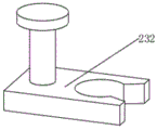
Fig. 4 is a schematic structural diagram of a camshaft bracket in the device for transferring the automobile camshaft and the camshaft cover on the production line.
Reference numerals: 100-base, 110-upper support plate, 200-first camshaft support, 210-upper motion assembly, 211-sprocket, 212-chain, 231-chain connecting block, 232-camshaft support, 220-lower rotation assembly, 230-first cam fixing unit, 240-second cam fixing unit, 300-second camshaft support, 400-first camshaft cover support, 410-third rotation assembly, 420-fourth rotation assembly, 430-second camshaft cover support, 500-drive unit, 510-drive motor, 520-speed reducer, 530-driven sprocket, 540-duplex sprocket, 600-connection unit, 610-first connection assembly, 620-second connection assembly, 700-moving wheel.
Detailed Description
The technical solutions in the embodiments of the present invention will be clearly and completely described below with reference to the drawings in the embodiments of the present invention, and it is obvious that the described embodiments are only a part of the embodiments of the present invention, and not all embodiments, and all other embodiments obtained by a person of ordinary skill in the art without creative efforts based on the embodiments of the present invention belong to the protection scope of the present invention.
Example 1
As shown in fig. 1, a device for transferring a camshaft and a camshaft cover of an automobile on a production line includes a base 100, a first camshaft bracket 200 and a second camshaft bracket 300 for respectively mounting an intake camshaft and an exhaust camshaft are disposed on the base 100, a first camshaft cover bracket 400 for mounting a camshaft cover is disposed between the first camshaft bracket 200 and the second camshaft bracket 300, the camshaft mounted inside the base 100 is conveyed to the outside of the base 100 when the first camshaft bracket 200 and the second camshaft bracket 300 rotate, the camshaft cover mounted inside the base 100 is conveyed to the outside of the base 100 when the first camshaft cover bracket 400 rotates, and the first camshaft bracket 200, the second camshaft bracket 300 and the first camshaft cover bracket 400 are driven by a driving unit 500 disposed inside the base 100 to synchronously rotate;
a driving cavity for installing the driving unit 500 is formed in the base 100, the driving cavity is sealed by a plate, an upper supporting plate 110 is arranged at the upper end of the base 100, two ends of the first camshaft bracket 200, the second camshaft bracket 300 and the first camshaft cover bracket 400 are respectively installed on the base 100 and the upper supporting plate 110, and the upper supporting plate 110 is fixed on the base 100 through a square pipe;
the first camshaft support 200 comprises an upper movement assembly 210 and a lower rotation assembly 220, the upper movement assembly 210 is mounted on the upper support plate 110 through a bearing, the lower rotation assembly 220 is mounted on the base 100 through a bearing, the upper movement assembly 210 and the lower rotation assembly 220 are connected through a connecting shaft, so that the upper movement assembly 210 and the lower rotation assembly 220 synchronously rotate, the base 100 is provided with a first cam fixing unit 230, the lower rotation assembly 220 is provided with a second cam fixing unit 240, two ends of a camshaft are respectively clamped on the first cam fixing unit 230 and the second cam fixing unit 240, and when the upper movement assembly 210 and the lower rotation assembly 220 rotate, the first cam fixing unit 230 and the second cam fixing unit 240 are driven to rotate, so that the camshaft is driven to move outwards;
as shown in fig. 2, the upper moving assembly 210 includes two sets of sprockets 211 and chains 212, the sprockets 211 are fixed to the upper support plate 110 through bearings, the chains 212 are sleeved on the sprockets 211, the lower rotating assembly 220 has the same structure as the upper moving assembly 210, and both ends of the connecting shaft are fixed to the sprockets 211 on the upper and lower moving assemblies 210 and 220;
the first cam fixing unit 230 includes a chain connecting block 231 and a cam shaft frame 232, as shown in fig. 3, the chain connecting block 231 is a U-shaped block, a mounting hole matched with the chain 212 is formed in the chain connecting block 231, the chain connecting block 231 is mounted on a chain shaft of the chain 212, when the chain 212 rotates, the chain 212 drives the chain connecting block 231 to rotate, so as to drive the cam shaft to rotate, as shown in fig. 4, the cam shaft frame 232 is a flat plate, a circular groove for mounting the cam shaft is formed in the cam shaft frame 232, an opening is formed in the circular groove, the angle of the opening is smaller than 180 degrees, and is used for preventing the cam shaft from falling down, a mounting rod for mounting the chain connecting block 231 is further arranged on the cam shaft frame 232, a flange is arranged on the mounting rod, and the cam shaft frame 232 is fixed below the chain connecting block 231 through a screw;
the second cam fixing unit 240 has the same structure as the first cam fixing unit 230, and a cam shaft frame 232 of the second cam fixing unit 240 is installed above the chain connecting block 231, and the second cam fixing unit 240 is used for supporting a cam shaft;
the structure of the second camshaft holder 300 is the same as that of the first camshaft holder 200;
the first camshaft cover bracket 400 comprises a third rotating assembly 410 and a fourth rotating assembly 420, the structure of the third rotating assembly 410 and the structure of the fourth rotating assembly 420 are the same as the structure of the upper moving assembly 210, the chains 212 on the third rotating assembly 410 and the fourth rotating assembly 420 are connected through a second camshaft cover bracket 430, the second camshaft cover bracket 430 is connected to the third rotating assembly 410 and the fourth rotating assembly 420 through a chain connecting block 231, the second camshaft cover bracket 430 is a round bar, a hook is arranged on the second camshaft cover bracket 430, and the second camshaft cover bracket 430 is used for hanging a camshaft cover;
preferably, the outer side of the second camshaft cover bracket 430 is provided with a protective layer for preventing the hook from scratching the camshaft cover, and in some examples, the protective layer is a rubber sleeve;
the driving unit 500 includes a driving motor 510, the driving motor 510 drives the first camshaft support 200, the second camshaft support 300 and the first camshaft cover support 400 to rotate through a driven sprocket 530 and a duplex sprocket 540, the driving motor 510 is connected with the duplex sprocket 540, the duplex sprocket 540 is connected with the driven sprocket 530 through a chain, the driven sprocket 530 is fixedly connected to the chain shafts on the first camshaft support 200 and the second camshaft support 300, and the duplex sprocket 540 is fixedly connected to the chain shaft on the first camshaft cover support 400; preferably, the driving unit 500 includes a control device, the control device is a single chip microcomputer unit, a forward button, a reverse button and a power supply unit, the control device controls the driving motor 510 to rotate forward and reverse, and the forward button or the reverse button is pressed to drive the driving motor 510 to rotate forward or reverse for a fixed angle;
preferably, both ends of the base 100 are further provided with a connecting unit 600, the bottom end of the base 100 is further provided with a moving wheel 700, the connecting unit 600 comprises a first connecting assembly 610 and a second connecting assembly 620, the first connecting assembly 610 and the second connecting assembly 620 are respectively arranged at both ends of the base 100, the first connecting assembly 610 and the second connecting assembly 620 are used for connecting station appliances on an automobile engine production line, in some examples, the first connecting assembly 610 is a square block, a first pin hole is formed in the first connecting assembly 610, the second connecting assembly 620 is a Z-shaped block, a second pin hole is formed in the second connecting assembly 620, a pin shaft is formed in the second connecting assembly 620, and the first pin hole and the second pin hole in different bases 100 are connected through the pin shaft.
Example 2
As shown in fig. 1, a device for transferring a camshaft and a camshaft cover of an automobile on a production line includes a base 100, a first camshaft bracket 200 and a second camshaft bracket 300 for respectively mounting an intake camshaft and an exhaust camshaft are disposed on the base 100, a first camshaft cover bracket 400 for mounting a camshaft cover is disposed between the first camshaft bracket 200 and the second camshaft bracket 300, the camshaft mounted inside the base 100 is conveyed to the outside of the base 100 when the first camshaft bracket 200 and the second camshaft bracket 300 rotate, the camshaft cover mounted inside the base 100 is conveyed to the outside of the base 100 when the first camshaft cover bracket 400 rotates, and the first camshaft bracket 200, the second camshaft bracket 300 and the first camshaft cover bracket 400 are driven by a driving unit 500 disposed inside the base 100 to synchronously rotate;
preferably, in this embodiment, a speed reducer 520 is further disposed between the driving motor 510 and the duplex sprocket 540, the driving motor 510 is connected to the speed reducer 520 through a coupler, the duplex sprocket 540 is fixedly connected to an output end of the speed reducer 520, and the speed reducer 520 is used for reducing the speed of the driving motor 510 and effectively protecting the driving motor 510;
other structures in this embodiment are the same as those in embodiment 1.
In summary, the working principle of the invention is as follows:
when the camshaft and the camshaft cover are transferred, the upper end of the intake camshaft is placed on the first cam fixing unit 230, the lower end of the intake camshaft is placed on the second cam fixing unit 240, the exhaust camshaft is fixed on the second camshaft bracket 300 according to the same method, the camshaft cover is hung on the first camshaft cover bracket 400, a reverse rotation button is pressed after each set of camshaft and camshaft cover is installed, the camshaft and the camshaft cover are respectively conveyed to the inside of the base 100 by the first camshaft bracket 200, the second camshaft bracket 300 and the first camshaft cover bracket 400 until the camshaft and the camshaft cover are hung on the first camshaft bracket 200, the second camshaft bracket 300 and the first camshaft cover bracket 400, the device is conveyed to an installation station of the camshaft and the camshaft cover, a worker presses the forward rotation button after each set of engine is assembled, thereby first camshaft support 200, second camshaft support 300 and first camshaft cover support 400 transport camshaft and camshaft cover to the outside of base 100 and make things convenient for the staff to take, and this device carries camshaft and camshaft cover according to the platform cover, can remind the staff whether neglected loading, can prevent that the staff from neglected loading.
Although embodiments of the present invention have been shown and described, it will be appreciated by those skilled in the art that changes, modifications, substitutions and alterations can be made in these embodiments without departing from the principles and spirit of the invention, the scope of which is defined in the appended claims and their equivalents.
Claims (2)
1. A device for transferring automobile camshafts and camshaft covers on a production line comprises a base (100), wherein a first camshaft support (200) and a second camshaft support (300) which are used for respectively mounting an air inlet camshaft and an air outlet camshaft are arranged on the base (100), the cam cap loading mechanism is characterized in that a first cam shaft cap support (400) used for loading a cam shaft cap is arranged between a first cam shaft support (200) and a second cam shaft support (300), the cam shaft loaded in a base (100) is conveyed to the outside of the base (100) when the first cam shaft support (200) and the second cam shaft support (300) rotate, the cam shaft cap loaded in the base (100) is conveyed to the outside of the base (100) when the first cam shaft cap support (400) rotates, and the first cam shaft support (200), the second cam shaft support (300) and the first cam shaft cap support (400) are driven to synchronously rotate by a driving unit (500) arranged in the base (100);
an upper supporting plate (110) is arranged at the upper end of the base (100); the first camshaft support (200) comprises an upper movement assembly (210) and a lower rotation assembly (220), the upper movement assembly (210) is mounted on the upper support plate (110) through a bearing, the lower rotation assembly (220) is mounted on the base (100) through a bearing, the upper movement assembly (210) and the lower rotation assembly (220) are connected through a connecting shaft, a first cam fixing unit (230) is arranged on the base (100), a second cam fixing unit (240) is arranged on the lower rotation assembly (220), and two ends of a camshaft are respectively clamped on the first cam fixing unit (230) and the second cam fixing unit (240);
the upper moving assembly (210) comprises chain wheels (211) and chains (212), two groups of chain wheels (211) are arranged, the chain wheels (211) are fixed on the upper supporting plate (110) through bearings, the chains (212) are sleeved on the chain wheels (211), the structure of the lower rotating assembly (220) is the same as that of the upper moving assembly (210), and two ends of the connecting shaft are fixed on the chain wheels (211) on the upper moving assembly (210) and the lower rotating assembly (220);
the first cam fixing unit (230) comprises a chain connecting block (231) and a cam shaft frame (232), the chain connecting block (231) is a U-shaped block, a mounting hole matched with the chain (212) is formed in the chain connecting block (231), and the chain connecting block (231) is mounted on a chain shaft of the chain (212); a circular groove for mounting a camshaft is formed in the cam shaft frame (232), an opening is formed in the circular groove, the angle of the opening is smaller than 180 degrees, an installation rod for installing the cam shaft frame (232) on the chain connecting block (231) is further arranged on the cam shaft frame (232), a flange plate is arranged on the installation rod, and the cam shaft frame (232) is fixed below the chain connecting block (231) through screws; the second cam fixing unit (240) has the same structure as the first cam fixing unit (230);
the first camshaft cover bracket (400) comprises a third rotating assembly (410) and a fourth rotating assembly (420), the structure of the third rotating assembly (410) and the structure of the fourth rotating assembly (420) are the same as the structure of the upper moving assembly (210), a second camshaft cover bracket (430) is arranged on the third rotating assembly (410) and the fourth rotating assembly (420), the second camshaft cover bracket (430) is a round rod, and a hook is arranged on the second camshaft cover bracket (430);
a protective layer is arranged on the outer side of the second camshaft cover bracket (430);
the driving unit (500) comprises a driving motor (510), the driving motor (510) drives a first camshaft bracket (200), a second camshaft bracket (300) and a first camshaft cover bracket (400) to rotate through a driven chain wheel (530) and a duplex chain wheel (540), the driving motor (510) is connected with the duplex chain wheel (540), the duplex chain wheel (540) is connected with the driven chain wheel (530) through a chain, the driven chain wheel (530) is fixedly connected to chain shafts on the first camshaft bracket (200) and the second camshaft bracket (300), and the duplex chain wheel (540) is fixedly connected to a chain shaft on the first camshaft cover bracket (400); the drive unit (500) includes a control device that controls the drive motor (510) to rotate forward and reverse.
2. The apparatus for transferring the camshaft and the camshaft cover of the vehicle on the production line according to claim 1, wherein the structure of the second camshaft support (300) is the same as the structure of the first camshaft support (200).
Priority Applications (1)
| Application Number | Priority Date | Filing Date | Title |
|---|---|---|---|
| CN202010464796.1A CN111634603B (en) | 2020-05-28 | 2020-05-28 | Device for transferring automobile camshaft and camshaft cover on production line |
Applications Claiming Priority (1)
| Application Number | Priority Date | Filing Date | Title |
|---|---|---|---|
| CN202010464796.1A CN111634603B (en) | 2020-05-28 | 2020-05-28 | Device for transferring automobile camshaft and camshaft cover on production line |
Publications (2)
| Publication Number | Publication Date |
|---|---|
| CN111634603A CN111634603A (en) | 2020-09-08 |
| CN111634603B true CN111634603B (en) | 2021-08-31 |
Family
ID=72326849
Family Applications (1)
| Application Number | Title | Priority Date | Filing Date |
|---|---|---|---|
| CN202010464796.1A Active CN111634603B (en) | 2020-05-28 | 2020-05-28 | Device for transferring automobile camshaft and camshaft cover on production line |
Country Status (1)
| Country | Link |
|---|---|
| CN (1) | CN111634603B (en) |
Family Cites Families (6)
| Publication number | Priority date | Publication date | Assignee | Title |
|---|---|---|---|---|
| CN203969875U (en) * | 2014-06-24 | 2014-12-03 | 常熟理工学院 | The large rotary showcase of capacity |
| PT3194311T (en) * | 2014-09-17 | 2021-08-20 | Unitec Spa | Improved conveyor apparatus for the transportation and weighing of agricultural products |
| CN205574998U (en) * | 2016-03-30 | 2016-09-14 | 广州捷森凯特自动化控制设备有限公司 | High -efficient automatic feeding device of chain formula |
| CN206172376U (en) * | 2016-11-07 | 2017-05-17 | 天津冠芳可乐饮料有限公司 | Press from both sides bottle conveyor |
| CN207748410U (en) * | 2017-12-12 | 2018-08-21 | 江苏大德重工股份有限公司 | Camshaft conveyer |
| CN209051462U (en) * | 2018-09-05 | 2019-07-02 | 江苏上膳源生态农业发展有限公司 | A kind of rice seedlings apparatus for placing of the agricultural rice growing convenient for plantation |
-
2020
- 2020-05-28 CN CN202010464796.1A patent/CN111634603B/en active Active
Also Published As
| Publication number | Publication date |
|---|---|
| CN111634603A (en) | 2020-09-08 |
Similar Documents
| Publication | Publication Date | Title |
|---|---|---|
| CN201770273U (en) | Speed chain type assembly line | |
| CN201647567U (en) | Hinge conveying device | |
| CN215556784U (en) | Novel revolving stage suitable for tray | |
| CN112224782A (en) | A conveying mechanism for battery processing and its working method | |
| CN105947614B (en) | A kind of equipment overturn to FCL medicine convenient for acquisition supervision code | |
| CN111634603B (en) | Device for transferring automobile camshaft and camshaft cover on production line | |
| CN209832069U (en) | Automatic glaze spraying equipment for sitting type closestool | |
| CN210753282U (en) | Lifting and rotating structure in powder spraying curing oven | |
| CN211812121U (en) | Rotary translation mechanism | |
| CN218369879U (en) | Plate conveying line | |
| CN110817371A (en) | Intelligent automobile panel turning device | |
| CN202411295U (en) | Movable transportation device of rebar conveying device | |
| CN213949912U (en) | Glass production line connecting device | |
| CN211768255U (en) | Conveying mechanism of chain conveyor | |
| CN211225213U (en) | Horizontal reversing device for conveying line | |
| CN209719643U (en) | A kind of novel rotary type hand push ground vehicle | |
| CN114030819B (en) | Paint transfer device applied to old building renovation overhead work | |
| CN202449097U (en) | Autorotation hanger for automobile production line | |
| CN220388538U (en) | Automobile engine assembly fixture | |
| CN222814136U (en) | Flip-type main circuit breaker flip car | |
| CN220392846U (en) | Automatic go up light wrapping bag push mechanism of bag machine | |
| CN219525286U (en) | Transfer rotary table | |
| CN223865586U (en) | AGV carries and robot snatchs transfer jacking transplanting device | |
| CN223267754U (en) | Aluminum profile double-layer conveying mechanism | |
| CN215754568U (en) | Compact conveying line |
Legal Events
| Date | Code | Title | Description |
|---|---|---|---|
| PB01 | Publication | ||
| PB01 | Publication | ||
| SE01 | Entry into force of request for substantive examination | ||
| SE01 | Entry into force of request for substantive examination | ||
| GR01 | Patent grant | ||
| GR01 | Patent grant |