CN111641237A - Battery pack self-balancing circuit - Google Patents
Battery pack self-balancing circuit Download PDFInfo
- Publication number
- CN111641237A CN111641237A CN202010540687.3A CN202010540687A CN111641237A CN 111641237 A CN111641237 A CN 111641237A CN 202010540687 A CN202010540687 A CN 202010540687A CN 111641237 A CN111641237 A CN 111641237A
- Authority
- CN
- China
- Prior art keywords
- battery
- voltage detection
- voltage
- charging
- battery pack
- Prior art date
- Legal status (The legal status is an assumption and is not a legal conclusion. Google has not performed a legal analysis and makes no representation as to the accuracy of the status listed.)
- Pending
Links
Images

Classifications
-
- H—ELECTRICITY
- H02—GENERATION; CONVERSION OR DISTRIBUTION OF ELECTRIC POWER
- H02J—ELECTRIC POWER NETWORKS; CIRCUIT ARRANGEMENTS OR SYSTEMS FOR SUPPLYING OR DISTRIBUTING ELECTRIC POWER; SYSTEMS FOR STORING ELECTRIC ENERGY
- H02J7/00—Circuit arrangements for charging or discharging batteries or for supplying loads from batteries
- H02J7/50—Circuit arrangements for charging or discharging batteries or for supplying loads from batteries acting upon multiple batteries simultaneously or sequentially
- H02J7/52—Circuit arrangements for charging or discharging batteries or for supplying loads from batteries acting upon multiple batteries simultaneously or sequentially for charge balancing, e.g. equalisation of charge between batteries
- H02J7/56—Active balancing, e.g. using capacitor-based, inductor-based or DC-DC converters
-
- H—ELECTRICITY
- H02—GENERATION; CONVERSION OR DISTRIBUTION OF ELECTRIC POWER
- H02J—ELECTRIC POWER NETWORKS; CIRCUIT ARRANGEMENTS OR SYSTEMS FOR SUPPLYING OR DISTRIBUTING ELECTRIC POWER; SYSTEMS FOR STORING ELECTRIC ENERGY
- H02J7/00—Circuit arrangements for charging or discharging batteries or for supplying loads from batteries
- H02J7/50—Circuit arrangements for charging or discharging batteries or for supplying loads from batteries acting upon multiple batteries simultaneously or sequentially
- H02J7/52—Circuit arrangements for charging or discharging batteries or for supplying loads from batteries acting upon multiple batteries simultaneously or sequentially for charge balancing, e.g. equalisation of charge between batteries
- H02J7/54—Passive balancing, e.g. using resistors or parallel MOSFETs
Landscapes
- Engineering & Computer Science (AREA)
- Power Engineering (AREA)
- Charge And Discharge Circuits For Batteries Or The Like (AREA)
Abstract
本发明涉及一种电池组自主均衡电路,包括电池电压检测电路、双向储能充电电路和控制器。电池电压检测电路包括n个与各个单体电池一一对应连接的电压检测单元;电压检测单元包括电压检测NMOS管;双向储能充电电路包括储能变压器、能量转移NMOS管和n个与各个单体电池一一对应连接的充放电单元;储能变压器包括初级线圈和n个与各个单体电池一一对应设置的次级线圈,充放电单元包括充放电PMOS管;控制器与各个电压检测NMOS管、能量转移NMOS管、充放电PMOS管相连接。本发明可以实现能量无损耗转移,从而达到电池均衡的目的,其结构简单、效率高。
The invention relates to an autonomous balancing circuit of a battery pack, comprising a battery voltage detection circuit, a bidirectional energy storage charging circuit and a controller. The battery voltage detection circuit includes n voltage detection units that are connected with each single battery in one-to-one correspondence; the voltage detection unit includes a voltage detection NMOS tube; the bidirectional energy storage charging circuit includes an energy storage transformer, an energy transfer NMOS tube, and n and each single The charging and discharging units are connected in one-to-one correspondence with the main batteries; the energy storage transformer includes a primary coil and n secondary coils which are arranged in a one-to-one correspondence with each single battery, and the charging and discharging unit includes a charging and discharging PMOS tube; The tube, the energy transfer NMOS tube, and the charge and discharge PMOS tube are connected. The invention can realize the energy transfer without loss, so as to achieve the purpose of battery balance, and has simple structure and high efficiency.
Description
技术领域technical field
本发明属于电池管理(BMS)领域,具体涉及一种电池组自主均衡电路。The invention belongs to the field of battery management (BMS), in particular to an autonomous balancing circuit of a battery pack.
背景技术Background technique
锂电池(电池组)是电动汽车、电动工具、充电吸尘器等锂电产品的重要组成部分,如何延长其使用寿命是一直困扰着锂电产品开发人员的一个难题,而这一难题的根本原因是多串联下的电池不均衡。针对电池不均衡的问题,需要相应的解决方案。Lithium batteries (battery packs) are an important part of lithium battery products such as electric vehicles, power tools, and rechargeable vacuum cleaners. How to prolong their service life is a problem that has always plagued lithium battery product developers, and the root cause of this problem is multiple series connection The lower battery is not balanced. For the problem of battery imbalance, corresponding solutions are required.
在现在电池组锂电均衡设计中,多数采用被动均衡管理方法,一般通过电阻放电的方式,对电压较高的电池进行放电,以热量形式释放电量,这样整个系统的电量受制于容量最少的电池,电压高的电池将100%以热量形式被浪费,这对于大容量的电池组来说是不允许的。也有基于电容法主动均衡方案,即在每一节电池上都并联一个超级电容,然后通过开关这个电容既可以并联到本身这节电池上,也可以并联到相邻这节电池上。当某一节电池过高时,先将电容并联到这个电压高的电池上,电容电压与该电池电压一致后再将该电容切换到相邻电池上,电容给电池充电,实现能力转移,而电容并不消耗能量,可实现无能量损耗转移,但是该方法实现起来控制比较复杂,需要庞大的开关阵列,开发难度高,效率比较低,超级电容的成本也比较高。In the current lithium battery balance design of battery packs, passive balance management methods are mostly adopted. Generally, the batteries with higher voltage are discharged by means of resistance discharge, and the electricity is released in the form of heat, so that the electricity of the whole system is limited by the battery with the least capacity. A battery with a high voltage will be 100% wasted in the form of heat, which is not allowed for a large capacity battery pack. There is also an active equalization scheme based on the capacitance method, that is, a super capacitor is connected in parallel with each battery, and then the capacitor can be connected in parallel to the battery itself or the adjacent battery by switching. When a certain battery is too high, first connect the capacitor in parallel to the battery with high voltage, and then switch the capacitor to the adjacent battery after the capacitor voltage is the same as the battery voltage, and the capacitor charges the battery to realize capacity transfer. Capacitors do not consume energy and can achieve transfer without energy loss. However, this method is complex to control, requires a huge switch array, is difficult to develop, has low efficiency, and the cost of supercapacitors is relatively high.
由此可见,现有的电池组均衡方案的问题在于:1、能量浪费;2、结构复杂;3、效率低。因此,有必要设计出一种高效、简单,无损耗的电池组均衡方案。It can be seen that the problems of the existing battery pack equalization solution are: 1. waste of energy; 2. complex structure; 3. low efficiency. Therefore, it is necessary to design an efficient, simple, and lossless battery pack equalization scheme.
发明内容SUMMARY OF THE INVENTION
本发明的目的是提供一种可以能量无损耗转移、结构简单、效率高的电池组自主均衡电路。The purpose of the present invention is to provide an autonomous balancing circuit of a battery pack that can transfer energy without loss, has a simple structure and has high efficiency.
为达到上述目的,本发明采用的技术方案是:To achieve the above object, the technical scheme adopted in the present invention is:
一种电池组自主均衡电路,与包括n个单体电池的电池组相连接,n为正整数,所述电池组自主均衡电路包括:An autonomous balancing circuit for a battery pack is connected to a battery pack including n single cells, where n is a positive integer, and the battery pack autonomous balancing circuit includes:
电池电压检测电路,所述电池电压检测电路用于检测各个所述单体电池的电压;所述电池电压检测电路包括n个与各个所述单体电池一一对应连接的电压检测单元;所述电压检测单元包括电压检测NMOS管,所述电压检测NMOS管的栅极接入检测控制信号,所述电压检测NMOS管的漏极与其对应的所述单体电池的正极相连接,所述电压检测NMOS管的源极输出电压检测信号;a battery voltage detection circuit, which is used to detect the voltage of each of the single cells; the battery voltage detection circuit includes n voltage detection units connected to each of the single cells in a one-to-one correspondence; the The voltage detection unit includes a voltage detection NMOS tube, the gate of the voltage detection NMOS tube is connected to a detection control signal, the drain of the voltage detection NMOS tube is connected to the positive electrode of the corresponding single battery, and the voltage detection NMOS tube is connected to the positive electrode of the single battery. The source of the NMOS tube outputs a voltage detection signal;
双向储能充电电路,所述双向储能充电电路用于实现双向能量转移;所述双向储能充电电路包括储能变压器、能量转移NMOS管和n个与各个所述单体电池一一对应连接的充放电单元;所述储能变压器包括初级线圈和n个与各个所述单体电池一一对应设置的次级线圈,所述初级线圈的一端连接所述电池组的正极,所述初级线圈的另一端连接所述能量转移NMOS管的漏极,所述能量转移NMOS管的源极连接所述电池组的负极,所述能量转移NMOS管的栅极接入能量转移控制信号;所述充放电单元包括充放电PMOS管,所述充放电PMOS管的栅极接入充放电控制信号,所述充放电PMOS管的源极与对应的所述次级线圈的一端相连接,所述充放电PMOS管的漏极与对应的所述单体电池的正极相连接,所述单体电池的负极与对应的所述次级线圈的另一端相连接;A bidirectional energy storage charging circuit, the bidirectional energy storage charging circuit is used to realize bidirectional energy transfer; the bidirectional energy storage charging circuit includes an energy storage transformer, an energy transfer NMOS tube and n one-to-one connection with each of the single cells The charging and discharging unit; the energy storage transformer includes a primary coil and n secondary coils which are arranged in a one-to-one correspondence with each of the single cells, one end of the primary coil is connected to the positive electrode of the battery pack, and the primary coil is connected to the positive electrode of the battery pack. The other end of the energy transfer NMOS tube is connected to the drain of the energy transfer NMOS tube, the source of the energy transfer NMOS tube is connected to the negative electrode of the battery pack, and the gate of the energy transfer NMOS tube is connected to the energy transfer control signal; the charging The discharge unit includes a charge and discharge PMOS tube, the gate of the charge and discharge PMOS tube is connected to a charge and discharge control signal, the source of the charge and discharge PMOS tube is connected to one end of the corresponding secondary coil, and the charge and discharge The drain of the PMOS tube is connected to the positive electrode of the corresponding single battery, and the negative electrode of the single battery is connected to the other end of the corresponding secondary coil;
控制器,所述控制器用于根据各个所述单体电池的电压控制分别控制所述电压检测NMOS管、所述能量转移NMOS、所述充放电PMOS管而均衡所述电池组电压;所述控制器与各个所述电压检测NMOS管的源极相连接,用于接收所述电压检测信号;所述控制器分别与各个所述电压检测NMOS管的栅极、所述能量转移NMOS管的栅极、各个所述充放电PMOS管的栅极相连接,用于输出各路所述检测控制信号、所述能量转移控制信号、所述充放电控制信号。a controller, which is configured to control the voltage detection NMOS transistor, the energy transfer NMOS transistor, and the charge/discharge PMOS transistor to balance the voltage of the battery pack according to the voltage control of each of the single cells; the control The controller is connected to the source of each of the voltage detection NMOS tubes for receiving the voltage detection signal; the controller is respectively connected to the gate of each of the voltage detection NMOS tubes and the gate of the energy transfer NMOS tube , The gates of the charge and discharge PMOS transistors are connected to each other, and are used to output the detection control signal, the energy transfer control signal, and the charge and discharge control signal of each channel.
所述电压检测单元还包括第一电阻和第二电阻,所述电压检测NMOS管的漏极经所述第一电阻连接对应的所述单体电池的正极,所述电压检测NMOS管的栅极经所述第二电阻连接所述控制器。The voltage detection unit further includes a first resistor and a second resistor, the drain of the voltage detection NMOS transistor is connected to the anode of the corresponding single cell through the first resistor, and the gate of the voltage detection NMOS transistor The controller is connected via the second resistor.
各个所述电压检测NMOS管的源极共接后连接所述控制器。The sources of each of the voltage detection NMOS transistors are connected in common and then connected to the controller.
所述电压检测NMOS管的源极经接地电阻后接地。The source of the voltage detection NMOS transistor is grounded through a grounding resistor.
所述接地电阻的两端并联有滤波电容。A filter capacitor is connected in parallel with both ends of the grounding resistor.
所述双向储能充电电路还包括电解电容,所述电解电容并联于所述电池组两端。The bidirectional energy storage charging circuit further includes an electrolytic capacitor, and the electrolytic capacitor is connected in parallel with both ends of the battery pack.
所述充放电单元还包括第三电阻和第四电阻,所述第三电阻连接在所述充放电PMOS管的栅极和源极之间,所述充放电PMOS管的栅极经所述第四电阻连接所述控制器。The charging and discharging unit further includes a third resistor and a fourth resistor, the third resistor is connected between the gate and the source of the charging and discharging PMOS tube, and the gate of the charging and discharging PMOS tube passes through the Four resistors connect the controller.
所述充放电单元还包括保险丝,所述充放电PMOS管的漏极经所述保险丝连接所述单体电池的正极。The charging and discharging unit further includes a fuse, and the drain of the charging and discharging PMOS tube is connected to the positive electrode of the single battery through the fuse.
所述充放电单元还包括并联在所述单体电池两端的电容。The charging and discharging unit further includes a capacitor connected in parallel to both ends of the single battery.
所述电池组自主均衡电路控制实现所述电池组均衡的方法为:The method for realizing the balance of the battery pack controlled by the battery pack autonomous balancing circuit is as follows:
所述控制器通过所述电池电压检测电路的各个所述电压检测单元获得各个所述单体电池的电压并计算出电压平均值,再选出电压与所述电压平均值的差值最大的所述单体电池并判断选出的所述单体电池的电压低于或高于所述电压平均值,若选出的所述单体电池的电压低于所述电压平均值,则执行底部均衡方法,若选出的所述单体电池的电压高于所述电压平均值,则执行顶部均衡方法;The controller obtains the voltage of each of the single cells through each of the voltage detection units of the battery voltage detection circuit, calculates the voltage average value, and then selects the voltage with the largest difference between the voltage and the voltage average value. the single cell and determine that the voltage of the selected single cell is lower or higher than the voltage average value, and if the selected single cell voltage is lower than the voltage average value, perform bottom equalization method, if the voltage of the selected single cell is higher than the average value of the voltage, perform a top equalization method;
所述底部均衡方法为:所述控制器先控制所述能量转移NMOS 管导通,使所述电池组对所述储能变压器的初级线圈充电,然后所述控制器控制所述能量转移NMOS 管关断,并控制选出的所述单体电池对应的所述充放电PMOS管导通,使所述储能变压器的初级线圈上的能量转移到选出的所述单体电池对应的所述次级线圈上,并为选出的所述单体电池充电;The bottom equalization method is as follows: the controller first controls the energy transfer NMOS transistor to be turned on, so that the battery pack charges the primary coil of the energy storage transformer, and then the controller controls the energy transfer NMOS transistor. Turn off, and control the charging and discharging PMOS transistor corresponding to the selected single battery to be turned on, so that the energy on the primary coil of the energy storage transformer is transferred to the selected single battery corresponding to the single battery. on the secondary coil, and charges the selected single cell;
所述顶部均衡方法为:所述控制器先控制选出的所述单体电池对应的所述充放电PMOS管导通,使选出的所述单体电池为其对应的所述次级线圈充电,然后所述控制器控制选出的所述单体电池对应的所述充放电PMOS管关断,并控制所述能量转移NMOS 管导通,使选出的所述单体电池对应的所述次级线圈上的能量转移到所述初级线圈上,并为所述电池组充电。The top equalization method is as follows: the controller first controls the charging and discharging PMOS transistors corresponding to the selected single cells to be turned on, so that the selected single cells are their corresponding secondary coils. After charging, the controller controls the charging and discharging PMOS transistor corresponding to the selected single battery to be turned off, and controls the energy transfer NMOS transistor to be turned on, so that the selected single battery corresponds to the charging and discharging PMOS transistor. The energy on the secondary coil is transferred to the primary coil and charges the battery pack.
由于上述技术方案运用,本发明与现有技术相比具有下列优点:本发明可以实现能量无损耗转移,从而达到电池均衡的目的,其结构简单、效率高。Due to the application of the above-mentioned technical solutions, the present invention has the following advantages compared with the prior art: the present invention can realize the transfer of energy without loss, thereby achieving the purpose of battery balance, and has a simple structure and high efficiency.
附图说明Description of drawings
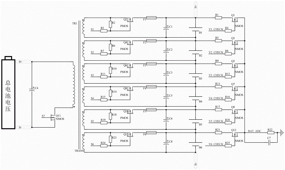
附图1为本发明的电池组自主均衡电路的原理图。FIG. 1 is a schematic diagram of the self-balancing circuit of the battery pack of the present invention.
具体实施方式Detailed ways
下面结合附图所示的实施例对本发明作进一步描述。The present invention will be further described below with reference to the embodiments shown in the accompanying drawings.
实施例一:电池组(锂电池组)包括n(n为大于或等于2的正整数)个串联的单体电池,本实施例中的电池组包括6个单体电池,分别为B1~B6。针对该电池组,设计了以下电池组自主均衡电路。Embodiment 1: The battery pack (lithium battery pack) includes n (n is a positive integer greater than or equal to 2) single cells connected in series. The battery pack in this embodiment includes 6 single cells, B1~B6 respectively. . For this battery pack, the following battery pack self-balancing circuit is designed.
该电池组自主均衡电路包括电池电压检测电路、双向储能充电电路以及控制器(MCU)。The battery pack self-balancing circuit includes a battery voltage detection circuit, a bidirectional energy storage charging circuit and a controller (MCU).
电池电压检测电路用于检测各个单体电池的电压。电池电压检测电路包括n个与各个单体电池一一对应连接的电压检测单元,每个电压检测单元的结构均相同。电压检测单元主要包括电压检测NMOS管,电压检测NMOS管的栅极接入检测控制信号,电压检测NMOS管的漏极与其对应的单体电池的正极相连接,电压检测NMOS管的源极输出电压检测信号。电压检测单元还包括第一电阻和第二电阻,电压检测NMOS管的漏极经第一电阻连接对应的单体电池的正极,电压检测NMOS管的栅极经第二电阻连接控制器。电池电压检测电路中,各个电压检测NMOS管的源极可以共接后连接控制器。共接后的电压检测NMOS管的源极经接地电阻后接地,接地电阻的两端并联有滤波电容。The battery voltage detection circuit is used to detect the voltage of each single cell. The battery voltage detection circuit includes n voltage detection units which are connected with each single battery in a one-to-one correspondence, and each voltage detection unit has the same structure. The voltage detection unit mainly includes a voltage detection NMOS tube, the gate of the voltage detection NMOS tube is connected to the detection control signal, the drain of the voltage detection NMOS tube is connected to the positive pole of the corresponding single battery, and the source output voltage of the voltage detection NMOS tube detection signal. The voltage detection unit further includes a first resistor and a second resistor, the drain of the voltage detection NMOS transistor is connected to the anode of the corresponding single battery through the first resistor, and the gate of the voltage detection NMOS transistor is connected to the controller through the second resistor. In the battery voltage detection circuit, the sources of each voltage detection NMOS transistor can be connected in common and then connected to the controller. After the common connection, the source of the voltage detection NMOS tube is grounded after the grounding resistor, and the two ends of the grounding resistor are connected in parallel with a filter capacitor.
本实施例具体为:单体电池B1对应的电压检测单元包括电压检测NMOS管Q1、第一电阻R1、第二电阻R4。电压检测NMOS管Q1的栅极连接第二电阻R4并接入检测控制信号V1_CHECK,电压检测NMOS管Q1的漏极经第一电阻R1后连接单体电池B1的正极。单体电池B2对应的电压检测单元包括电压检测NMOS管Q3、第一电阻R4、第二电阻R8。电压检测NMOS管Q2的栅极连接第二电阻R8并接入检测控制信号V2_CHECK,电压检测NMOS管Q2的漏极经第一电阻R5后连接单体电池B2的正极。单体电池B3对应的电压检测单元包括电压检测NMOS管Q5、第一电阻R9、第二电阻R13。电压检测NMOS管Q5的栅极连接第二电阻R13并接入检测控制信号V3_CHECK,电压检测NMOS管Q5的漏极经第一电阻R9后连接单体电池B3的正极。单体电池B4对应的电压检测单元包括电压检测NMOS管Q7、第一电阻R13、第二电阻R16。电压检测NMOS管Q7的栅极连接第二电阻R16并接入检测控制信号V4_CHECK,电压检测NMOS管Q7的漏极经第一电阻R13后连接单体电池B4的正极。单体电池B5对应的电压检测单元包括电压检测NMOS管Q9、第一电阻R17、第二电阻R20。电压检测NMOS管Q9的栅极连接第二电阻R20并接入检测控制信号V5_CHECK,电压检测NMOS管Q9的漏极经第一电阻R17后连接单体电池B5的正极。单体电池B6对应的电压检测单元包括电压检测NMOS管Q12、第一电阻R21、第二电阻R25。电压检测NMOS管Q12的栅极连接第二电阻R25并接入检测控制信号V6_CHECK,电压检测NMOS管Q12的漏极经第一电阻R21后连接单体电池B6的正极。电压检测NMOS管Q1的源极、电压检测NMOS管Q3的源极、电压检测NMOS管Q5的源极、电压检测NMOS管Q7的源极、电压检测NMOS管Q9的源极、电压检测NMOS管Q12的源极共接构成节点BAT_ADC,控制器连接该节点而获得电压检测信号,其经接地电阻R22后接地,接地电阻R22的两端并联有滤波电容C7。In this embodiment, the voltage detection unit corresponding to the single battery B1 includes a voltage detection NMOS transistor Q1, a first resistor R1, and a second resistor R4. The gate of the voltage detection NMOS transistor Q1 is connected to the second resistor R4 and connected to the detection control signal V1_CHECK, and the drain of the voltage detection NMOS transistor Q1 is connected to the positive electrode of the single battery B1 through the first resistor R1. The voltage detection unit corresponding to the single battery B2 includes a voltage detection NMOS transistor Q3, a first resistor R4, and a second resistor R8. The gate of the voltage detection NMOS transistor Q2 is connected to the second resistor R8 and connected to the detection control signal V2_CHECK, and the drain of the voltage detection NMOS transistor Q2 is connected to the positive electrode of the single battery B2 through the first resistor R5. The voltage detection unit corresponding to the single battery B3 includes a voltage detection NMOS transistor Q5, a first resistor R9, and a second resistor R13. The gate of the voltage detection NMOS transistor Q5 is connected to the second resistor R13 and connected to the detection control signal V3_CHECK, and the drain of the voltage detection NMOS transistor Q5 is connected to the anode of the single battery B3 through the first resistor R9. The voltage detection unit corresponding to the single battery B4 includes a voltage detection NMOS transistor Q7, a first resistor R13, and a second resistor R16. The gate of the voltage detection NMOS transistor Q7 is connected to the second resistor R16 and connected to the detection control signal V4_CHECK, and the drain of the voltage detection NMOS transistor Q7 is connected to the positive electrode of the single battery B4 through the first resistor R13. The voltage detection unit corresponding to the single battery B5 includes a voltage detection NMOS transistor Q9, a first resistor R17, and a second resistor R20. The gate of the voltage detection NMOS transistor Q9 is connected to the second resistor R20 and connected to the detection control signal V5_CHECK, and the drain of the voltage detection NMOS transistor Q9 is connected to the anode of the single battery B5 through the first resistor R17. The voltage detection unit corresponding to the single battery B6 includes a voltage detection NMOS transistor Q12, a first resistor R21, and a second resistor R25. The gate of the voltage detection NMOS transistor Q12 is connected to the second resistor R25 and connected to the detection control signal V6_CHECK, and the drain of the voltage detection NMOS transistor Q12 is connected to the positive electrode of the single battery B6 through the first resistor R21. The source of the voltage detection NMOS transistor Q1, the source of the voltage detection NMOS transistor Q3, the source of the voltage detection NMOS transistor Q5, the source of the voltage detection NMOS transistor Q7, the source of the voltage detection NMOS transistor Q9, the voltage detection NMOS transistor Q12 The sources of BAT_ADC are connected together to form a node BAT_ADC, and the controller connects to this node to obtain a voltage detection signal, which is grounded through a grounding resistor R22, and the two ends of the grounding resistor R22 are connected in parallel with a filter capacitor C7.
双向储能充电电路用于实现双向能量转移。双向储能充电电路包括储能变压器、能量转移NMOS管和n个与各个单体电池一一对应连接的结构相同的充放电单元。储能变压器包括初级线圈和n个与各个单体电池一一对应设置的次级线圈。初级线圈的一端连接电池组的正极,初级线圈的另一端连接能量转移NMOS管的漏极,能量转移NMOS管的源极连接电池组的负极,能量转移NMOS管的栅极接入能量转移控制信号。双向储能充电电路还包括电解电容,电解电容并联于电池组两端。The bidirectional energy storage charging circuit is used to realize bidirectional energy transfer. The bidirectional energy storage charging circuit includes an energy storage transformer, an energy transfer NMOS tube, and n charging and discharging units with the same structure that are connected to each single battery in a one-to-one correspondence. The energy storage transformer includes a primary coil and n secondary coils which are arranged in a one-to-one correspondence with each single cell. One end of the primary coil is connected to the positive electrode of the battery pack, the other end of the primary coil is connected to the drain of the energy transfer NMOS tube, the source of the energy transfer NMOS tube is connected to the negative electrode of the battery pack, and the gate of the energy transfer NMOS tube is connected to the energy transfer control signal . The bidirectional energy storage charging circuit also includes an electrolytic capacitor, and the electrolytic capacitor is connected in parallel with both ends of the battery pack.
充放电单元主要包括充放电PMOS管,充放电PMOS管的栅极接入充放电控制信号,充放电PMOS管的源极与对应的次级线圈的一端相连接,充放电PMOS管的漏极与对应的单体电池的正极相连接,单体电池的负极与对应的次级线圈的另一端相连接。充放电单元还包括第三电阻和第四电阻,第三电阻连接在充放电PMOS管的栅极和源极之间,充放电PMOS管的栅极经第四电阻连接控制器。充放电单元还包括保险丝和电容。充放电PMOS管的漏极经保险丝连接单体电池的正极,电容并联在单体电池两端。The charge and discharge unit mainly includes a charge and discharge PMOS tube, the gate of the charge and discharge PMOS tube is connected to the charge and discharge control signal, the source of the charge and discharge PMOS tube is connected to one end of the corresponding secondary coil, and the drain of the charge and discharge PMOS tube is connected to The positive poles of the corresponding single cells are connected to each other, and the negative poles of the single cells are connected to the other ends of the corresponding secondary coils. The charging and discharging unit further includes a third resistor and a fourth resistor, the third resistor is connected between the gate and the source of the charging and discharging PMOS tube, and the gate of the charging and discharging PMOS tube is connected to the controller through the fourth resistor. The charging and discharging unit also includes fuses and capacitors. The drain of the charge and discharge PMOS tube is connected to the positive electrode of the single battery through the fuse, and the capacitor is connected in parallel with both ends of the single battery.
本实施例具体为:储能变压器TR1包括一个初级线圈和6个次级线圈。储能变压器TR1的初级线圈的一端连接电池组的正极B+,初级线圈的另一端连接能量转移NMOS管Q11的漏极,能量转移NMOS管Q11的源极连接电池组的负极B-,能量转移NMOS管的栅极Q11接入能量转移控制信号S7。In this embodiment, the energy storage transformer TR1 includes one primary coil and six secondary coils. One end of the primary coil of the energy storage transformer TR1 is connected to the positive electrode B+ of the battery pack, the other end of the primary coil is connected to the drain of the energy transfer NMOS transistor Q11, the source electrode of the energy transfer NMOS transistor Q11 is connected to the negative electrode B- of the battery pack, and the energy transfer NMOS The gate Q11 of the tube is connected to the energy transfer control signal S7.
单体电池B1对应的充放电单元包括充放电PMOS管Q2、第三电阻R2、第四电阻R3、保险丝F1和电容C1。充放电PMOS管Q2的源极与对应的次级线圈的一端相连接,充放电PMOS管Q2的漏极经保险丝F1连接单体电池B1的正极,单体电池B1的负极连接对应的次级线圈的另一端,第三电阻R2连接在充放电PMOS管Q2的栅极和源极之间,充放电PMOS管Q2的栅极连接第四电阻R3的一端以接入能量转移控制信号S1,电容C1并联在单体电池B1两端。单体电池B2对应的充放电单元包括充放电PMOS管Q4、第三电阻R6、第四电阻R7、保险丝F2和电容C2。充放电PMOS管Q4的源极与对应的次级线圈的一端相连接,充放电PMOS管Q4的漏极经保险丝F2连接电梯电池B2的正极,电梯电池B2的负极连接对应的次级线圈的另一端,第三电阻R6连接在充放电PMOS管Q4的栅极和源极之间,充放电PMOS管Q4的栅极连接第四电阻R7的一端以接入能量转移控制信号S2,电容C2并联在电梯电池B2两端。单体电池B3对应的充放电单元包括充放电PMOS管Q6、第三电阻R10、第四电阻R11、保险丝F3和电容C3。充放电PMOS管Q6的源极与对应的次级线圈的一端相连接,充放电PMOS管Q6的漏极经保险丝F3连接单体电池B3的正极,单体电池B3的负极连接对应的次级线圈的另一端,第三电阻R10连接在充放电PMOS管Q6的栅极和源极之间,充放电PMOS管Q6的栅极连接第四电阻R11的一端以接入能量转移控制信号S3,电容C3并联在单体电池B3两端。单体电池B4对应的充放电单元包括充放电PMOS管Q8、第三电阻R14、第四电阻R15、保险丝F4和电容C5。充放电PMOS管Q8的源极与对应的次级线圈的一端相连接,充放电PMOS管Q8的漏极经保险丝F4连接单体电池B4的正极,单体电池B4的负极连接对应的次级线圈的另一端,第三电阻R14连接在充放电PMOS管Q8的栅极和源极之间,充放电PMOS管Q8的栅极连接第四电阻R15的一端以接入能量转移控制信号S4,电容C5并联在单体电池B4两端。单体电池B5对应的充放电单元包括充放电PMOS管Q10、第三电阻R18、第四电阻R19、保险丝F5和电容C6。充放电PMOS管Q10的源极与对应的次级线圈的一端相连接,充放电PMOS管Q10的漏极经保险丝F5连接单体电池B5的正极,单体电池B5的负极连接对应的次级线圈的另一端,第三电阻R18连接在充放电PMOS管Q10的栅极和源极之间,充放电PMOS管Q10的栅极连接第四电阻R19的一端以接入能量转移控制信号S5,电容C6并联在单体电池B5两端。单体电池B6对应的充放电单元包括充放电PMOS管Q13、第三电阻R23、第四电阻R24、保险丝F6和电容C8。充放电PMOS管Q13的源极与对应的次级线圈的一端相连接,充放电PMOS管Q13的漏极经保险丝F6连接单体电池B6的正极,单体电池B6的负极连接对应的次级线圈的另一端,第三电阻R23连接在充放电PMOS管Q13的栅极和源极之间,充放电PMOS管Q13的栅极连接第四电阻R24的一端以接入能量转移控制信号S6,电容C8并联在单体电池B6两端。The charging and discharging unit corresponding to the single battery B1 includes a charging and discharging PMOS transistor Q2, a third resistor R2, a fourth resistor R3, a fuse F1 and a capacitor C1. The source of the charge and discharge PMOS transistor Q2 is connected to one end of the corresponding secondary coil, the drain of the charge and discharge PMOS transistor Q2 is connected to the positive electrode of the single battery B1 through the fuse F1, and the negative electrode of the single battery B1 is connected to the corresponding secondary coil. The other end of the third resistor R2 is connected between the gate and the source of the charge and discharge PMOS transistor Q2, the gate of the charge and discharge PMOS transistor Q2 is connected to one end of the fourth resistor R3 to access the energy transfer control signal S1, and the capacitor C1 It is connected in parallel at both ends of the single battery B1. The charging and discharging unit corresponding to the single battery B2 includes a charging and discharging PMOS transistor Q4, a third resistor R6, a fourth resistor R7, a fuse F2 and a capacitor C2. The source of the charge and discharge PMOS tube Q4 is connected to one end of the corresponding secondary coil, the drain of the charge and discharge PMOS tube Q4 is connected to the positive pole of the elevator battery B2 through the fuse F2, and the negative pole of the elevator battery B2 is connected to the other side of the corresponding secondary coil. One end, the third resistor R6 is connected between the gate and the source of the charge and discharge PMOS transistor Q4, the gate of the charge and discharge PMOS transistor Q4 is connected to one end of the fourth resistor R7 to access the energy transfer control signal S2, and the capacitor C2 is connected in parallel with Both ends of elevator battery B2. The charging and discharging unit corresponding to the single battery B3 includes a charging and discharging PMOS transistor Q6, a third resistor R10, a fourth resistor R11, a fuse F3 and a capacitor C3. The source of the charge and discharge PMOS transistor Q6 is connected to one end of the corresponding secondary coil, the drain of the charge and discharge PMOS transistor Q6 is connected to the positive electrode of the single battery B3 through the fuse F3, and the negative electrode of the single battery B3 is connected to the corresponding secondary coil. The other end of the third resistor R10 is connected between the gate and the source of the charge and discharge PMOS transistor Q6, and the gate of the charge and discharge PMOS transistor Q6 is connected to one end of the fourth resistor R11 to access the energy transfer control signal S3, and the capacitor C3 It is connected in parallel at both ends of the single battery B3. The charging and discharging unit corresponding to the single battery B4 includes a charging and discharging PMOS transistor Q8, a third resistor R14, a fourth resistor R15, a fuse F4 and a capacitor C5. The source of the charge and discharge PMOS transistor Q8 is connected to one end of the corresponding secondary coil, the drain of the charge and discharge PMOS transistor Q8 is connected to the positive electrode of the single battery B4 through the fuse F4, and the negative electrode of the single battery B4 is connected to the corresponding secondary coil. The other end of the third resistor R14 is connected between the gate and the source of the charge and discharge PMOS transistor Q8, and the gate of the charge and discharge PMOS transistor Q8 is connected to one end of the fourth resistor R15 to access the energy transfer control signal S4, and the capacitor C5 Connected in parallel at both ends of the single battery B4. The charging and discharging unit corresponding to the single battery B5 includes a charging and discharging PMOS transistor Q10, a third resistor R18, a fourth resistor R19, a fuse F5 and a capacitor C6. The source of the charge and discharge PMOS transistor Q10 is connected to one end of the corresponding secondary coil, the drain of the charge and discharge PMOS transistor Q10 is connected to the positive electrode of the single battery B5 through the fuse F5, and the negative electrode of the single battery B5 is connected to the corresponding secondary coil. The other end of the third resistor R18 is connected between the gate and the source of the charge and discharge PMOS transistor Q10, the gate of the charge and discharge PMOS transistor Q10 is connected to one end of the fourth resistor R19 to access the energy transfer control signal S5, the capacitor C6 It is connected in parallel at both ends of the single battery B5. The charging and discharging unit corresponding to the single battery B6 includes a charging and discharging PMOS transistor Q13, a third resistor R23, a fourth resistor R24, a fuse F6 and a capacitor C8. The source of the charge and discharge PMOS transistor Q13 is connected to one end of the corresponding secondary coil, the drain of the charge and discharge PMOS transistor Q13 is connected to the positive electrode of the single battery B6 through the fuse F6, and the negative electrode of the single battery B6 is connected to the corresponding secondary coil. The other end of the third resistor R23 is connected between the gate and the source of the charge and discharge PMOS transistor Q13, the gate of the charge and discharge PMOS transistor Q13 is connected to one end of the fourth resistor R24 to access the energy transfer control signal S6, the capacitor C8 It is connected in parallel at both ends of the single battery B6.
控制器用于根据各个单体电池的电压控制分别控制电压检测NMOS管、能量转移NMOS、充放电PMOS管而均衡电池组电压。控制器与各个电压检测NMOS管的源极相连接,用于接收电压检测信号;控制器分别与各个电压检测NMOS管的栅极、能量转移NMOS管的栅极、各个充放电PMOS管的栅极相连接,用于输出各路检测控制信号、能量转移控制信号、充放电控制信号。The controller is used to control the voltage detection NMOS tube, the energy transfer NMOS tube, and the charge and discharge PMOS tube respectively to balance the voltage of the battery pack according to the voltage control of each single cell. The controller is connected to the source of each voltage detection NMOS tube for receiving the voltage detection signal; the controller is respectively connected to the gate of each voltage detection NMOS tube, the gate of the energy transfer NMOS tube, and the gate of each charge and discharge PMOS tube are connected to each other, and are used to output various detection control signals, energy transfer control signals, and charge and discharge control signals.
上述方案中,电池电压检测电路主要使用分压原理检测,当需要检测某个单体电池的电压时,只需将对应的电压检测NMOS管的栅极置高电平,即可在电压检测NMOS管的源极,即BAT_ADC处山上呢个一个电压,控制器的ADC端口通过读取BAT_ADC的电压即可计算出该单体电池的电压。在BAT_ADC处并联的滤波电容C7可有效滤除杂波,提高检测准确性。In the above scheme, the battery voltage detection circuit mainly uses the voltage division principle to detect. When the voltage of a single battery needs to be detected, it is only necessary to set the gate of the corresponding voltage detection NMOS tube to a high level, and then the NMOS can be detected in the voltage. The source of the tube, that is, a voltage on the mountain at BAT_ADC, the ADC port of the controller can calculate the voltage of the single battery by reading the voltage of BAT_ADC. The filter capacitor C7 connected in parallel at BAT_ADC can effectively filter out clutter and improve the detection accuracy.
双向储能充电电路是一个反激式的电源电路,其中电解电容C5并联在电池组上,起到储能滤波的作用。当需要给电池组充电或者放电时,只需要打开对应的充放电PMOS管即可。The bidirectional energy storage charging circuit is a flyback power supply circuit, in which the electrolytic capacitor C5 is connected in parallel with the battery pack to play the role of energy storage filtering. When the battery pack needs to be charged or discharged, it is only necessary to turn on the corresponding charge and discharge PMOS tube.
电池组自主均衡电路控制实现电池组均衡的方法为:The method of battery pack self-balancing circuit control to achieve battery pack balance is:
控制器对各个单体电池进行扫描,通过电池电压检测电路的各个电压检测单元获得各个单体电池的电压并计算出电压平均值,再选出电压与电压平均值的差值最大的单体电池Bx并判断选出的单体电池Bx的电压低于或高于电压平均值,若选出的单体电池Bx的电压低于电压平均值,必须使该单体电池Bx的电压增加,则执行底部均衡方法,若选出的单体电池的电压高于电压平均值,必须使该单体电池Bx的电压下降,则执行顶部均衡方法。The controller scans each single cell, obtains the voltage of each single cell through each voltage detection unit of the battery voltage detection circuit, calculates the voltage average value, and then selects the single cell with the largest difference between the voltage and the voltage average value. Bx and judge that the voltage of the selected single battery Bx is lower or higher than the voltage average value. If the voltage of the selected single battery Bx is lower than the voltage average value, the voltage of the single battery Bx must be increased. In the bottom equalization method, if the voltage of the selected single cell is higher than the voltage average value, the voltage of the single cell Bx must be lowered, and then the top equalization method is performed.
底部均衡方法为:控制器先控制能量转移NMOS 管Q11导通,使电池组对储能变压器TR1的初级线圈充电,然后控制器控制能量转移NMOS 管Q11关断,并控制选出的单体电池Bx对应的充放电PMOS管导通,使储能变压器TR1的初级线圈上的能量转移到选出的单体电池Bx对应的次级线圈上,并为选出的单体电池Bx充电。在应用时,能量转移NMOS 管Q11的开关频率应该在25KHZ以上,避免储能变压器TR1出现啸叫噪音。如此循环控制,直到所有的单体电池电压都达到均衡目标。The bottom equalization method is as follows: the controller first controls the energy transfer NMOS transistor Q11 to turn on, so that the battery pack charges the primary coil of the energy storage transformer TR1, and then the controller controls the energy transfer NMOS transistor Q11 to turn off, and controls the selected single battery. The charge and discharge PMOS transistor corresponding to Bx is turned on, so that the energy on the primary coil of the energy storage transformer TR1 is transferred to the secondary coil corresponding to the selected single battery Bx, and the selected single battery Bx is charged. In application, the switching frequency of the energy transfer NMOS transistor Q11 should be above 25KHZ to avoid whistling noise in the energy storage transformer TR1. This cycle of control until all single cell voltages reach the equilibrium target.
例如,单体电池B3的电压与电压平均值的差值最大且低于电压平均值,则需要给单体电池B3充电。先控制能量转移NMOS 管Q11导通,使电池组对储能变压器TR1的初级线圈充电,再控制能量转移NMOS 管Q11关断,控制单体电池B3对应的充放电PMOS管Q6导通,,使储能变压器TR1的初级线圈上的能量转移到单体电池B3对应的次级线圈上,并为单体电池B3充电。如此循环控制,直到所有的单体电池电压都达到均衡目标。For example, if the difference between the voltage of the single battery B3 and the average voltage is the largest and lower than the average voltage, the single battery B3 needs to be charged. First, the energy transfer NMOS transistor Q11 is controlled to be turned on, so that the battery pack charges the primary coil of the energy storage transformer TR1, and then the energy transfer NMOS transistor Q11 is controlled to be turned off, and the charge and discharge PMOS transistor Q6 corresponding to the single battery B3 is controlled to be turned on, so that the The energy on the primary coil of the energy storage transformer TR1 is transferred to the secondary coil corresponding to the unit battery B3 and charges the unit battery B3. This cycle of control until all single cell voltages reach the equilibrium target.
顶部均衡方法为:控制器先控制选出的单体电池Bx对应的充放电PMOS管导通,使选出的单体电池Bx为其对应的次级线圈充电,然后控制器控制选出的单体电池Bx对应的充放电PMOS管关断,并控制能量转移NMOS 管Q11导通,使选出的单体电池Bx对应的次级线圈上的能量转移到初级线圈上,并为电池组充电。The top equalization method is as follows: the controller first controls the charging and discharging PMOS tube corresponding to the selected single battery Bx to conduct, so that the selected single battery Bx is charged to its corresponding secondary coil, and then the controller controls the selected single battery Bx. The charge and discharge PMOS tube corresponding to the bulk battery Bx is turned off, and the energy transfer NMOS tube Q11 is controlled to be turned on, so that the energy on the secondary coil corresponding to the selected single battery Bx is transferred to the primary coil and charges the battery pack.
例如,单体电池B2的电压与电压平均值的差值最大且高于电压平均值,则需要使单体电池B2放电。先控制单体电池B2对应的充放电PMOS管Q4导通,电流从单体电池B2流向储能变压器TR1的次级线圈,使单体电池B2为其对应的次级线圈充电。由于自感的存在,电流随时间线性增大,由于自感是变压器固有的特性,因此充放电PMOS管Q4的导通时间将决定电流的大小,单体电池B2转移出的能量以磁场的形式得到存储。然后控制单体电池B2对应的充放电PMOS管Q4关断,并控制能量转移NMOS 管Q11导通,使单体电池B2对应的次级线圈上的能量转移到初级线圈上,并为电池组充电。如此循环控制,直到所有的电池电压都达到均衡目标。For example, if the difference between the voltage of the unit cell B2 and the average voltage value is the largest and higher than the average value of the voltage, the unit battery B2 needs to be discharged. First, control the charging and discharging PMOS transistor Q4 corresponding to the single battery B2 to conduct, and the current flows from the single battery B2 to the secondary coil of the energy storage transformer TR1, so that the single battery B2 is charged to its corresponding secondary coil. Due to the existence of the self-inductance, the current increases linearly with time. Since the self-inductance is an inherent characteristic of the transformer, the conduction time of the charge and discharge PMOS transistor Q4 will determine the magnitude of the current, and the energy transferred from the single battery B2 is in the form of a magnetic field. get stored. Then control the charge and discharge PMOS transistor Q4 corresponding to the single battery B2 to turn off, and control the energy transfer NMOS transistor Q11 to turn on, so that the energy on the secondary coil corresponding to the single battery B2 is transferred to the primary coil, and the battery pack is charged. . This cycle of control until all battery voltages reach the equilibrium target.
上述电池组自主均衡电路是以变压器作为能量转移的载体,期间并不消耗能量,可使整个电池组实现自主均衡,整个线路结构简单,转移效率高。The above-mentioned battery pack self-balancing circuit uses the transformer as the carrier of energy transfer, and does not consume energy during the period, so that the entire battery pack can achieve self-balancing, the entire circuit structure is simple, and the transfer efficiency is high.
上述实施例只为说明本发明的技术构思及特点,其目的在于让熟悉此项技术的人士能够了解本发明的内容并据以实施,并不能以此限制本发明的保护范围。凡根据本发明精神实质所作的等效变化或修饰,都应涵盖在本发明的保护范围之内。The above-mentioned embodiments are only intended to illustrate the technical concept and characteristics of the present invention, and the purpose thereof is to enable those who are familiar with the art to understand the content of the present invention and implement them accordingly, and cannot limit the protection scope of the present invention. All equivalent changes or modifications made according to the spirit of the present invention should be included within the protection scope of the present invention.
Claims (10)
Priority Applications (1)
| Application Number | Priority Date | Filing Date | Title |
|---|---|---|---|
| CN202010540687.3A CN111641237A (en) | 2020-06-15 | 2020-06-15 | Battery pack self-balancing circuit |
Applications Claiming Priority (1)
| Application Number | Priority Date | Filing Date | Title |
|---|---|---|---|
| CN202010540687.3A CN111641237A (en) | 2020-06-15 | 2020-06-15 | Battery pack self-balancing circuit |
Publications (1)
| Publication Number | Publication Date |
|---|---|
| CN111641237A true CN111641237A (en) | 2020-09-08 |
Family
ID=72332635
Family Applications (1)
| Application Number | Title | Priority Date | Filing Date |
|---|---|---|---|
| CN202010540687.3A Pending CN111641237A (en) | 2020-06-15 | 2020-06-15 | Battery pack self-balancing circuit |
Country Status (1)
| Country | Link |
|---|---|
| CN (1) | CN111641237A (en) |
Cited By (4)
| Publication number | Priority date | Publication date | Assignee | Title |
|---|---|---|---|---|
| CN113991765A (en) * | 2021-09-23 | 2022-01-28 | 宁波中车新能源科技有限公司 | Balancing device and method for energy transfer in super capacitor module |
| CN114678911A (en) * | 2020-12-24 | 2022-06-28 | 圣邦微电子(北京)股份有限公司 | A bidirectional detection circuit for charging and discharging current |
| CN114899917A (en) * | 2022-05-24 | 2022-08-12 | 广东格兰仕微波生活电器制造有限公司 | Equalization control circuit and method for battery pack, electronic device, and storage medium |
| CN116896128A (en) * | 2023-06-09 | 2023-10-17 | 国网上海市电力公司 | A low-side MOSFET control device for large-capacity energy storage units |
Citations (2)
| Publication number | Priority date | Publication date | Assignee | Title |
|---|---|---|---|---|
| CN104242395A (en) * | 2014-09-23 | 2014-12-24 | 重庆星联云科科技发展有限公司 | Active equalization circuit and equalization method of series batteries of single transformer |
| CN209516650U (en) * | 2018-12-26 | 2019-10-18 | 苏州易美新思新能源科技有限公司 | A low power consumption self-balancing battery voltage sampling circuit |
-
2020
- 2020-06-15 CN CN202010540687.3A patent/CN111641237A/en active Pending
Patent Citations (2)
| Publication number | Priority date | Publication date | Assignee | Title |
|---|---|---|---|---|
| CN104242395A (en) * | 2014-09-23 | 2014-12-24 | 重庆星联云科科技发展有限公司 | Active equalization circuit and equalization method of series batteries of single transformer |
| CN209516650U (en) * | 2018-12-26 | 2019-10-18 | 苏州易美新思新能源科技有限公司 | A low power consumption self-balancing battery voltage sampling circuit |
Non-Patent Citations (1)
| Title |
|---|
| 高丽丽等: "矿用单轨机车锂离子电池组均衡电路的研究", 《煤矿机械》 * |
Cited By (4)
| Publication number | Priority date | Publication date | Assignee | Title |
|---|---|---|---|---|
| CN114678911A (en) * | 2020-12-24 | 2022-06-28 | 圣邦微电子(北京)股份有限公司 | A bidirectional detection circuit for charging and discharging current |
| CN113991765A (en) * | 2021-09-23 | 2022-01-28 | 宁波中车新能源科技有限公司 | Balancing device and method for energy transfer in super capacitor module |
| CN114899917A (en) * | 2022-05-24 | 2022-08-12 | 广东格兰仕微波生活电器制造有限公司 | Equalization control circuit and method for battery pack, electronic device, and storage medium |
| CN116896128A (en) * | 2023-06-09 | 2023-10-17 | 国网上海市电力公司 | A low-side MOSFET control device for large-capacity energy storage units |
Similar Documents
| Publication | Publication Date | Title |
|---|---|---|
| CN101740827B (en) | Active equalization system of lithium-ion power battery and equalization method thereof | |
| CN101882699B (en) | Charge and discharge balancing control method for power battery pack | |
| CN111641237A (en) | Battery pack self-balancing circuit | |
| CN109950949B (en) | Three-level active equalization circuit of lithium battery pack for energy storage | |
| CN107658936B (en) | A battery monitoring and balancing system and control method thereof | |
| CN103236732B (en) | Active equalizing system and equalizing method for power lithium ion battery pack | |
| CN102545332B (en) | Method and system for equalizing electric quantity of single batteries | |
| CN105429226A (en) | High-capacity charging-discharging battery management system | |
| CN105449296A (en) | Nondestructive equilibrium management system of modular high-power battery pack | |
| CN105553026A (en) | Battery pack electricity equalization circuit and equalization method | |
| CN108511817A (en) | A kind of lithium-ion-power cell group active equalization circuit | |
| CN108539813A (en) | A kind of lithium-ion-power cell active equalization method | |
| CN108039750A (en) | A kind of energy-storage system, balanced energy storage method, battery management unit and storage medium | |
| CN112086698A (en) | A kind of active equalization circuit and method for cascade utilization of retired power battery | |
| CN103457325A (en) | Direct-type lithium ion battery lossless equilibration circuit and equilibration control method | |
| CN111682270A (en) | Series-parallel switching device and battery pack including series-parallel switching device | |
| CN106329640B (en) | A kind of battery charging equalization apparatus and method | |
| CN108039759A (en) | A kind of lithium-ion battery systems multiplex mode high efficiency energy balanced device and its control method | |
| CN111181224A (en) | Charging system for multi-section series battery pack and charging method thereof | |
| CN110190638B (en) | A fast balancing inductive topological circuit for lithium batteries | |
| CN106451604A (en) | Dual-battery energy storage system | |
| CN102751757A (en) | Lithium ion battery pack electricity quantity equalization method and system | |
| CN110729795A (en) | An energy storage power station and its battery equalization control method | |
| CN201985550U (en) | Series lithium ion power battery pack with automatic charge-discharge balance | |
| CN201758299U (en) | Charge-discharge automatic balancing lithium-ion power series battery |
Legal Events
| Date | Code | Title | Description |
|---|---|---|---|
| PB01 | Publication | ||
| PB01 | Publication | ||
| SE01 | Entry into force of request for substantive examination | ||
| SE01 | Entry into force of request for substantive examination | ||
| RJ01 | Rejection of invention patent application after publication |
Application publication date: 20200908 |
|
| RJ01 | Rejection of invention patent application after publication |