CN111663287A - washing machine - Google Patents
washing machine Download PDFInfo
- Publication number
- CN111663287A CN111663287A CN201910171701.4A CN201910171701A CN111663287A CN 111663287 A CN111663287 A CN 111663287A CN 201910171701 A CN201910171701 A CN 201910171701A CN 111663287 A CN111663287 A CN 111663287A
- Authority
- CN
- China
- Prior art keywords
- output shaft
- washing machine
- wire
- pulsator
- inner cylinder
- Prior art date
- Legal status (The legal status is an assumption and is not a legal conclusion. Google has not performed a legal analysis and makes no representation as to the accuracy of the status listed.)
- Granted
Links
Images


Classifications
-
- D—TEXTILES; PAPER
- D06—TREATMENT OF TEXTILES OR THE LIKE; LAUNDERING; FLEXIBLE MATERIALS NOT OTHERWISE PROVIDED FOR
- D06F—LAUNDERING, DRYING, IRONING, PRESSING OR FOLDING TEXTILE ARTICLES
- D06F23/00—Washing machines with receptacles, e.g. perforated, having a rotary movement, e.g. oscillatory movement, the receptacle serving both for washing and for centrifugally separating water from the laundry
- D06F23/04—Washing machines with receptacles, e.g. perforated, having a rotary movement, e.g. oscillatory movement, the receptacle serving both for washing and for centrifugally separating water from the laundry and rotating or oscillating about a vertical axis
-
- D—TEXTILES; PAPER
- D06—TREATMENT OF TEXTILES OR THE LIKE; LAUNDERING; FLEXIBLE MATERIALS NOT OTHERWISE PROVIDED FOR
- D06F—LAUNDERING, DRYING, IRONING, PRESSING OR FOLDING TEXTILE ARTICLES
- D06F37/00—Details specific to washing machines covered by groups D06F21/00 - D06F25/00
- D06F37/26—Casings; Tubs
- D06F37/267—Tubs specially adapted for mounting thereto components or devices not provided for in preceding subgroups
-
- D—TEXTILES; PAPER
- D06—TREATMENT OF TEXTILES OR THE LIKE; LAUNDERING; FLEXIBLE MATERIALS NOT OTHERWISE PROVIDED FOR
- D06F—LAUNDERING, DRYING, IRONING, PRESSING OR FOLDING TEXTILE ARTICLES
- D06F39/00—Details of washing machines not specific to a single type of machines covered by groups D06F9/00 - D06F27/00
-
- Y—GENERAL TAGGING OF NEW TECHNOLOGICAL DEVELOPMENTS; GENERAL TAGGING OF CROSS-SECTIONAL TECHNOLOGIES SPANNING OVER SEVERAL SECTIONS OF THE IPC; TECHNICAL SUBJECTS COVERED BY FORMER USPC CROSS-REFERENCE ART COLLECTIONS [XRACs] AND DIGESTS
- Y02—TECHNOLOGIES OR APPLICATIONS FOR MITIGATION OR ADAPTATION AGAINST CLIMATE CHANGE
- Y02B—CLIMATE CHANGE MITIGATION TECHNOLOGIES RELATED TO BUILDINGS, e.g. HOUSING, HOUSE APPLIANCES OR RELATED END-USER APPLICATIONS
- Y02B40/00—Technologies aiming at improving the efficiency of home appliances, e.g. induction cooking or efficient technologies for refrigerators, freezers or dish washers
Landscapes
- Engineering & Computer Science (AREA)
- Textile Engineering (AREA)
- Control Of Washing Machine And Dryer (AREA)
- Connection Of Motors, Electrical Generators, Mechanical Devices, And The Like (AREA)
Abstract
本发明属于电器制造技术领域,具体涉及一种洗衣机。本发明旨在解决现有导线在不断的扭转下就会发生破损或者断裂的问题。本发明的洗衣机包括:外筒;内筒,可转动的设置在所述外筒内,所述内筒具有一用于投放衣物的开口;驱动机构,其输出轴穿过所述外筒并与所述内筒传动连接,以驱动所述内筒沿一旋转轴线转动;磁体,固定在所述外筒上,以在所述输出轴的周围形成磁场;线圈,安装在所述输出轴上,该线圈用于在所述输出轴的驱动下在所述磁场内旋转以产生感应电流;用电装置,设置在所述内筒中,且与所述线圈供电连接。
The invention belongs to the technical field of electrical appliance manufacturing, and in particular relates to a washing machine. The present invention aims to solve the problem that the existing wires will be damaged or broken under constant twisting. The washing machine of the present invention comprises: an outer tub; an inner tub, which is rotatably arranged in the outer tub, the inner tub has an opening for putting clothes in; a driving mechanism, the output shaft of which passes through the outer tub and is connected with the outer tub. The inner cylinder is connected in a transmission to drive the inner cylinder to rotate along a rotation axis; a magnet is fixed on the outer cylinder to form a magnetic field around the output shaft; a coil is installed on the output shaft, The coil is used to rotate in the magnetic field under the drive of the output shaft to generate an induced current; an electrical device is arranged in the inner cylinder and is connected to the coil for power supply.
Description
技术领域technical field
本发明属于电器制造技术领域,具体涉及一种洗衣机。The invention belongs to the technical field of electrical appliance manufacturing, and in particular relates to a washing machine.
背景技术Background technique
洗衣机是一种利用电能产生机械作用来洗涤衣物等的清洁电器。随着洗衣机行业的发展,消费者对洗衣机功能等的要求也越来越高。A washing machine is a cleaning appliance that uses electrical energy to generate mechanical action to wash clothes and the like. With the development of the washing machine industry, consumers have higher and higher requirements for washing machine functions.
相关技术中,洗衣机包括箱体,箱体内设置有外筒,外筒中设置有可旋转的内筒;箱体的顶端设置有控制盘座,控制盘座上设置有主电路板以及与该主电路板通信连接的机械按键或者触控面板;内筒中有时会设置诸如指示灯一类的用电装置。在装配时,设置在内筒中的用电装置需要通过导线与主电路板电连接,以便由主电路板为该用电装置供电。但是,在实际装配时发现,由于内筒在工作时会相对于外筒转动,从主电路板引出的导线的一部分会跟随内筒旋转,随着时间的推移,导线在不断的扭转下就会发生破损或者断裂。In the related art, the washing machine includes a box body, an outer cylinder is arranged in the box body, and a rotatable inner cylinder is arranged in the outer cylinder; a control panel seat is arranged at the top of the box body, and a main circuit board is arranged on the control panel seat and is connected with the main circuit. A mechanical button or a touch panel for the communication connection of the board; sometimes an electrical device such as an indicator light is set in the inner cylinder. During assembly, the electrical device disposed in the inner cylinder needs to be electrically connected to the main circuit board through wires, so that the electrical device can be powered by the main circuit board. However, during the actual assembly, it was found that since the inner cylinder will rotate relative to the outer cylinder during operation, part of the wires drawn from the main circuit board will rotate with the inner cylinder. Broken or broken.
相应地,本领域需要一种洗衣机来解决上述问题。Accordingly, there is a need in the art for a washing machine to solve the above problems.
发明内容SUMMARY OF THE INVENTION
为了解决现有技术中的上述或者其他潜在问题,本发明提供了一种洗衣机,包括:外筒;内筒,可转动的设置在所述外筒内,所述内筒具有一用于投放衣物的开口;驱动机构,其输出轴穿过所述外筒并与所述内筒传动连接,以驱动所述内筒沿一旋转轴线转动;磁体,固定在所述外筒上,以在所述输出轴的周围形成磁场;线圈,安装在所述输出轴上,该线圈用于在所述输出轴的驱动下在所述磁场内旋转以产生感应电流;用电装置,设置在所述内筒中,且与所述线圈供电连接。In order to solve the above or other potential problems in the prior art, the present invention provides a washing machine, comprising: an outer tub; an inner tub, which is rotatably arranged in the outer tub, and the inner tub has a opening; a driving mechanism, the output shaft of which passes through the outer cylinder and is drive-connected with the inner cylinder to drive the inner cylinder to rotate along a rotation axis; a magnet is fixed on the outer cylinder to drive the inner cylinder to rotate A magnetic field is formed around the output shaft; a coil is installed on the output shaft, and the coil is used to rotate in the magnetic field under the driving of the output shaft to generate an induced current; an electrical device is arranged in the inner cylinder , and is connected to the coil for power supply.
在上述洗衣机的优选技术方案中,所述旋转轴线水平设置或者所述旋转轴线与水平面之间具有一锐角。In the preferred technical solution of the above washing machine, the rotation axis is arranged horizontally or there is an acute angle between the rotation axis and the horizontal plane.
在上述洗衣机的优选技术方案中,所述旋转轴线竖直设置。In the preferred technical solution of the above washing machine, the rotation axis is arranged vertically.
在上述蒸洗衣机的优选技术方案中,所述用电装置包括安装在所述内筒上的指示器,所述指示器用于向用户提供视觉或者听觉指示信号。In the preferred technical solution of the above steaming washing machine, the electrical device includes an indicator mounted on the inner tub, and the indicator is used to provide a visual or audible indication signal to the user.
在上述洗衣机的优选技术方案中,所述指示器包括指示灯。In the preferred technical solution of the above washing machine, the indicator includes an indicator light.
在上述洗衣机的优选技术方案中,所述指示灯为多个,多个所述指示灯至少包括两种颜色。In the preferred technical solution of the above washing machine, there are a plurality of the indicator lights, and the plurality of the indicator lights include at least two colors.
在上述洗衣机的优选技术方案中,所述指示器还包括控制器,所述控制器与所述线圈供电连接,并且所述控制器用于控制所述指示灯的开闭。In the preferred technical solution of the above washing machine, the indicator further includes a controller, the controller is connected to the coil for power supply, and the controller is used to control the opening and closing of the indicator light.
在上述洗衣机的优选技术方案中,所述指示灯为多个,所述控制器用于控制多个所述指示灯的开闭时间、开闭频率。In a preferred technical solution of the above washing machine, there are a plurality of the indicator lights, and the controller is used to control the on-off time and on-off frequency of the plurality of indicator lights.
在上述洗衣机的优选技术方案中,多个所述指示灯至少包括两种颜色。In the preferred technical solution of the above washing machine, a plurality of the indicator lights include at least two colors.
在上述洗衣机的优选技术方案中,所述磁体呈盘状,所述磁体和线圈沿所述输出轴的轴线方向相对设置且二者之间形成有气隙。In the preferred technical solution of the above washing machine, the magnet is in the shape of a disk, and the magnet and the coil are arranged opposite to each other along the axis direction of the output shaft with an air gap formed therebetween.
在上述洗衣机的优选技术方案中,所述洗衣机还包括设置于所述内筒内的波轮机构,所述波轮机构与所述驱动机构的输出轴传动连接,以驱动所述波轮机构相对于所述内筒转动。In a preferred technical solution of the above washing machine, the washing machine further includes a pulsator mechanism disposed in the inner tub, and the pulsator mechanism is drivingly connected with the output shaft of the driving mechanism to drive the pulsator mechanism to face each other. rotate in the inner cylinder.
在上述洗衣机的优选技术方案中,所述用电装置中的指示灯设置在所述波轮机构上。In the preferred technical solution of the above washing machine, the indicator light in the electric device is arranged on the pulsator mechanism.
在上述洗衣机的优选技术方案中,所述波轮机构包括波轮盘,所述波轮盘开设有沿驱动机构输出轴的轴向贯穿的通孔,所述通孔的两端分别安装有轴套和波轮盖;所述轴套与所述驱动机构的输出轴连接;所述波轮盖与所述波轮盘之间密封;所述指示灯设置在所述通孔内。In a preferred technical solution of the above washing machine, the pulsator mechanism includes a pulsator disc, and the pulsator disc is provided with a through hole penetrating in the axial direction of the output shaft of the driving mechanism, and shafts are respectively installed at both ends of the through hole. a sleeve and a pulsator cover; the shaft sleeve is connected with the output shaft of the driving mechanism; the pulsator cover and the pulsator disc are sealed; the indicator light is arranged in the through hole.
在上述洗衣机的优选技术方案中,所述用电装置通过导线与所述线圈电连接;所述导线包括第一导线,所述输出轴为中空轴,所述第一导线穿设在所述中空轴内。In the preferred technical solution of the above washing machine, the electrical device is electrically connected to the coil through a wire; the wire includes a first wire, the output shaft is a hollow shaft, and the first wire passes through the hollow shaft inside the shaft.
在上述洗衣机的优选技术方案中,所述轴套上设置有沿其轴向延伸的第二过线孔,所述导线还包括第二导线,所述第二导线穿设在所述第二过线孔中。In the preferred technical solution of the above washing machine, the shaft sleeve is provided with a second wire hole extending along the axial direction thereof, the wire further includes a second wire, and the second wire passes through the second wire in the wire hole.
在上述洗衣机的优选技术方案中,所述输出轴上安装有与所述第一导线电连接的第一导电件,所述轴套设置有与所述第二导线电连接的第二导电件,所述第一导电件可相对于所述第二导电件转动并始终与所述第二导电件电连接。In a preferred technical solution of the above washing machine, a first conductive member electrically connected to the first wire is installed on the output shaft, and a second conductive member electrically connected to the second wire is installed on the shaft sleeve, The first conductive member is rotatable relative to the second conductive member and is always electrically connected to the second conductive member.
在上述洗衣机的优选技术方案中,所述第一导电件和第二导电件形成导电轴承或导电滑环。In the preferred technical solution of the above washing machine, the first conductive member and the second conductive member form a conductive bearing or a conductive slip ring.
所述内筒的侧壁或者内筒的底部上设置有线屑过滤器,所述用电装置安装在所述线屑过滤器上。A lint filter is provided on the side wall of the inner cylinder or the bottom of the inner cylinder, and the electrical device is installed on the lint filter.
所述用电装置中的指示灯为多个;所述内筒的顶部安装有平衡环,多个所述指示灯均匀设置在所述平衡环上。There are a plurality of indicator lights in the electric device; a gimbal ring is installed on the top of the inner cylinder, and a plurality of the indicator lights are evenly arranged on the gimbal ring.
本领域技术人员能够理解的是,本发明的洗衣机,包括:外筒、内筒、驱动机构、磁体、线圈及用电装置;其中,磁体固定在所述外筒上以在所述输出轴的周围形成磁场,线圈安装在所述输出轴上以所述输出轴的驱动下在所述磁场内旋转以产生感应电流并提供给设置在内筒中的用电装置。通过上述设置,从线圈引出的导线可从所述输出轴进入内筒与用电装置电连接,导线不会随着内筒的旋转而发生扭转,从而也就不容易破损或者断裂,进而提高了其使用寿命。此外,通过利用驱动机构自身的旋转运动产生电能提供给用电装置,还有助于节能。It can be understood by those skilled in the art that the washing machine of the present invention includes: an outer tub, an inner tub, a driving mechanism, a magnet, a coil and an electrical device; wherein, the magnet is fixed on the outer tub so as to be at the position of the output shaft. A magnetic field is formed around, and the coil is installed on the output shaft to rotate in the magnetic field under the driving of the output shaft to generate an induced current and supply it to an electrical device provided in the inner cylinder. Through the above arrangement, the wire drawn from the coil can enter the inner cylinder from the output shaft to be electrically connected to the electrical device, and the wire will not be twisted with the rotation of the inner cylinder, so that it is not easy to be damaged or broken, thereby improving the performance. its service life. In addition, by utilizing the rotational motion of the driving mechanism itself to generate electrical energy and supply it to the electrical device, it also contributes to energy saving.
附图说明Description of drawings
下面参照附图并结合洗衣机来描述本发明的洗衣机的优选实施方式。附图为:Preferred embodiments of the washing machine of the present invention will be described below with reference to the accompanying drawings and in conjunction with the washing machine. Attached is:
图1是本发明实施例的的洗衣机的局部结构示意图一;Fig. 1 is the partial structure schematic diagram 1 of the washing machine of the embodiment of the present invention;
图2是本发明实施例的洗衣机中发电装置及输出轴的结构示意图;2 is a schematic structural diagram of a power generating device and an output shaft in a washing machine according to an embodiment of the present invention;
图3是本发明实施例的的洗衣机的局部结构示意图二;3 is a second partial structural schematic diagram of a washing machine according to an embodiment of the present invention;
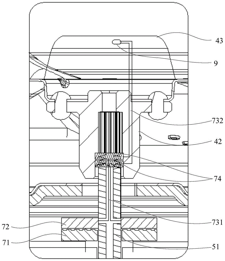
图4是图3中A的局部结构示意图二。FIG. 4 is a second partial structural schematic diagram of A in FIG. 3 .
附图中:1-外筒;3-内筒;4-波轮机构;41-波轮盘;42-轴套;43-波轮盖;5-驱动机构;51-输出轴;52-驱动电机;53-减速器;7-发电装置;71-磁体;72-线圈;721-气隙;731-第一导线;732-第二导线;74-导电轴承;9-用电装置。In the drawings: 1-outer cylinder; 3-inner cylinder; 4-pulsator mechanism; 41-pulsator disc; 42-shaft sleeve; 43-pulsator cover; 5-drive mechanism; 51-output shaft; 52-drive Motor; 53-reducer; 7-generating device; 71-magnet; 72-coil; 721-air gap; 731-first wire; 732-second wire; 74-conductive bearing; 9-electricity device.
具体实施方式Detailed ways
首先,本领域技术人员应当理解的是,这些实施方式仅仅用于解释本发明的技术原理,并非旨在限制本发明的保护范围。本领域技术人员可以根据需要对其作出调整,以便适应具体的应用场合。First of all, those skilled in the art should understand that these embodiments are only used to explain the technical principle of the present invention, and are not intended to limit the protection scope of the present invention. Those skilled in the art can adjust it as needed to adapt to specific applications.
其次,需要说明的是,在本发明的描述中,术语“内”、“外”、“顶”、“底”等指示的方向或位置关系的术语是基于附图所示的方向或位置关系,这仅仅是为了便于描述,而不是指示或暗示所述装置或构件必须具有特定的方位、以特定的方位构造和操作,因此不能理解为对本发明的限制。Secondly, it should be noted that, in the description of the present invention, the terms "inside", "outside", "top", "bottom", etc. indicate the direction or positional relationship based on the direction or positional relationship shown in the accompanying drawings , which is only for the convenience of description, rather than indicating or implying that the device or component must have a specific orientation, be constructed and operated in a specific orientation, and therefore should not be construed as a limitation on the present invention.
此外,还需要说明的是,在本发明的描述中,除非另有明确的规定和限定,术语“相连”、“连接”应做广义理解,例如,可以是固定连接,也可以是可拆卸连接,或一体地连接;可以是机械连接,也可以是电连接;可以是直接相连,也可以通过中间媒介间接相连,可以是两个构件内部的连通。对于本领域技术人员而言,可根据具体情况理解上述术语在本发明中的具体含义。In addition, it should also be noted that, in the description of the present invention, unless otherwise expressly specified and limited, the terms "connected" and "connected" should be understood in a broad sense, for example, it may be a fixed connection or a detachable connection , or integrally connected; it can be a mechanical connection or an electrical connection; it can be a direct connection or an indirect connection through an intermediate medium, and it can be the internal communication of the two components. For those skilled in the art, the specific meanings of the above terms in the present invention can be understood according to specific situations.
下面阐述本发明实施例的洗衣机的优选技术方案。The preferred technical solutions of the washing machine according to the embodiment of the present invention are described below.
首先参阅图1至图4。Refer first to FIGS. 1 to 4 .
如图1所示,本发明的洗衣机包括外筒1、内筒3、驱动机构5、发电装置7及用电装置9。此外,洗衣机一般还包括有通用的箱体及控制盘座。其中,为便于描述,本实施例及下述实施例以洗衣机支撑在地面上的一端(或者朝向地面的一端)为底端,与底端相对的一端为洗衣机的顶端。As shown in FIG. 1 , the washing machine of the present invention includes an
洗衣机的箱体可呈长方体状,箱体的顶端可设置有开口。箱体中设置有外筒1;内筒3穿过外筒1顶端开设的开口安装到外筒1内并可相对于外筒1旋转,内筒3的顶端设置有可供投放衣物的开口。其中,内筒3一般与外筒1同轴设置;内筒3可沿二者的中轴线旋转。容易理解,当洗衣机为滚筒式洗衣机时,内筒3的旋转轴可以水平设置或者与水平面之间具有一锐角,也即内筒3的旋转轴可从内筒3的后端水平或者稍微向上倾斜的延伸到前端,明显的,内筒3的旋转轴倾斜于水平面设置有助于取放衣物;当洗衣机为波轮式洗衣机时,内筒3的旋转轴竖直设置,也即内筒3的旋转轴可从内筒3的底端竖直延伸到顶端。The box body of the washing machine can be in the shape of a cuboid, and the top of the box body can be provided with an opening. The box body is provided with an
箱体的开口处设置有控制盘座,控制盘座中设置有用于控制洗衣机工作状态的主电路板,且控制盘座上设置有可开闭内筒3开口的盖体。其中,控制盘座设置有功能键,功能键可与主电路板电连接,以使用户可通过功能键调整洗衣机的工作状态;功能键包括如下至少一种:按键、旋钮、触摸键;控制盘座或者盖体上还可以设置有显示区,显示区用于显示洗衣机的工作状态信息(包括但不限于工作时长和剩余时长等)。The opening of the box body is provided with a control panel seat, the control panel seat is provided with a main circuit board for controlling the working state of the washing machine, and a cover body that can open and close the opening of the
对于滚筒式洗衣机而言,外筒1与箱体之间设置有驱动机构,驱动机构与主电路板电连接,以通过主电路板控制驱动机构带动内筒转动以实现对衣物的清洁、甩干。For the drum-type washing machine, a driving mechanism is provided between the
对于波轮式洗衣机而言,内筒3的底端还设置有波轮机构4,应当理解,波轮机构4位于内筒3的内部。与滚筒式洗衣机类似,波轮式洗衣机的外筒1与箱体之间也设置有驱动机构5,驱动机构5与主电路板电连接,以通过主电路板控制驱动电机52带动波轮机构4转动以实现对衣物的清洁,同时还能够通过主电路板控制驱动机构5带动内筒3转动以实现对衣物的清洁、甩干。For the pulsator type washing machine, the bottom end of the
当然,洗衣机的结构并不限于此,本实施例此处只是举例说明。对于洗衣机的结构及实现过程,本实施例未做说明的部分可采用本领域的常规选择。下面不妨以波轮式洗衣机为例,对本实施例的洗衣机的结构及实现过程进行举例说明。可以理解的是:当洗衣机为滚筒式等其它类型的洗衣机时,其实现过程可与本实施例的阐述类似。Of course, the structure of the washing machine is not limited to this, and the present embodiment is only exemplified here. For the structure and implementation process of the washing machine, the parts that are not described in this embodiment may adopt conventional choices in the art. The following may take a pulsator washing machine as an example to illustrate the structure and implementation process of the washing machine of this embodiment. It can be understood that when the washing machine is another type of washing machine such as a drum type, the implementation process thereof may be similar to that described in this embodiment.
在一些示例中,驱动机构5可以包括驱动电机52,驱动电机52的输出轴51与波轮机构4及内筒3连接;此时,驱动电机52的输出轴也即驱动机构5的输出轴51。在另一些示例中,驱动机构5包括驱动电机52及减速器53,减速器53设置在驱动电机52的输出端,减速器53的输出轴与波轮机构4及内筒3连接;此时,减速器53的输出轴也即驱动机构5的输出轴51。In some examples, the
如图1及图2所示,发电装置7可包括线圈72及磁体71。线圈72(也即转子)可设置在驱动机构5的输出轴51上;示例性地,线圈72可包括套设在驱动电机52输出轴51上的铁芯,铁芯上可绕设有单匝或者多匝导线。磁体71(也即定子)可设置在外筒1上,磁体71可在输出轴51的周围形成可供线圈72切割的磁场;其中,磁体71可以为永磁体71。As shown in FIGS. 1 and 2 , the
本示例中,驱动机构5带动波轮机构4或者内筒3转动的过程中,还可带动线圈72转动,如此,线圈72可在磁体71形成的磁场中切割磁感线,根据电磁感应原理,线圈72内部可产生电流,该电流可传输给设置在内筒3上、且与线圈72电连接的用电装置9,以为用电装置9提供电能。In this example, when the
在其中一可选实现方式中,线圈72可设置在输出轴51位于内筒3和外筒1之间的部分上;磁体71可设置在外筒1的内表面上。其中,磁体71可以包括外套设在线圈72外侧的环形磁铁;或者,磁体71可以包括设置在输出轴51相对两侧的第一磁铁及第二磁铁。此外,发电装置7还可以包括整流器,整流器可连接在线圈72与用电设备之间,整流器可用于将线圈72输出的交流电转换为直流电。当然,发电装置7的结构并不限于此,本实施例此处只是举例说明,只要其能够随着驱动机构5输出轴51的转动而产生可提供给用电装置9的电能即可。In one of the alternative implementations, the
在另一可选实现方式中,磁体71可以呈盘状,盘状的磁体71可套设在驱动机构5的输出轴51上,磁体71可固定在外筒1的内表面上,且磁体71形成磁场中具有沿输出轴51轴向的磁感线;线圈72套设在驱动机构5的输出轴51上,线圈72与输出轴51固定,以使线圈72与磁体71之间存在相对转动,且线圈72与磁体71之间具有一定的间距以形成气隙721。在本示例中,发电装置7的结构较简单,在保证发电效率的情况下,其较轻薄、体积较小、所占用空间较小,且对密封防水的要求较低。In another optional implementation manner, the
与发电装置7电连接的用电装置9可设置在内筒3中,具体可设置在内筒3的侧壁或者设置在波轮机构4等位置,由于线圈72设置在输出轴51上,如此,从发电装置7引出的导线在某些示例中就可以从驱动机构5的输出轴51中穿过并进入内筒3中以便与设置在内筒3上的用电装置9电连接。以用电装置9设置在内筒3的侧壁上为例,为了较好地保护导线及其与用电装置9的电连接,内筒3上与导线的走向相应的位置可以设置有保护壳,导线可设置在保护壳与内筒3侧壁围成的空间中;其中,保护壳上可供导线进入的入口端及靠近用电装置9的出口端,保护壳的入口端及出口端均有密封处理,如设置密封圈或者密封胶等密封件。The
其中,用电装置9可以包括温度传感器、重量传感器、液位传感器、发光灯、紫外灯、蜂鸣器等。Wherein, the
本实施例中,用电装置9可设置在内筒3侧壁的底端或者设置在内筒3的底端如波轮机构4等上,以缩短连接用电装置9及发电装置7的导线的走线路径。In this embodiment, the
本实施例提供的洗衣机,通过在驱动机构5的输出轴51处设置线圈72及磁体71,通过输出轴51带动线圈72转动且在磁体71形成的磁场中切割磁感线,以为设置在内筒3中的用电装置9提供电能。如此,连接在线圈72输出端的导线能够从驱动机构5的输出轴51穿过并与设置在内筒3中的用电装置9电连接,从而避免了导线由于内筒的旋转出现破损或者断裂,从而可以提高其使用寿命。当用电装置9安装于波轮机构上时,还可以缩短导线的走线路径。此外,通过利用驱动机构5自身的旋转运动产生电能提供给用电装置9,还有助于节能。In the washing machine provided in this embodiment, the
在其中一可选实施方式中,用电装置9包括安装在内筒3上的指示器,指示器用于向用户提供视觉或者听觉指示信号,以指示洗衣机的工作状态。In one of the optional embodiments, the
在一些示例中,指示器可以包括指示灯(例如白炽灯或者LED灯),指示灯用于向用户提供视觉指示信号。指示灯可以设置在内筒3的侧壁上,或者,指示灯设置在波轮机构4上,以便于简化连接指示灯与发电装置7的导线的走线路径。其中,指示灯可以为一个或者多个;当指示灯为多个时,多个指示灯亮起时的颜色可以包括至少两种,以提高用户体验。其中,指示灯可以在驱动机构5中的驱动电机的转速达到预设值时亮起,例如,指示灯可以在驱动电机的转速使得发电装置产生的电能满足指示灯的功率需求时亮起。In some examples, the indicator may include an indicator light (eg, incandescent or LED light) for providing a visual indication to the user. The indicator light can be arranged on the side wall of the
此外,指示器还可以包括控制器,控制器与指示灯电连接,以使得控制器分别控制指示灯的开闭时间、开闭频率。示例性地,在不同的工作阶段或者工作状态,控制器可控制相应的指示灯亮起相应的颜色。当然,如果有多个指示灯,则控制器可以控制这多个指示灯的工作状态,例如开闭时间、亮起的颜色等,以具有炫酷的灯光效果。In addition, the indicator may further include a controller, and the controller is electrically connected with the indicator light, so that the controller controls the on-off time and on-off frequency of the indicator light respectively. Exemplarily, in different working stages or working states, the controller can control the corresponding indicator lights to light up corresponding colors. Of course, if there are multiple indicator lights, the controller can control the working status of the multiple indicator lights, such as the opening and closing time, lighting color, etc., to have cool lighting effects.
在一些示例中,指示器还可以包括蜂鸣器,蜂鸣器用于向用户提供听觉指示信号。此外,指示器还可以包括控制器,控制器可与蜂鸣器电连接,控制器可用于蜂鸣器发出听觉提示信号的频率、时长等。In some examples, the indicator may also include a buzzer for providing an audible indication signal to the user. In addition, the indicator may further include a controller, the controller may be electrically connected with the buzzer, and the controller may be used for the frequency and duration of the buzzer to send out an audible prompt signal.
除此之外,用电装置还可以包括紫外灯,以实现对衣物的杀菌。In addition, the electrical device may further include an ultraviolet lamp to sterilize the clothes.
在其中一可选实施方式中,洗衣机的波轮机构4可以包括波轮盘41,波轮盘41的中部设置有沿输出轴51的轴向贯穿的通孔,通孔的底端设置有与驱动机构5的输出轴51连接的轴套42,通孔的顶端设置有与波轮盖43,且波轮盖43与波轮盘41密封配合,以免内筒3中的水从波轮盖43与波轮盘41之间泄漏。本示例中,波轮盘41上还设置有多个从中部向边缘延伸的筋条,在波轮盘41随驱动机构5往复转动时,波轮盘41将搅动其中的衣物在水中上下翻转,且通过与波轮盘41上设置的筋条的摩擦,并同时通过洗涤剂的作用,将衣物上的污物清洗干净。In one of the optional embodiments, the
如图3及图4所示,用电装置9可设置在波轮机构4上,以进一步简化连接用电装置9与发电装置7的导线的走线路径。当用电装置9为温度传感器等传感器时,用电装置9可以嵌设在波轮盖43上,且从用电装置9引出的导线可穿过波轮盖43并穿过驱动机构5的输出轴51与发电装置7电连接;其中,由于传感器可固定在波轮盖43上随波轮机构4一起旋转,也即用电装置9可与波轮机构4同步运动,因此,导线与波轮盖43上的第三过线孔之间可设置有密封圈、密封胶等密封件,以保证对用电装置9及发电装置7密封防水的可靠性。当用电装置9为指示灯时,指示灯可以设置在波轮盖43与波轮盘41围合成的空间内,如指示灯可以设置在波轮盘41中部的通孔中,以保证对用电装置9及发电装置7的防水的可靠性。容易理解,在这种示例下,波轮盖43可以是透明的或者半透明的,以便指示灯发出的光线可以从该波轮盖43射出。As shown in FIG. 3 and FIG. 4 , the
本示例中,连接用电装置9与发电装置7的导线可以包括第一导线731及第二导线732,第一导线731穿设在输出轴51上,第二导线732穿设在轴套42中。相应地,输出轴51可以为中空轴,且输出轴51可以设置又沿其径向延伸的第一过线孔,第一过线孔与输出轴51的中心孔连通,以使得从发电装置7引出的第一导线731从第一过线孔进入输出轴51的第一过线孔。在一些示例中,从输出轴51的中心孔穿出的导线可从轴套42的中心孔穿过并与用电装置9电连接;在另一些示例中,轴套42上可设置有沿其轴向延伸的第二过线孔,从用电装置9引出的第二导线732可穿设在第二过线孔中,相应地,输出轴51上还设置有第四过线孔,第一导线731可从第四过线孔穿出与第二导线732电连接。In this example, the wire connecting the
可选地,为了保证发电装置7、导线及用电装置9之间电连接的可靠性,输出轴51上安装有与第一导线731电连接的第一导电件,轴套42设置有与第二导线732电连接的第二导电件,第一导电件可相对于第二导电件转动并始终与第二导电件电连接。其中,第一导电件和第二导电件形成导电轴承74或导电滑环。如此,在波轮机构4与输出轴51之间具有相对转动时,发电装置7、导线及用电装置9之间也能可靠地电连接。Optionally, in order to ensure the reliability of the electrical connection between the
当然,用电装置9的设置位置并不限于波轮盖43的周围,用电装置9还可以设置在波轮盘41上,相应地,波轮盘41上需要设置可供连接用电装置9与发电装置7的导线穿过的第五过线孔,例如,用电装置9可以设置在波轮盘41上筋条处,第五过线孔可设置在筋条上。Of course, the setting position of the
在一些示例中,用电装置9还可以设置在线屑过滤器上,线屑过滤器包括过滤筛以及用于安装过滤筛的框体,用电装置9可设置在框体上。其中,线屑过滤器可以设置在内筒3的侧壁上,或者,线屑过滤器也可以设置在内筒3的底端,例如,将其设置在内筒3的排水口处。In some examples, the
在一些示例中,用电装置9还可以设置在平衡环上,当用电装置9为一个时,用电装置9的重心需与平衡环的重心重合;当用电装置9为多个时,多个用电装置9需均匀分布在平衡环上,以使得平衡环的重心不变,以保证平衡环的可靠性。其中,平衡环可以设置在内筒3的顶端。In some examples, the
可选地,外筒1的底壁向顶端凹陷形成有安装槽,磁体71和线圈72容纳在安装槽中。输出轴51穿设在安装槽中,且输出轴51与外筒1之间通过密封件密封,以保证对发电装置7密封防水的可靠性;其中,密封件可以为密封轴承等。Optionally, the bottom wall of the
磁体71外罩设有外壳,外壳固定在外筒1的内表面,输出轴51穿设在外壳中,且输出轴51与外壳之间通过密封件密封,以保证对发电装置7密封防水的可靠性;其中,密封件可以为密封轴承等。The outer cover of the
最后应说明的是:以上各实施例仅用以说明本发明的技术方案,而非对其限制;尽管参照前述各实施例对本发明进行了详细的说明,本领域的普通技术人员应当理解:其依然可以对前述各实施例所记载的技术方案进行修改,或者对其中部分或者全部技术特征进行等同替换;而这些修改或者替换,并不使相应技术方案的本质脱离本发明各实施例技术方案的范围。Finally, it should be noted that the above embodiments are only used to illustrate the technical solutions of the present invention, but not to limit them; although the present invention has been described in detail with reference to the foregoing embodiments, those of ordinary skill in the art should understand that: The technical solutions described in the foregoing embodiments can still be modified, or some or all of the technical features thereof can be equivalently replaced; and these modifications or replacements do not make the essence of the corresponding technical solutions deviate from the technical solutions of the embodiments of the present invention. scope.
Claims (10)
Priority Applications (1)
| Application Number | Priority Date | Filing Date | Title |
|---|---|---|---|
| CN201910171701.4A CN111663287B (en) | 2019-03-07 | 2019-03-07 | Washing machine |
Applications Claiming Priority (1)
| Application Number | Priority Date | Filing Date | Title |
|---|---|---|---|
| CN201910171701.4A CN111663287B (en) | 2019-03-07 | 2019-03-07 | Washing machine |
Publications (2)
| Publication Number | Publication Date |
|---|---|
| CN111663287A true CN111663287A (en) | 2020-09-15 |
| CN111663287B CN111663287B (en) | 2023-03-31 |
Family
ID=72381816
Family Applications (1)
| Application Number | Title | Priority Date | Filing Date |
|---|---|---|---|
| CN201910171701.4A Active CN111663287B (en) | 2019-03-07 | 2019-03-07 | Washing machine |
Country Status (1)
| Country | Link |
|---|---|
| CN (1) | CN111663287B (en) |
Cited By (2)
| Publication number | Priority date | Publication date | Assignee | Title |
|---|---|---|---|---|
| WO2021179912A1 (en) * | 2020-03-12 | 2021-09-16 | 青岛海尔洗衣机有限公司 | Laundry treatment apparatus |
| WO2021197111A1 (en) * | 2020-04-03 | 2021-10-07 | 青岛海尔洗衣机有限公司 | Laundry treatment apparatus |
Citations (12)
| Publication number | Priority date | Publication date | Assignee | Title |
|---|---|---|---|---|
| JP2003062388A (en) * | 2001-08-24 | 2003-03-04 | Nakagawa Electric Ind Co Ltd | Locking apparatus for tank lid |
| US20050194848A1 (en) * | 2004-03-02 | 2005-09-08 | Ahn In G | BLDC Motor |
| CN1779037A (en) * | 2004-11-19 | 2006-05-31 | 乐金电子(天津)电器有限公司 | Carriage structure of universal electric motor |
| CN101841583A (en) * | 2009-03-21 | 2010-09-22 | 鸿富锦精密工业(深圳)有限公司 | Input device and electronic device with same |
| JP2011244885A (en) * | 2010-05-24 | 2011-12-08 | Hitachi Appliances Inc | Washing machine |
| CN103630723A (en) * | 2013-11-25 | 2014-03-12 | 北京航空航天大学 | Rogowski coil sensing head suitable for Rogowski coil current sensor |
| JP2014068792A (en) * | 2012-09-28 | 2014-04-21 | Toshiba Corp | Drum type washing machine |
| CN103911795A (en) * | 2012-12-29 | 2014-07-09 | 海尔集团技术研发中心 | Washing machine and washing machine driving method |
| JP2014171563A (en) * | 2013-03-07 | 2014-09-22 | Panasonic Corp | Washing machine |
| WO2016119297A1 (en) * | 2015-01-27 | 2016-08-04 | 无锡小天鹅股份有限公司 | Impeller washing machine |
| CN106012406A (en) * | 2016-07-08 | 2016-10-12 | 中山东菱威力电器有限公司 | Washing machine with ultraviolet sterilization and disinfection function |
| CN207098768U (en) * | 2017-07-24 | 2018-03-13 | 博西华电器(江苏)有限公司 | Washing machine |
-
2019
- 2019-03-07 CN CN201910171701.4A patent/CN111663287B/en active Active
Patent Citations (12)
| Publication number | Priority date | Publication date | Assignee | Title |
|---|---|---|---|---|
| JP2003062388A (en) * | 2001-08-24 | 2003-03-04 | Nakagawa Electric Ind Co Ltd | Locking apparatus for tank lid |
| US20050194848A1 (en) * | 2004-03-02 | 2005-09-08 | Ahn In G | BLDC Motor |
| CN1779037A (en) * | 2004-11-19 | 2006-05-31 | 乐金电子(天津)电器有限公司 | Carriage structure of universal electric motor |
| CN101841583A (en) * | 2009-03-21 | 2010-09-22 | 鸿富锦精密工业(深圳)有限公司 | Input device and electronic device with same |
| JP2011244885A (en) * | 2010-05-24 | 2011-12-08 | Hitachi Appliances Inc | Washing machine |
| JP2014068792A (en) * | 2012-09-28 | 2014-04-21 | Toshiba Corp | Drum type washing machine |
| CN103911795A (en) * | 2012-12-29 | 2014-07-09 | 海尔集团技术研发中心 | Washing machine and washing machine driving method |
| JP2014171563A (en) * | 2013-03-07 | 2014-09-22 | Panasonic Corp | Washing machine |
| CN103630723A (en) * | 2013-11-25 | 2014-03-12 | 北京航空航天大学 | Rogowski coil sensing head suitable for Rogowski coil current sensor |
| WO2016119297A1 (en) * | 2015-01-27 | 2016-08-04 | 无锡小天鹅股份有限公司 | Impeller washing machine |
| CN106012406A (en) * | 2016-07-08 | 2016-10-12 | 中山东菱威力电器有限公司 | Washing machine with ultraviolet sterilization and disinfection function |
| CN207098768U (en) * | 2017-07-24 | 2018-03-13 | 博西华电器(江苏)有限公司 | Washing machine |
Cited By (2)
| Publication number | Priority date | Publication date | Assignee | Title |
|---|---|---|---|---|
| WO2021179912A1 (en) * | 2020-03-12 | 2021-09-16 | 青岛海尔洗衣机有限公司 | Laundry treatment apparatus |
| WO2021197111A1 (en) * | 2020-04-03 | 2021-10-07 | 青岛海尔洗衣机有限公司 | Laundry treatment apparatus |
Also Published As
| Publication number | Publication date |
|---|---|
| CN111663287B (en) | 2023-03-31 |
Similar Documents
| Publication | Publication Date | Title |
|---|---|---|
| CN102899847B (en) | There is the washing machine of motor | |
| CN112080901A (en) | laundry treatment equipment | |
| CN1924159B (en) | Washing machine | |
| CN111663287B (en) | Washing machine | |
| KR20180050095A (en) | Motor for washing machine and washing machine having the same | |
| KR100242321B1 (en) | Dc motor | |
| CN108696057A (en) | Motor and electrical equipment with the motor | |
| JP2012170681A (en) | Washing machine | |
| KR20070040901A (en) | Lighting control device of washing machine | |
| CN113389015B (en) | Clothes treating apparatus | |
| CN113417117B (en) | Clothes treating apparatus | |
| CN112709039A (en) | Drum washing machine | |
| CN107723992B (en) | A direct drive washing device | |
| CN208293264U (en) | A kind of magnetic suspension washing machine | |
| CN113337993B (en) | Clothes processing equipment | |
| WO2021143646A1 (en) | Clothing treatment device | |
| CN113622156A (en) | drum washing machine | |
| JP2009056113A (en) | Washing machine | |
| KR101934290B1 (en) | Washing machine | |
| WO2021223613A1 (en) | Control method for washing machine | |
| CN205368773U (en) | Door body area shows washing machine of function | |
| CN223103291U (en) | Clothes processing equipment | |
| CN105529873B (en) | Permanent magnet rotary electric machine and washing machine | |
| CN113493998A (en) | Clothes treating apparatus | |
| CN116180394A (en) | Clothes processing equipment |
Legal Events
| Date | Code | Title | Description |
|---|---|---|---|
| PB01 | Publication | ||
| PB01 | Publication | ||
| SE01 | Entry into force of request for substantive examination | ||
| SE01 | Entry into force of request for substantive examination | ||
| CB02 | Change of applicant information |
Address after: 266101 Haier Industrial Park, 1 Haier Road, hi tech park, Laoshan District, Shandong, Qingdao Applicant after: QINGDAO HAIER WASHING MACHINE Co.,Ltd. Applicant after: Haier Smart Home Co., Ltd. Address before: 266101 Haier Industrial Park, 1 Haier Road, hi tech park, Laoshan District, Shandong, Qingdao Applicant before: QINGDAO HAIER WASHING MACHINE Co.,Ltd. Applicant before: QINGDAO HAIER JOINT STOCK Co.,Ltd. |
|
| CB02 | Change of applicant information | ||
| GR01 | Patent grant | ||
| GR01 | Patent grant |