CN111663807A - A shelter with an air interlayer in the bulkhead - Google Patents
A shelter with an air interlayer in the bulkhead Download PDFInfo
- Publication number
- CN111663807A CN111663807A CN202010541902.1A CN202010541902A CN111663807A CN 111663807 A CN111663807 A CN 111663807A CN 202010541902 A CN202010541902 A CN 202010541902A CN 111663807 A CN111663807 A CN 111663807A
- Authority
- CN
- China
- Prior art keywords
- air
- wall
- air guide
- guide pipe
- layer
- Prior art date
- Legal status (The legal status is an assumption and is not a legal conclusion. Google has not performed a legal analysis and makes no representation as to the accuracy of the status listed.)
- Granted
Links
Images


Classifications
-
- E—FIXED CONSTRUCTIONS
- E04—BUILDING
- E04H—BUILDINGS OR LIKE STRUCTURES FOR PARTICULAR PURPOSES; SWIMMING OR SPLASH BATHS OR POOLS; MASTS; FENCING; TENTS OR CANOPIES, IN GENERAL
- E04H1/00—Buildings or groups of buildings for dwelling or office purposes; General layout, e.g. modular co-ordination or staggered storeys
- E04H1/12—Small buildings or other erections for limited occupation, erected in the open air or arranged in buildings, e.g. kiosks, waiting shelters for bus stops or for filling stations, roofs for railway platforms, watchmen's huts or dressing cubicles
- E04H1/1205—Small buildings erected in the open air
-
- E—FIXED CONSTRUCTIONS
- E04—BUILDING
- E04B—GENERAL BUILDING CONSTRUCTIONS; WALLS, e.g. PARTITIONS; ROOFS; FLOORS; CEILINGS; INSULATION OR OTHER PROTECTION OF BUILDINGS
- E04B1/00—Constructions in general; Structures which are not restricted either to walls, e.g. partitions, or floors or ceilings or roofs
- E04B1/62—Insulation or other protection; Elements or use of specified material therefor
- E04B1/74—Heat, sound or noise insulation, absorption, or reflection; Other building methods affording favourable thermal or acoustical conditions, e.g. accumulating of heat within walls
- E04B1/76—Heat, sound or noise insulation, absorption, or reflection; Other building methods affording favourable thermal or acoustical conditions, e.g. accumulating of heat within walls specifically with respect to heat only
- E04B1/7608—Heat, sound or noise insulation, absorption, or reflection; Other building methods affording favourable thermal or acoustical conditions, e.g. accumulating of heat within walls specifically with respect to heat only comprising a prefabricated insulating layer, disposed between two other layers or panels
- E04B1/7612—Heat, sound or noise insulation, absorption, or reflection; Other building methods affording favourable thermal or acoustical conditions, e.g. accumulating of heat within walls specifically with respect to heat only comprising a prefabricated insulating layer, disposed between two other layers or panels in combination with an air space
Landscapes
- Engineering & Computer Science (AREA)
- Architecture (AREA)
- Civil Engineering (AREA)
- Structural Engineering (AREA)
- Physics & Mathematics (AREA)
- Acoustics & Sound (AREA)
- Electromagnetism (AREA)
- Body Structure For Vehicles (AREA)
- Air-Conditioning For Vehicles (AREA)
Abstract
本发明一种舱壁中带有空气夹流层的方舱,属于散热设计领域;包括舱体骨架、舱体层板和进风通道组合,所述舱体层板包括内蒙皮层、隔热层、隔板层、空气夹流层、外蒙皮层,6个舱体层板分别固定于舱体骨架的6个空间面内;空气夹流层通过夹流层骨架固定于所述隔热层和外蒙皮层之间;所述夹流层骨架通过所述舱体连接角件固定于所述舱体骨架外侧,其侧壁上开有若干通孔作为骨架进风口和骨架出风口,与所述空气夹流层连通,用于实现空气在空气夹流层内的流动;所述进风通道组合通过风机向舱体层板内的空气夹流层排送气体。本发明通过流动的空气将外部太阳辐射到方舱表面的热量即时带走,避免热量累积在舱壁与舱顶板的隔热层中造成的舱内环境温度升高。
The invention discloses a shelter with an air interlayer in the bulkhead, belonging to the field of heat dissipation design; comprising a cabin frame, a cabin laminate and a combination of an air inlet channel, the cabin laminate comprising an inner skin layer, a heat insulation layer , partition layer, air sandwich layer, outer skin layer, 6 cabin body layers are respectively fixed in the 6 space planes of the cabin body frame; the air sandwich layer is fixed to the heat insulation layer and the Between the outer skin layers; the interlayer frame is fixed on the outside of the cabin frame through the cabin connecting corner pieces, and a number of through holes are opened on the side wall as the frame air inlet and the frame air outlet, which are connected with the frame. The air interlayer is connected to realize the flow of air in the air interlayer; the air inlet channel combination discharges gas to the air interlayer in the cabin laminate through the fan. The present invention immediately takes away the heat radiated by the external sun to the surface of the shelter through the flowing air, so as to avoid the increase of the ambient temperature in the cabin caused by the accumulation of heat in the thermal insulation layer of the bulkhead and the cabin roof.
Description
技术领域technical field
本发明属于散热设计领域,具体涉及一种舱壁中带有空气夹流层的方舱,通过改变方舱的舱壁结构减少外部热辐射能量向舱内传递。The invention belongs to the field of heat dissipation design, and in particular relates to a shelter with an air interlayer in the bulkhead, which reduces the transfer of external thermal radiation energy into the cabin by changing the bulkhead structure of the shelter.
背景技术Background technique
方舱可称作为能够整体移动、具有防护性的“房子”,大量使用在指挥系统、通信、医疗、后勤保障等领域,使用环境多为野外环境。为了隔热,通常在方舱的六个壁板(顶板、前壁、右壁、左壁、后壁、底板)中填充隔热材料。但是当方舱整体长时间暴露在高强度太阳辐射(尤其炎热的夏天或沙漠地带)环境中,舱壁中的隔热材料会累积大量的热量,通过热传导的方式将热量传递到方舱内部空间,造成舱内环境温度升高,即使在方舱内部安装了空调,环境温度也无法达到舒适的程度,严重的影响舱内工作人员身体健康。而且在野外环境中使用的方舱通常采用自带供电设备供电,单一的采用增大空调制冷量的方式降低舱内环境温度,会造成供电设备所需能源如燃油、蓄电池电量等快速消耗。Fangcang can be called a "house" that can move as a whole and has protective properties. It is widely used in command systems, communications, medical care, logistics support and other fields, and the use environment is mostly in the wild. In order to insulate the shelter, the six panels (top, front, right, left, rear, bottom) of the shelter are usually filled with insulating material. However, when the entire shelter is exposed to high-intensity solar radiation for a long time (especially in hot summer or desert areas), the thermal insulation material in the bulkhead will accumulate a lot of heat, and the heat will be transferred to the interior space of the shelter through heat conduction. This will cause the ambient temperature in the cabin to rise. Even if an air conditioner is installed inside the cabin, the ambient temperature cannot reach a comfortable level, which will seriously affect the health of the cabin staff. Moreover, the shelters used in the field environment are usually powered by their own power supply equipment. The single method of increasing the cooling capacity of the air conditioner to reduce the ambient temperature in the cabin will cause rapid consumption of the energy required by the power supply equipment, such as fuel and battery power.
专利CN201620903805公开一种方舱保温板,通过外保温层、内保温层、支撑框组成密闭腔室,减少热传递,但外保温层、内保温层在长时间太阳辐射热中累积大量热量传递到舱内。专利201911155707.9公开了一种特种车厢或方舱隔热保温材料及结构,通过耐高温隔热层中的高反射层、高热阻层与低导热保温层中的高反射层、高热阻层组成的多层结构减少热传递,但该多层结构直接与太阳辐射接触,在长时间、高强度太阳辐射环境下仍然会导致多层结构累积大量热量传递到舱内。Patent CN201620903805 discloses a shelter insulation board. A closed chamber is formed by an outer insulation layer, an inner insulation layer and a support frame to reduce heat transfer, but the outer insulation layer and the inner insulation layer accumulate a large amount of heat in the long-term solar radiation heat and transfer to inside the cabin. Patent 201911155707.9 discloses a special car or shelter thermal insulation material and structure, which is composed of a high reflection layer and a high thermal resistance layer in the high temperature resistant thermal insulation layer and a high reflection layer and a high thermal resistance layer in the low thermal conductivity thermal insulation layer. The layered structure reduces heat transfer, but the multi-layered structure is in direct contact with solar radiation, which will still cause the multi-layered structure to accumulate a large amount of heat and transfer to the cabin in a long-term, high-intensity solar radiation environment.
发明内容SUMMARY OF THE INVENTION
要解决的技术问题:Technical problem to be solved:
为了避免现有技术的不足之处,本发明提出一种舱壁中带有空气夹流层的方舱,该方舱包含空气夹流层与隔热层。空气夹流层位于隔热层外部,当太阳辐射照射到舱壁时,热量被空气夹流层空中流动的空气即时带走,通过出风口排到大气中,避免太阳辐射直接照射隔热层造成的热量累积,舱内环境温度升高的现象。In order to avoid the deficiencies of the prior art, the present invention proposes a shelter with an air interlayer in the bulkhead, and the shelter includes an air interlayer and a thermal insulation layer. The air interlayer is located outside the insulation layer. When the solar radiation irradiates the bulkhead, the heat is immediately taken away by the air flowing in the air interlayer, and is discharged into the atmosphere through the air outlet to avoid the direct exposure of the solar radiation to the insulation layer. The phenomenon that the heat accumulation in the cabin increases the ambient temperature in the cabin.
本发明的技术方案是:一种舱壁中带有空气夹流层的方舱,包括舱体骨架和舱体层板,所述舱体骨架为长方体框架结构,其顶角处均通过舱体连接角件固定连接;所述舱体层板包括内蒙皮层、隔热层和外蒙皮层,6个舱体层板分别固定于所述舱体骨架的6个空间面内;其特征在于:还包括设置于舱体层板内的空气夹流层和设置于方舱前壁上部的进风通道组合;The technical scheme of the present invention is: a square cabin with an air interlayer in the bulkhead, comprising a cabin frame and a cabin laminate, the cabin frame is a cuboid frame structure, and the top corners of the cabin pass through the cabin The connecting corner pieces are fixedly connected; the cabin layer plate includes an inner skin layer, a heat insulation layer and an outer skin layer, and the 6 cabin body layers are respectively fixed in the 6 space planes of the cabin body frame; it is characterized in that: It includes an air interlayer set in the cabin laminate and an air inlet channel set on the upper part of the front wall of the shelter;
所述空气夹流层通过夹流层骨架固定于所述隔热层和外蒙皮层之间,并与所述隔热层之间设置有隔板层;所述夹流层骨架通过所述舱体连接角件固定于所述舱体骨架外侧,其侧壁上开有若干通孔作为夹流层骨架进风口和夹流层骨架出风口,与所述空气夹流层连通,用于实现空气在空气夹流层内的流动;The air sandwich layer is fixed between the heat insulation layer and the outer skin layer through the sandwich layer frame, and a partition layer is arranged between the heat insulation layer; the sandwich layer frame passes through the cabin The body connecting corner piece is fixed on the outside of the cabin frame, and its side walls are provided with a number of through holes as the air inlet of the interlayer frame and the air outlet of the interlayer frame, which are communicated with the air interlayer to realize the air flow in the air interlayer;
所述进风通道组合包括外壳和两个风机,其外壳与方舱前壁的连接面上设置有若干前壁进风口,其底面两端均开有与风机连接的进风口,用于向舱体层板内的空气夹流层排送气体。The air inlet channel combination includes an outer casing and two fans. The connection surface between the outer casing and the front wall of the square cabin is provided with several front wall air inlets, and both ends of the bottom surface are provided with air inlets connected to the fans for supplying air to the cabin. The air-interlayer within the bulk laminate exhausts the gas.
本发明的进一步技术方案是:所述舱体连接角件为台阶式结构,包括正方体结构的角件台阶和垂直固定于其相邻的三个面上的三个阶梯方轴,所述阶梯方轴固定于角件台阶的一端为夹流层台阶,用于固定连接所述夹流层骨架,另一端为舱体骨架台阶,用于固定连接所述舱体骨架。A further technical solution of the present invention is: the cabin connecting corner piece is a stepped structure, including a corner piece step of a cube structure and three stepped square shafts vertically fixed on three adjacent surfaces thereof. One end of the shaft fixed to the step of the corner piece is an interlayer step, which is used for fixedly connecting the interlayer frame, and the other end is a cabin frame step, which is used for fixing and connecting the cabin frame.
本发明的进一步技术方案是:所述内蒙皮和隔板层材料均为2.5mm厚的铝板。A further technical solution of the present invention is: the materials of the inner skin and the partition layer are both aluminum plates with a thickness of 2.5 mm.
本发明的进一步技术方案是:所述隔热层包括外层、中层、内层三层隔热材料填充层,每层厚度为15mm。A further technical solution of the present invention is that: the thermal insulation layer comprises three layers of thermal insulation material filling layers, an outer layer, a middle layer and an inner layer, and the thickness of each layer is 15 mm.
本发明的进一步技术方案是:所述夹流层骨架由12根梁组成,分别为:左前立角梁、右前立角梁、右后立角梁、左后立角梁、左上长角梁、右上长角梁、右下长梁、左下长梁、前上横角梁、后上横角梁、前下横梁以及后下横梁,其中右下长梁与左下长梁结构尺寸相同,前下横梁与后下横梁结构尺寸相同,通过螺钉将所述12根梁固定连接于所述舱体骨架的8个所述舱体连接角件上,搭接成长方体框架包裹在隔板层的12条棱边上;使得所述长方体框架的上部、前侧、右侧、左侧与后侧分别为顶板夹流层框架、前壁夹流层框架、右壁夹流层框架、左壁夹流层框架、后壁夹流层框架;The further technical scheme of the present invention is: the interlayer frame is composed of 12 beams, which are: left front vertical beam, right front vertical beam, right rear vertical beam, left rear vertical beam, left upper long corner beam, The upper right long beam, the lower right long beam, the lower left long beam, the front upper horizontal beam, the rear upper horizontal beam, the front lower beam and the rear lower beam, of which the lower right long beam and the lower left long beam have the same structural dimensions, and the front lower beam The structure size is the same as that of the rear lower beam, the 12 beams are fixedly connected to the 8 cabin connecting corner pieces of the cabin frame by screws, and the cuboid frame is overlapped and wrapped around the 12 edges of the partition layer. On the side; make the upper part, front side, right side, left side and rear side of the cuboid frame respectively be the top plate interlayer frame, the front wall interlayer frame, the right wall interlayer frame, and the left wall interlayer frame , the rear wall interlayer frame;
所述前上横角梁、后上横角梁、左上长角梁与右上长角梁位于顶部,所述前上横角梁的横截面为等边L型,其一侧壁面上沿长度方向均布有多个腰子型顶板进风口,其两端的缺口分别作为后壁右侧进风口与后壁左侧进风口;所述后上横角梁的横截面为等边L型,其一侧壁面上沿长度方向均布有多个腰子型顶板出风口,其两端的缺口分别作为后壁左侧导风口与后壁右侧导风口;所述左上长角梁与右上长角梁结构形式相同,横截面为等边L型;The front upper horizontal angle beam, the rear upper horizontal angle beam, the upper left long angle beam and the upper right long angle beam are located at the top. There are a plurality of waist-shaped roof air inlets evenly distributed, and the gaps at both ends are respectively used as the air inlet on the right side of the rear wall and the air inlet on the left side of the rear wall; There are a plurality of waist-shaped roof air outlets evenly distributed on the wall along the length direction, and the gaps at both ends are respectively used as the left air guide of the rear wall and the right air guide of the rear wall; the upper left long angle beam and the right upper long angle beam have the same structural form , the cross section is an equilateral L-shape;
所述右下长梁、左下长梁、前下横梁与后下横梁位于底部,所述右下长梁的横截面为矩形,沿一侧壁的长度方向均布有多个腰子型右壁出风口;所述左下长梁的横截面为矩形,沿一侧壁的长度方向均布有多个腰子型左壁出风口;所述前下横梁的横截面为矩形,沿一侧壁的长度方向均布有多个腰子型前壁出风口;所述后下横梁的横截面为矩形,沿一侧壁的长度方向均布有多个腰子型后壁出风口;The right lower long beam, the left lower long beam, the front lower beam and the rear lower beam are located at the bottom. Air outlet; the cross section of the lower left long beam is rectangular, and a plurality of waist-shaped left wall air outlets are evenly distributed along the length direction of one side wall; the cross section of the front lower beam is rectangular, along the length direction of one side wall A plurality of waist-shaped front wall air outlets are evenly distributed; the cross section of the rear lower beam is rectangular, and a plurality of waist-shaped rear wall air outlets are evenly distributed along the length direction of one side wall;
所述左前立角梁、右前立角梁、右后立角梁与左后立角梁作为所述长方体框架的侧棱,所述右前立角梁的横截面为等边L型,其一端设置有缺口作为右壁进风口;所述左前立角梁的横截面为等边L型,其一端设置有缺口作为右壁进风口;所述右后立角梁与左后立角梁结构形式相同,横截面为等边L型。The left front vertical angle beam, the right front vertical angle beam, the right rear vertical angle beam and the left rear vertical angle beam are used as the side edges of the cuboid frame. There is a gap as the air inlet of the right wall; the cross section of the left front vertical angle beam is an equilateral L shape, and one end of the gap is provided with a gap as the air inlet of the right wall; the right rear vertical angle beam and the left rear vertical angle beam have the same structural form , the cross section is an equilateral L shape.
本发明的进一步技术方案是:所述空气夹流层内设置有导风层,方舱的导风层包括顶板导风层、前壁导风层、右壁导风层、左壁导风层、后壁导风层;A further technical solution of the present invention is: an air guide layer is arranged in the air interflow layer, and the air guide layer of the shelter includes a roof air guide layer, a front wall air guide layer, a right wall air guide layer, and a left wall air guide layer , the rear wall air guide layer;
所述的顶板导风层由左侧导风槽、右侧导风槽、多个顶板导风板组成,左侧风槽与右侧风槽平行设置于顶板导风层的两侧,其截面均为U型;多个L型顶板导风板平行并均布于所述左侧风槽与右侧风槽之间,形成的多个顶板导风带与所述前上横角梁的多个顶板进风口、后上横角梁的多个顶板出风口对应,形成风道;所述右侧风槽与前上横角梁的后壁右侧进风口、后上横角梁的后壁右侧导风口对应,形成后壁右侧导风通道;所述左侧风槽与前上横角梁的后壁左侧进风口、后上横角梁的后壁左侧导风口对应,形成后壁左侧导风通道;The top air guide layer is composed of a left air guide groove, a right air guide groove and a plurality of top air guide plates. The left air groove and the right air groove are arranged in parallel on both sides of the top air guide layer. All are U-shaped; a plurality of L-shaped roof air guide plates are parallel and evenly distributed between the left air groove and the right air groove, forming a plurality of roof air guide belts and a plurality of the front upper horizontal angle beams. The air inlets of the top plate and the air outlets of the top plate of the rear upper horizontal angle beam correspond to form an air duct; the right air groove is connected to the right air inlet of the rear wall of the front upper horizontal corner beam and the rear wall of the rear upper horizontal corner beam. The air guide on the right side corresponds to the air guide channel on the right side of the rear wall; the air groove on the left corresponds to the air inlet on the left side of the rear wall of the front upper horizontal angle beam and the left air guide port on the rear wall of the rear upper horizontal angle beam. The air guide channel on the left side of the rear wall;
所述的前壁导风层由前壁风槽和多个前壁导风板组成,前壁风槽紧贴所述前上横角梁,其截面均为U型,在前壁风槽下侧面沿长度方向均布有多个U型的前壁风槽出风口;多个前壁导风板垂直设置于所述前壁风槽下部,并沿其长度方向均布,形成多个前壁导风带;所述前壁导风带与前壁风槽下的前壁风槽出风口、前下横梁上的前壁出风口一一对应,形成多个导风通道;The front wall air guide layer is composed of a front wall air groove and a plurality of front wall air guide plates. The front wall air groove is close to the front upper horizontal angle beam, and its cross-section is U-shaped, under the front wall air groove. A plurality of U-shaped front wall air trough air outlets are evenly distributed along the length direction on the side surface; a plurality of front wall air guide plates are vertically arranged at the lower part of the front wall air trough, and are evenly distributed along its length direction to form a plurality of front walls an air guide belt; the front wall air guide belt is in one-to-one correspondence with the air outlet of the front wall air groove under the front wall air groove and the front wall air outlet on the front lower beam to form a plurality of air guide channels;
所述右壁导风层、左壁导风层、后壁导风层的结构与所述前壁导风层结构相同。The structures of the right wall air guiding layer, the left wall air guiding layer and the rear wall air guiding layer are the same as those of the front wall air guiding layer.
本发明的进一步技术方案是:所述外蒙皮材料均为2mm厚的铝板。A further technical solution of the present invention is: the outer skin materials are all aluminum plates with a thickness of 2 mm.
本发明的进一步技术方案是:所述方舱的8个顶角处、外蒙皮层外侧固定有8个舱体包角件,所述舱体包角件通过螺栓穿过所述外蒙皮层与舱体连接角件连接。A further technical solution of the present invention is: 8 corner wrapping pieces of the cabin body are fixed at the 8 top corners of the shelter and outside the outer skin layer, and the corner wrapping pieces of the cabin body pass through the outer skin layer and the outer skin layer through bolts. Cabin connection corner piece connection.
本发明的进一步技术方案是:位于方舱前壁的外蒙皮开有多个腰子型前蒙皮顶板进风口与多个腰子型前壁进风口;位于方舱后壁的外蒙皮的上部开有多个腰子型后蒙皮顶板出风口。The further technical scheme of the present invention is: the outer skin located on the front wall of the shelter is provided with a plurality of waist-shaped front skin roof air inlets and a plurality of waist-shaped front wall air inlets; the upper part of the outer skin located on the rear wall of the shelter is provided There are multiple waist-shaped rear skin roof air outlets.
本发明的进一步技术方案是:所述进风通道组合为左右对称结构,其外壳内分为右部进风通道、中部进风通道、左部进风通道,中部进风通道通过风道组合隔板分为中部上层风道与中部下层风道;所述中部上层风道对应的进风道组合外壳上沿长度方向开有多个腰子型风道,组成顶板进风口,中部下层风道对应的进风道组合外壳上沿长度方向开有多个腰子型风道,组成前壁进风口;A further technical solution of the present invention is: the air inlet channel is combined into a left-right symmetrical structure, and the outer casing is divided into a right air inlet channel, a middle air inlet channel, and a left air inlet channel, and the middle air inlet channel is separated by the combination of air channels. The board is divided into an upper air duct in the middle and a lower air duct in the middle; the combined casing of the air inlet duct corresponding to the upper air duct in the middle is provided with a plurality of waist-shaped air ducts along the length direction to form the air inlet of the top plate. A plurality of waist-shaped air ducts are opened on the air inlet duct combined shell along the length direction to form the front wall air inlet;
所述的右部进风通道包含:右壁导风管,后壁导风管、顶板导风管、前壁导风管、右部导风管支撑架、右部分风板、右侧进风管以及铝合金壳体,右壁导风管、后壁导风管、顶板导风管、前壁导风管采用焊接方式固定在右部导风管支撑架上;右壁导风管下部为右壁导风管进风口,上部为右壁导风管出风口;后壁导风管下部后壁导风管进风口,上部为后壁导风管出风口;顶板导风管下部为顶板导风管进风口,上部为顶板导风管出风口;前壁导风管下部为前壁导风管进风口,上部为出风口前壁导风管;右侧进风管位于右部进风通道的下方且与右壁导风管的右壁导风管进风口、后壁导风管的后壁导风管进风口、顶板导风管的顶板导风管进风口、前壁导风管的前壁导风管进风口连通,右部分风板位于右侧进风管上部,向右壁导风管导风;右壁导风管的右壁导风管出风口与右壁夹流层框架的右前立角梁的右壁进风口对应,形成导风通道;后壁导风管的后壁导风管出风口顶板夹流层框架的前上横角梁的后壁右侧进风口对应,形成导风通道;顶板导风管的顶板导风管出风口与中部进风通道的中部上层风道连通,前壁导风管的出风口与中部进风通道的中部下层风道连通;The right air inlet channel includes: the right wall air duct, the rear wall air duct, the roof air duct, the front wall air duct, the right air duct support frame, the right part of the air plate, and the right air inlet. Pipe and aluminum alloy shell, the right wall air duct, rear wall air duct, roof air duct, front wall air duct are fixed on the right air duct support frame by welding; the lower part of the right wall air duct is The air inlet of the right wall air duct, the upper part is the air outlet of the right wall air duct; the lower part of the rear wall air duct is the air inlet of the rear wall air duct, and the upper part is the air outlet of the rear wall air duct; the lower part of the roof air duct is the roof guide The air duct air inlet, the upper part is the top plate air duct air outlet; the lower part of the front wall air duct is the front wall air duct air inlet, and the upper part is the front wall air duct of the air outlet; the right air inlet duct is located in the right air inlet channel Below and with the right wall air duct air inlet of the right wall air duct, the rear wall air duct air inlet of the rear wall air duct, the top plate air duct air inlet of the roof air duct, and the front wall air duct The air inlet of the front wall air duct is connected, and the right part of the air plate is located on the upper part of the right air inlet duct, and the right wall air duct guides the air; the right wall air duct of the right wall air duct is connected to the right wall interlayer frame The air inlet on the right wall of the right front vertical angle beam of the rear wall corresponds to the air inlet of the right wall to form an air guide channel; An air guide channel is formed; the air outlet of the top plate air guide pipe of the top plate air guide pipe is connected with the middle upper air channel of the middle air inlet channel, and the air outlet of the front wall air guide pipe is connected with the middle lower air channel of the middle air inlet channel;
所述的左部进风通道包含:左壁导风管,后壁导风管、顶板导风管、前壁导风管、左部导风管支撑架、左部分风板、左侧进风管以及铝合金壳体,左壁导风管、后壁导风管、顶板导风管、前壁导风管采用焊接方式固定在左部导风管支撑架上;左侧进风管位于左部进风通道的下方且与左壁导风管的左壁导风管进风口、后壁导风管的后壁导风管进风口、顶板导风管的顶板导风管进风口、前壁导风管的前壁导风管进风口连通;左部分风板位于左侧进风管上部,向左壁导风管导风;左壁导风管的左壁导风管出风口与左壁夹流层框架的左前立角梁的左壁进风口对应,形成导风通道;后壁导风管的后壁导风管出风口与顶板夹流层框架的前上横角梁的后壁左侧进风口对应,形成导风通道;顶板导风管的顶板导风管出风口与中部进风通道的中部上层风道连通,前壁导风管的出风口与中部进风通道的中部下层风道连通。The left air inlet channel includes: the left wall air duct, the rear wall air duct, the roof air duct, the front wall air duct, the left air duct support frame, the left part of the air plate, and the left air inlet. Pipe and aluminum alloy shell, the left wall air duct, rear wall air duct, roof air duct, front wall air duct are fixed on the left air duct support frame by welding; the left air inlet duct is located on the left The lower part of the air inlet channel and the left wall air duct air inlet of the left wall air duct, the rear wall air duct air inlet of the rear wall air duct, the top plate air duct air inlet of the roof air duct, the front wall air duct The air inlet of the air duct on the front wall of the air duct is connected; the left part of the air plate is located on the upper part of the left air inlet duct and guides the air to the left wall air duct; the left wall air duct of the left wall air duct is connected to the left wall. The left wall air inlet of the left front vertical angle beam of the interlayer frame corresponds to form an air guide channel; the air outlet of the rear wall air guide duct of the rear wall air guide duct and the rear wall left of the front upper cross angle beam of the top plate interlayer frame The side air inlets correspond to form an air guiding channel; the air outlet of the roof air guiding duct of the roof air guiding duct is connected with the middle upper air channel of the middle air inlet channel, and the air outlet of the front wall air guiding tube is connected with the middle lower air channel of the middle air inlet channel. Road connection.
有益效果beneficial effect
本发明的有益效果在于:本发明基于一种舱壁中带有空气夹流层的方舱,通过在方舱顶板、左壁、右壁、前壁、后壁的中设计空气夹流层,通过流动的空气,将外部太阳辐射到方舱表面的热量即时带走,避免热量累积在舱壁与舱顶板的隔热层中造成的舱内环境温度升高。本方面主要技术手段是阻止外部辐射的热量直接传递到舱内,因此针对外部热辐射较强的环境,如炎热的夏天或高温沙漠环境等,与常规方舱隔热方式相比,能够明显阻止舱内环境温度升高。The beneficial effects of the present invention are as follows: the present invention is based on a shelter with an air interlayer in the bulkhead, and by designing the air interlayer in the roof, left wall, right wall, front wall and rear wall of the shelter, Through the flowing air, the heat radiated by the external sun to the surface of the shelter is taken away immediately, avoiding the increase of the ambient temperature in the cabin caused by the accumulation of heat in the insulation layer of the bulkhead and the roof panel. The main technical means of this aspect is to prevent the heat from external radiation from being directly transferred to the cabin. Therefore, for environments with strong external heat radiation, such as hot summer or high-temperature desert environments, compared with conventional shelter insulation methods, it can significantly prevent The ambient temperature in the cabin increases.
附图说明Description of drawings
图1为本发明舱体骨架。Figure 1 is the skeleton of the cabin of the present invention.
图2为本发明顶板框架、右壁框架与前壁框架。Figure 2 shows the top plate frame, the right wall frame and the front wall frame of the present invention.
图3为本发明的左壁框架与后壁框架。FIG. 3 shows the left wall frame and the rear wall frame of the present invention.
图4为本发明的舱体连接角件。Fig. 4 is a cabin connecting corner piece of the present invention.
图5为本发明的顶板内蒙皮、前壁内蒙皮与右壁内蒙皮。FIG. 5 shows the inner skin of the top plate, the inner skin of the front wall and the inner skin of the right wall of the present invention.
图6为本发明的左壁内蒙皮、后壁内蒙皮与底板内蒙皮。FIG. 6 shows the inner skin of the left wall, the inner skin of the rear wall and the inner skin of the bottom plate of the present invention.
图7为本发明的前壁内蒙皮与后壁内蒙皮。FIG. 7 shows the inner skin of the front wall and the inner skin of the rear wall of the present invention.
图8为本发明的填充模块。Figure 8 is a filling module of the present invention.
图9为本发明的顶板、前壁与右壁填充层。Figure 9 shows the top plate, front wall and right wall filling layer of the present invention.
图10为本发明的右壁、后壁与底板填充层。Figure 10 shows the filling layers of the right wall, rear wall and bottom plate of the present invention.
图11为本发明的上隔板、前壁隔板与右壁隔板。Figure 11 shows the upper partition, the front wall partition and the right wall partition of the present invention.
图12为本发明的左壁隔板、后壁隔板与底板。Figure 12 shows the left wall partition, the rear wall partition and the bottom plate of the present invention.
图13为本发明的顶板夹流层框架、前壁夹流层框架与右壁夹流层框架。Figure 13 shows the top plate interlayer frame, the front wall interlayer frame and the right wall interlayer frame of the present invention.
图14为本发明的左壁夹流层框架与后壁夹流层框架。Figure 14 shows the left wall interlayer frame and the rear wall interlayer frame of the present invention.
图15为本发明的前上横角梁。Fig. 15 is the front upper cross angle beam of the present invention.
图16为本发明的后上横角梁。FIG. 16 is a rear upper cross angle beam of the present invention.
图17为本发明的右前立角梁。Fig. 17 is the right front vertical angle beam of the present invention.
图18为本发明的左前立角梁。Fig. 18 is the left front vertical angle beam of the present invention.
图19为本发明的右下长梁。Figure 19 shows the lower right long beam of the present invention.
图20为本发明的左下长梁。Figure 20 shows the lower left long beam of the present invention.
图21为本发明的前下横梁。Figure 21 shows the front lower cross member of the present invention.
图22为本发明的后下横梁。Figure 22 is a rear lower cross member of the present invention.
图23为本发明的夹流层右前视图。Figure 23 is a right front view of the interlayer of the present invention.
图24为本发明的夹流层左后视图。Figure 24 is a left rear view of the interlayer of the present invention.
图25为本发明的顶板导风层与前壁导风层。Figure 25 shows the top plate air guide layer and the front wall air guide layer of the present invention.
图26为本发明的前壁风槽。Fig. 26 is the front wall air groove of the present invention.
图27为本发明的右壁导风层。Fig. 27 is the air guide layer of the right wall of the present invention.
图28为本发明的右壁风槽。Figure 28 is the right wall air groove of the present invention.
图29为本发明的弧形导风板。Figure 29 is the arc-shaped wind deflector of the present invention.
图30为本发明的左壁导风层。Figure 30 is the left wall air guide layer of the present invention.
图31为本发明的左壁风槽。Figure 31 is the left wall air trough of the present invention.
图32为本发明的窗户下部导风板。Figure 32 shows the lower wind deflector of the window of the present invention.
图33为本发明的后壁导风层。Figure 33 is the rear wall air guide layer of the present invention.
图34为本发明的后壁风槽。Figure 34 shows the rear wall air duct of the present invention.
图35为本发明的外蒙皮右前视图。Figure 35 is a right front view of the outer skin of the present invention.
图36为本发明的外蒙皮左后视图。Figure 36 is a left rear view of the outer skin of the present invention.
图37为本发明的前部左上包角件。Figure 37 is the front upper left corner wrapping piece of the present invention.
图38为本发明的前部右上包角件。Figure 38 is the front upper right corner wrapping piece of the present invention.
图39为本发明的后部上包角件。Figure 39 is a rear corner wrap of the present invention.
图40为本发明的下部包角件。Figure 40 is a lower corner wrap of the present invention.
图41为本发明的前壁外蒙皮。Figure 41 is a front wall outer skin of the present invention.
图42为本发明的后壁外蒙皮。Figure 42 is a rear wall outer skin of the present invention.
图43为本发明的方舱安装进风道组合视图。Figure 43 is a combined view of the air inlet duct installed in the shelter of the present invention.
图44为本发明的进风道组合内部结构。Figure 44 shows the internal structure of the air inlet duct assembly of the present invention.
图45为本发明的右部进风通道。Figure 45 shows the right air inlet channel of the present invention.
图46为本发明的右壁导风管。Figure 46 shows the right wall air duct of the present invention.
图47为本发明的后壁导风管。Figure 47 shows the rear wall air duct of the present invention.
图48为本发明的顶板导风管。Fig. 48 is a top plate air duct of the present invention.
图49为本发明的前壁导风管。Figure 49 is a front wall air duct of the present invention.
图50为本发明的左部进风通道。Figure 50 shows the left air inlet channel of the present invention.
图51为本发明的左壁导风管。Figure 51 shows the left wall air duct of the present invention.
图52为本发明的右部进风通道空气流向图。Figure 52 is a diagram of the air flow direction of the right air inlet channel of the present invention.
图53为本发明的左部进风通道空气流向图。Fig. 53 is the air flow diagram of the left air inlet channel of the present invention.
图54为本发明的中部进风通道空气流向图。Fig. 54 is an air flow diagram of the central air inlet channel of the present invention.
图55为本发明的进风通道后部空气流向图。Fig. 55 is a flow diagram of the air at the rear of the air inlet channel of the present invention.
图56为本发明的顶板导风层空气流向图。Fig. 56 is a diagram showing the air flow direction of the roof air guide layer of the present invention.
图57为本发明的前壁导风层空气流向图。FIG. 57 is a diagram of the air flow direction of the front wall air guide layer of the present invention.
图58为本发明的右壁导风层空气流向图。Fig. 58 is a diagram showing the air flow direction of the air guide layer on the right wall of the present invention.
图59为本发明的左壁导风层空气流向图。Fig. 59 is the air flow diagram of the left wall air guide layer of the present invention.
图60为本发明的后壁导风层空气流向图。FIG. 60 is a diagram of the air flow direction of the rear wall air guide layer of the present invention.
附图标记说明:1.立梁 2.长梁 3.横梁 4.舱体连接角件 5.窗户框架 6.窗户支撑短梁 7.窗户支撑长梁 8.舱门框架 9.舱门支撑梁 10.孔口框架 11.信号孔口支撑短梁12.信号孔口支撑长梁 13顶板框架 14.右壁框架 15.前壁框架 16.左壁框架 17.后壁框架 18.底板框架 19.顶板加强横梁 20.底板加强横梁 21.顶板内蒙皮 22.前壁内蒙皮23.右壁内蒙皮 24.左壁内蒙皮 25.后壁内蒙皮 26.底板内蒙皮 27.顶板填充模块 28.前壁填充模块 29.舱门前部填充模块 30.舱门上部填充模块 31.舱门后部填充模块 32.信号孔口下部填充模块 33.信号孔口上部填充模块 34.信号孔门后部填充模块 35.前部填充模块、36.窗户上部填充模块、37.窗户下部填充模块 38.窗户后部填充模块 39.后壁填充模块 40.底板填充模块 41.上隔板 42.前壁隔板 43.右壁隔板 44.左壁隔板 45.后壁隔板 46.底板 47.左前立角梁 48.右前立角梁 49.右后立角梁 50.左后立角梁 51.左上长角梁 52.右上长角梁 53.右下长梁 54.左下长梁 55.前上横角梁 56.后上横角梁 57.前下横梁 58.后下横梁 59.顶板夹流层框架 60.前壁夹流层框架 61.右壁夹流层框架62.左壁夹流层框架 63.后壁夹流层框架 64.顶板导风层 65.前壁导风层 66.右壁导风层67.左壁导风层 68后壁导风层。69.左侧导风槽 70.右侧导风槽 71.顶板导风板 72.顶板导风带 73.前壁风槽 74.前壁导风板 75.前壁导风带 76.右壁导风带 77.舱门框架上部导风带 78.信号孔口上部导风带 79.右壁导风板 80.舱门框架上部导风板 81.信号孔口上部导风板 82.右壁风槽 83.弧形导风板 84.左壁导风带 85.窗户框架处导风带 86.左壁导风板 87窗户框架上部导风板 88窗户框架下部导风板 89.窗户框架下部分风板 90.左壁风槽 91.后壁导风带 92后壁导风板 93.后壁风槽 94.顶板外蒙皮 95.前壁外蒙皮96.右壁外蒙皮 97.左壁外蒙皮 98.后壁外蒙皮 99.前部右上包角件、100.前部左上包角件 101.后部上包角件 102.下部包角件 103.舱门 104.信号孔口盖板 105.窗户 106.进风通道组合 107.风机 108.右部进风通道 109.中部进风通道 110.左部进风通道 111.风道组合隔板 112.右壁导风管 113.后壁导风管 114.顶板导风管 115.前壁导风管 116.右部导风管支撑架 117.右侧分风板 118.右侧进风管 119.左壁导风管 120.左部导风管支撑架 121.左部分风板 122.左侧进风管;Description of reference numerals: 1.
a.包角件台阶 b.夹流层台阶 c.舱体骨架台阶 d.包角件连接孔 e.夹流层连接孔 f.舱体骨架连接孔 g.前壁内蒙皮与右壁内蒙皮翻边 h.填充模块的外层 i.填充模块的中层 j.填充模块的中层 k.后壁右侧进风口 l.后壁左侧进风口 m.顶板进风口 n.舱体连接角件连接孔 o.包角件连接孔 p.后壁左侧导风口 q.后壁右侧导风口 r.顶板出风口s.右壁进风口 t.左壁进风口 u.右壁出风口 v.左壁出风口 w.前壁出风口 x.后壁出风口y.前壁风槽出风口 z.右壁风槽出风口;a. Corner fitting step b. Sandwich layer step c. Cabin frame step d. Corner fitting connection hole e. Sandwich layer connection hole f. Cabin frame connection hole g. Front wall inner skin and right wall inner skin Flanging h. Outer layer of filling module i. Middle layer of filling module j. Middle layer of filling module k. Air inlet on the right side of the rear wall l. Air inlet on the left side of the rear wall m. Hole o. Corner fitting connection hole p. Air guide on the left side of the rear wall q. Air guide on the right side of the rear wall r. Air outlet on the top plate s. Air inlet on the right wall t. Air inlet on the left wall u. Air outlet on the right wall v. Left Wall outlet w. Front wall outlet x. Rear wall outlet y. Front wall air slot outlet z. Right wall air slot outlet;
a1.弧形导风板导风口 b1.左壁风槽出风口 c1.窗户框架处分风口 d1.后壁左侧导风口 e1.后壁右侧导风口 f1.后壁风槽出风口 g1.前部左上包角件顶板 h1.前部左上包角件前板 i1.前部左上包角件左侧板 j1.包角件左壁进风口 k1.包角件后壁左侧进风口 l1.吊装环 n1.包角件与夹流层骨架连接孔 m1.包角件与进风通道组合连接孔 o1.包角件与进风通道组合连接孔 p1.前部右上包角件顶板 q1.前部右上包角件前板 r1.前部右上包角件右侧板 s1.包角件右壁进风口 t1.包角件后壁右侧进风口 u1.后部上包角件顶板、v1.后部上包角件侧板 w1.下部包角件侧板 x1.前蒙皮顶板进风口 y1.前壁进风口z1.前蒙皮后壁右侧进风口;a1. Arc air deflector air guide b1. Left wall air trough air outlet c1. Window frame disposition air outlet d1. Rear wall left air guide e1. Rear wall right air guide f1. Rear wall air groove outlet g1. Front Top plate of the upper left corner part h1. Front plate of the upper left corner part of the front part i1. Left side plate of the front upper left corner part j1. Ring n1. The connection hole between the corner piece and the interlayer skeleton m1. The combined connection hole of the corner piece and the air inlet channel o1. The combined connection hole of the corner piece and the air inlet channel p1. The front upper right corner piece top plate q1. Front Right upper corner piece front panel r1. Front right upper right corner piece right side plate s1. Right wall air inlet t1 of corner piece. Right air inlet u1. Rear upper right corner piece top plate, v1. Rear Upper corner piece side plate w1. Lower corner piece side plate x1. Front skin top plate air inlet y1. Front wall air inlet z1. Front skin rear wall right air inlet;
a2.前蒙皮后壁左侧进风口 b2.前蒙皮右壁进风口 c2.前蒙皮左壁进风口 d2.后蒙皮顶板出风口 e2.风道组合顶板进风口 f2.风道组合前壁进风口 g2.右壁导风管进风口 h2.右壁导风管出风口 i2.后壁导风管进风口 j2.后壁导风管出风口 k2.顶板导风管进风口 l2.顶板导风管出风口 m2.前壁导风管进风口 n2.前壁导风管出风口 o2.左壁导风管进风口 p2.左壁导风管出风口;a2. The left air inlet of the rear wall of the front skin b2. The air inlet of the right wall of the front skin c2. The air inlet of the left wall of the front skin d2. The air outlet of the rear skin roof e2. The air inlet of the air duct combination roof f2. The air duct combination Front wall air inlet g2. Right wall air duct air inlet h2. Right wall air duct air outlet i2. Rear wall air duct air inlet j2. Rear wall air duct air outlet k2. Top plate air duct air inlet l2. Top plate air duct air outlet m2. Front wall air duct air inlet n2. Front wall air duct air outlet o2. Left wall air duct air inlet p2. Left wall air duct air outlet;
具体实施方式Detailed ways
下面通过参考附图描述的实施例是示例性的,旨在用于解释本发明,而不能理解为对本发明的限制。The embodiments described below with reference to the accompanying drawings are exemplary, and are intended to explain the present invention and should not be construed as limiting the present invention.
在本发明的描述中,需要理解的是,术语“中心”、“纵向”、“横向”、“长度”、“宽度”、“厚度”、“上”、“下”、“前”、“后”、“左”、“右”、“竖直”、“水平”、“顶”、“底”、“内”、“外”、“顺时针”、“逆时针”等指示的方位或位置关系为基于附图所示的方位或位置关系,仅是为了便于描述本发明和简化描述,而不是指示或暗示所指的装置或元件必须具有特定的方位、以特定的方位构造和操作,因此不能理解为对本发明的限制。In the description of the present invention, it should be understood that the terms "center", "longitudinal", "lateral", "length", "width", "thickness", "upper", "lower", "front", " rear, left, right, vertical, horizontal, top, bottom, inside, outside, clockwise, counterclockwise, etc., or The positional relationship is based on the orientation or positional relationship shown in the accompanying drawings, which is only for the convenience of describing the present invention and simplifying the description, rather than indicating or implying that the referred device or element must have a specific orientation, be constructed and operated in a specific orientation, Therefore, it should not be construed as a limitation of the present invention.
参阅图1、图2、图3,本发明的舱体骨架由4根立梁1、4根长梁2、4根横梁3以及8个舱体连接角件4搭接成立方体结构,立方体结构的上部、右部、前部、左部、后部、底分别对应:顶板框架13、右壁框架14、前壁框架15、左壁框架16、后壁框架17、底板框架18。立方体结构8个顶点部位分别采用舱体连接角件4连接,通过埋头螺钉将4根立梁1、4根长梁2、4根横梁3连接为整体结构。在顶板框架13内等间距的安装6根顶板加强横梁19,6根顶板加强横梁19焊接在顶板框架13的左右两边的长梁2上。在底板框架18内等间距的安装6根底板加强横梁20,6根底板加强横梁20焊接在底板框架18左右两边的长梁2上。在左壁框架16内安装窗户框架5,窗户框架5通过2根窗户支撑短梁6与左壁框架16上方的长梁2连接,通过2根窗户支撑长梁7与左壁框架16下方的长梁2连接,连接方式均为焊接。在右壁框架14内安装舱门框架8,舱门框架8上部通过2根舱门支撑梁9与右壁框架14上方的长梁2连接,舱门框架8下部与右壁框架14下方的长梁2连接,连接方式均为焊接。在右壁框架14内位于舱门框架8后方安装信号孔口框架10,信号孔口框架10通过2根信号孔口支撑长梁12与右壁框架14上方的长梁2连接,通过2根信号孔口支撑短梁11与右壁框架14下方的长梁2连接,连接方式均为焊接。4根立梁1、4根长梁2、4根横梁3、窗户支撑短梁6、窗户支撑长梁7、舱门支撑梁9、信号孔口支撑短梁11、信号孔口支撑长梁12、顶板加强横梁19、底板加强横梁20的材料为铝合金,截面为宽度50mm、高度50mm、壁厚5mm的U型结构。Referring to Fig. 1, Fig. 2, Fig. 3, the cabin frame of the present invention is lapped to form a cubic structure by 4
图4为本发明的舱体连接角件,舱体连接角件采用台阶式结构,包含1个包角件台阶a,3个夹流层台阶b,3个舱体骨架台阶c。3个夹流层台阶b与包角件台阶a固连并互相成90度夹角,3个舱体骨架台阶c与3个夹流层台阶b固连并互相成90度夹角。包角件台阶a上有3个规格为M12的包角件连接孔e,用于连接外包角与外蒙皮。3个夹流层台阶b均上有4个规格为M8的夹流层连接,用于连接夹流层层骨架。3个舱体骨架台阶c上均有2个规格为M8舱体骨架连接孔f,用于连接舱体骨架。Fig. 4 is a cabin connecting corner piece of the present invention. The cabin connecting corner piece adopts a stepped structure, including one corner wrapping step a, three interlayer steps b, and three cabin frame steps c. The three interlayer steps b are fixedly connected with the corner wrapping step a and form a 90-degree angle with each other, and the three cabin frame steps c are fixedly connected with the three interlayer steps b and form a 90-degree angle with each other. There are three M12 size connecting holes e on the corner piece step a, which are used to connect the outer corner and the outer skin. There are 4 interlayer connections of size M8 on each of the three interlayer steps b, which are used to connect the interlayer skeleton. There are two connecting holes f of M8 cabin frame on the three cabin frame steps c, which are used to connect the cabin frame.
参阅图1、图2、图3、图5、图6、图7。本发明的内蒙皮层由顶板内蒙皮21、前壁内蒙皮22、右壁内蒙皮23、左壁内蒙皮24、后壁内蒙皮25、底板内蒙皮26组成。6个内蒙皮材料均为2.5mm厚的铝板。顶板内蒙皮21与顶板框架13的2根长梁2与2根横梁3焊接。底板内蒙皮26与底板框架18的2根长梁2与2根横梁3焊接。左壁内蒙皮25与左壁框架16的2根立梁1焊接。右壁内蒙皮23与右壁框架14的2根立梁1焊接。前壁内蒙皮22与后壁内蒙皮25四周折起90度翻边g,翻边g高度为20mm,前壁内蒙皮22与后壁内蒙皮25分别位于前壁框架15与后壁框架17内侧,通过四周翻边g与顶板内蒙皮21、右壁内蒙皮23、左壁24内蒙皮、底板内蒙皮26焊接。Refer to Figure 1, Figure 2, Figure 3, Figure 5, Figure 6, Figure 7. The inner skin layer of the present invention is composed of a top plate
参阅图1、图2、图3、图5、图6、图8、图9、图10,本发明的隔热材料填充层由多个填充模块组成。每个填充模块分为外层h、中层i、内层j,每层厚度为15mm。在方舱顶板中7个大小均为2300mm×508mm顶板填充模块27嵌在顶板框架13的6根顶板加强横梁19中间,分别与顶板内蒙皮21粘接。在方舱右壁中包含6个填充模块:舱门前部填充模块29、舱门上部填充模块30、舱门后部填充模块31,信号孔口上部填充模块33、信号孔口下部填充模块32、信号孔门后部填充模块34对应的分别嵌在右壁框架14的舱门框架8的前部、上部、后部以及信号孔口框架10的上部、下部、后部,该6个填充模块与右壁内蒙皮23粘接。在方舱前壁中为1个前壁填充模块28,嵌在舱体前壁框架15内,粘接在前壁内蒙皮22上。在方舱左壁中,包含4个填充模块:窗户前部填充模块35、窗户上部填充模块36、窗户下部填充模块37与窗户后部填充模块38,分别嵌在舱体骨架的左壁框架16中的窗户框架5的前部、上部、下部、后部,该4个填充模块与左壁内蒙皮24粘接。在方舱后壁中为1个后壁填充模块39,嵌在后壁框架17内,粘接在后壁内蒙皮25上。在方舱底板中为7个尺寸为2300mm×508mm底板填充模块40嵌在底板框架18的6根底板加强横梁20中间,分别与底板内蒙皮26粘接。Referring to Figure 1, Figure 2, Figure 3, Figure 5, Figure 6, Figure 8, Figure 9, Figure 10, the insulating material filling layer of the present invention is composed of a plurality of filling modules. Each filling module is divided into an outer layer h, a middle layer i, and an inner layer j, and the thickness of each layer is 15mm. In the roof of the shelter, seven
参阅图2、图3、图11、图12,本发明的隔板层位于隔热层外侧,由上隔板41、前壁隔板42、右壁隔板43、左壁隔板44、后壁隔板45、底板46组成,材料均为2.5mm厚的铝板。通过焊接方式将上隔板41、前壁隔板42、右壁隔板43、左壁隔板44、后壁隔板45、底板46焊接于舱体骨架的顶板框架13、前壁框架14、右侧壁框架15、左侧壁框架16、后壁框架17、底板框架18外侧面。2, 3, 11, and 12, the baffle layer of the present invention is located outside the thermal insulation layer, and consists of an
参阅图1、图13、图14,本发明的夹流层骨架由12根梁组成,分别为:左前立角梁47、右前立角梁48、右后立角梁49、左后立角梁50、左上长角梁51、右上长角梁52、右下长梁53、左下长梁54、前上横角梁55、后上横角梁56、前下横梁57以及后下横梁58。其中右下长梁53与左下长梁54结构尺寸相同。前下横梁57与后下横梁58结构尺寸相同。通过M8沉头螺钉将该12根梁连接在舱体骨架的8个舱体连接角件4上,搭接成立方体框架包裹在隔板层的12条棱边上。立方体框架的上部、前侧、右侧、左侧与后侧为顶板夹流层框架59、前壁夹流层框架60、右壁夹流层框架61、左壁夹流层框架62、后壁夹流层框架63。其中右后立角梁49与左后立角梁50结构形式相同,长度为2238mm,横截面为L型,单边厚度为26mm,单边宽度为74mm。Referring to Fig. 1, Fig. 13, Fig. 14, the interlayer skeleton of the present invention is made up of 12 beams, which are respectively: left front
图15为本发明的前上横角梁55,长度为2238mm,横截面为等边L型,单边厚度为26mm,单边宽度为74mm。前上横角梁55上有16个尺寸为46mm×16mm腰子型顶板进风口m和两个横截面尺寸均为100mm×21mm的后壁右侧进风口k与后壁左侧进风口l。该梁两侧各有2个规格为直径8mm沉头的舱体连接角件连接孔n用于连接舱体连接角件5。该梁两侧各有2个规格为M8包角件连接孔o。Figure 15 shows the front upper
图16为本发明后上横角梁56,长度为2238mm,横截面为等边L型,单边厚度为26mm,单边宽度为74mm。后上横角梁56上有16个尺寸为46mm×16mm腰子型顶板出风口r和两个横截面尺寸均为100mm×21mm后壁左侧导风口p、后壁右侧导风口q。该梁两侧各有2个规格为直径8mm沉头的舱体连接角件连接孔n。该梁两侧各有2个规格为M8包角件连接孔o。Figure 16 shows the rear upper
图17为本发明的右前立角梁48,长度为2238mm,横截面为等边L型,单边厚度为26mm,单边宽度为74mm。右前立角梁48上部有一个横截面尺寸为21mm×100mm右壁进风口s。该梁有上部2个、下部有4个规格为直径8mm沉头的舱体连接角件连接孔n,该梁两端各有2个规格为M8包角件连接孔o。Figure 17 shows the right front
图18为本发明的左前立角梁47,长度为2238mm,横截面为等边L型,单边厚度为26mm,单边宽度为74mm。左前立角梁47上部有一个横截面尺寸为21mm×100mm右壁进风口t。该梁有上部有2个、下部有4个规格为直径8mm沉头的舱体连接角件连接孔n,该梁两端各有2个规格为M8包角件连接孔o。Figure 18 shows the left front
图19为本发明的右下长梁53,该梁长度3827mm,厚度26mm,高度48mm,有25个尺寸为46mm×16mm腰子型右壁出风口u。该梁两端各有2个规格为直径8mm沉头的舱体连接角件连接孔n。该梁两侧各有1个规格为M8包角件连接孔o。Figure 19 shows the lower right
图20为本发明的左下长梁54,该梁长度3827mm,厚度26mm,高度48mm,有25个尺寸为46mm×16mm腰子型左壁出风口v。该梁两端各有2个规格为直径8mm沉头的舱体连接角件连接孔n。该梁两侧各有1个规格为M8包角件连接孔o。Figure 20 shows the lower left
图21为本发明的前下横梁57,该梁长度2238mm,厚度26mm,高度48mm,有15个尺寸为46mm×16mm腰子型前后壁出风口w。该梁两端各有2个规格为直径8mm沉头的舱体连接角件连接孔n。该梁两侧各有1个规格为M8包角件连接孔o。Figure 21 shows the front
图22为本发明的后下横梁58,该梁长度2238mm,厚度26mm,高度48mm,有15个尺寸为46mm×16mm腰子型前后壁出风口x。该梁两端各有2个规格为直径8mm沉头的舱体连接角件连接孔n。该梁两侧各有1个规格为M8包角件连接孔o。Figure 22 shows the rear
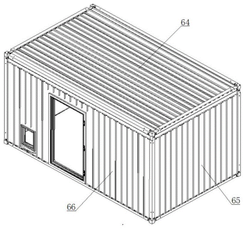
参阅图13、图14、图23、图24,本发明的导风层紧贴隔板层外表面分为五个导风层:顶板导风层64、前壁导风层65、右壁导风层66、左壁导风层67、后壁导风层68。顶板导风层64、前壁导风层65、右壁导风层66、左壁导风层67、后壁导风层68分别对应的位于顶板夹流层框架59、前壁夹流层框架60、右壁夹流层框架61、左壁夹流层框架62、后壁夹流层框架63内部。Referring to Figure 13, Figure 14, Figure 23, Figure 24, the wind guide layer of the present invention is divided into five wind guide layers close to the outer surface of the clapboard layer: the top plate
参阅图13、图14、图15、图16、图23、图25,本发明的顶板导风层64由左侧导风槽69、右侧导风槽70、17个顶板导风带72组成。左侧风槽69与右侧风槽70的截面为U型,宽度为100mm,长度为3830mm,高度为26mm,壁厚2mm。17个顶板导风带72的高度为26mm。左侧风槽69、右侧风槽70分别位于顶板夹流层框架59的右侧与左侧。17个顶板导风带72位于左侧风槽69与右侧风槽70之间,通过16根L型顶板导风板71以间隔120mm隔开。17个顶板导风带72和顶板夹流层框架59的前上横角梁55的17个顶板进风口m与后上横角梁56的17个顶板出风口r对应,形成风道。右侧风槽70与顶板夹流层框架59的前上横角梁55的后壁右侧进风口k、后上横角梁56的后壁右侧导风口q对应,形成后壁右侧导风通道。左侧风槽69与顶板夹流层框架59的前上横角梁55的后壁左侧进风口l、后上横角梁56的后壁左侧导风口p对应,形成后壁左侧导风通道。Referring to Figure 13, Figure 14, Figure 15, Figure 16, Figure 23, Figure 25, the top plate
参阅图13、图21、图23、图25、图26,本发明的前壁导风层65由前壁风槽73和15个前壁导风带75组成。前壁风槽73的截面为U型,宽度为100mm,长度为2238mm,高度为26mm,壁厚为2mm。15个前壁导风带75高度为26mm。前壁风槽73紧贴前壁夹流层框架60的前上横角梁55,15个前壁导风带75位于前壁风槽73下方且前壁风槽73成90度夹角,15个前壁导风带75用14根间隔为150mm的L型前壁导风板74隔开。前壁风槽73与14根L型前壁导风板74焊接在前壁隔板。在前壁风槽73下侧面上每间隔150mm有15个截面为U型、尺寸为46mm×24mm的前壁风槽出风口y。15个前壁导风带75与前壁风槽73下侧面15个前壁风槽出风口y以及前壁夹流层框架60的前下横梁57上的15个前壁出风口w对应,形成15个导风通道。13 , 21 , 23 , 25 and 26 , the front wall
参阅图13、图17、图19、图23、图27、图28、图29,本发明的右壁导风层66由一根右壁风槽82与25个导风带组成。右壁风槽82的截面为U型、宽度为100mm,长度为3827mm,高度为26mm,壁厚为2mm。25个右壁导风带高度为26mm。25个导风带包含13个右壁导风带76、9个舱门框架上部导风带77、3个信号孔口上部导风带78。右壁风槽82与13个右壁导风带76、9个舱门框架上部导风带77、3个信号孔口上部导风带78的高度均为26mm。右壁风槽82紧贴着右壁夹流层框架61的右上长角梁52。13个右壁导风带76、9个舱门框架上部导风带77、3个信号孔口上部导风带78位于右壁风槽82下方且与右壁风槽82成90度夹角。25个导风带之间用24个横截面为L型导风板隔开。24个L型导风板分别为:14个右壁导风板79、8个舱门框架上部导风板80、2个信号孔口上部导风板81。8个舱门框架上部导风板80距离舱门框架150mm处中断。2个信号孔口上部导风板81距离信号孔口150mm处中断。右壁风槽82与右壁夹流层框架61的右前立角梁48的右壁进风口s连通。在右壁风槽82下侧面上每间隔152mm有25个尺寸为46mm×22mm的右壁风槽出风口z。25个右壁风槽出风口z与13个右壁导风带76、9个舱门框架上部导风带77、3个信号孔口上部导风带78连通。13个右壁导风带76与右壁夹流层框架61的右下长梁53中的13个右壁出风口u对应,形成导风通道。9个舱门框架上部导风带77与右壁夹流层框架61的右下长梁53上舱门框架处的2个右壁出风口u对应,形成导风通道。3个信号孔口上部导风带78通过弧形导风板83及其弧形导风板导风口a1与右壁夹流层壁61的右下长梁53上的3个右壁出风口u对应,形成导风通道。13 , 17 , 19 , 23 , 27 , 28 and 29 , the right wall
参阅图13、图14、图17、图20、图24、图30、图31、图32,本发明的左壁导风层68由一根左壁风槽90与25个导风带组成。左壁风槽90的截面为U型,宽度100mm,长度为3827mm,高度为26mm,壁厚2mm。25个导风带高度为26mm。25个导风带包含19个左壁导风带84、6个窗户框架处导风带85。6个窗户框架处导风带85被窗户框架分成窗户框架上部导风带与窗户框架下部导风带。左壁风槽90紧贴着左壁夹流层壁框架62的左上长角梁51。19个左壁导风带84、6个窗户框架处导风带85位于左壁风槽90下方且与左壁风槽90成90度夹角。25个导风带之间用横截面为L型的19个左壁导风板86、5个窗户框架上部导风板87、5个窗户框架下部导风板88隔开。5个窗户框架上部导风板87距离窗户框架150mm处中断,5个窗户框架下部导风板88距离窗户框架300mm处中断。左壁风槽90与左壁夹流层框架62的左前立角梁47的左壁进风口t连通。在左壁风槽90下侧面上每间隔152mm有25个尺寸为46mm×22mm的左壁风槽出风口b1。25个左壁风槽出风口b1与19个左壁导风带84、6个窗户框架处导风带85一一对应并连通。19个左壁导风带84与左壁夹流层62的左下长梁54上的19个左壁出风口v一一对应并连通,形成导风通道。6个窗户框架处导风带85通过窗户框架下部分风板89和左壁夹流层62的左下长梁54上的6个左壁出风口v连通。窗户框架下部分风板89上有4个46mm×16mm腰子型窗户框架处分风口c1。窗户框架下部分风板89与左右两侧的左壁导风板86保持一定的进风间隙,进风间隙以及4个窗户框架处分风口c1使6个窗户框架处导风带85与左壁夹流层62的左下长梁54上的6个左壁出风口v连通,形成导风通道。13 , 14 , 17 , 20 , 24 , 30 , 31 and 32 , the left wall
参阅图13、图14、图22、图24、图33、图34,本发明的后壁导风层68由后壁风槽93和15个后壁导风带91组成。后壁风槽93的截面为U型,宽度为100mm,长度为2238mm,高度为26mm,壁厚2mm。15个后壁导风带91高度为26mm。后壁风槽93紧贴后壁夹流层框架63的后上横角梁56,15个后壁导风带91位于后壁风槽93下方且后壁风槽93成90度夹角,15个后壁导风带91用14根间隔为150mm的L型后壁导风板92隔开。后壁风槽93与14根L型后壁导风板92焊接在前壁隔板。在后壁风槽93上侧面左右两端各有一个尺寸100mm×24mm的后壁左侧导风口d1与后壁右侧导风口e1。在后壁风槽93下侧面上每间隔150mm有15个尺寸为46mm×24mm的后壁风槽出风口f1。15个后壁导风带91与后壁风槽93下侧面的15个后壁风槽出风口f1以及后壁夹流层框架63的后下横梁58上的15个后壁出风口x对应,形成15个导风通道。13 , 14 , 22 , 24 , 33 and 34 , the rear wall
参阅图13、图14、图35、图36、外蒙皮层位于空气夹流层外侧,由五块蒙皮组成,分别为顶板外蒙皮94、前壁外蒙皮95、右壁外蒙皮96、左壁外蒙皮97、后壁外蒙皮98组成,蒙皮材料均为2mm厚的铝板。通过焊接方式将顶板外蒙皮94、前壁外蒙皮95、右壁外蒙皮96、左壁外蒙皮97、后壁外蒙皮98焊接于顶板夹流层框架59、前壁夹流层框架60、右壁夹流层框架61、左壁夹流层框架62、后壁夹流层框架63的外面。舱体包角件固定于的外蒙皮层的8个顶角,并通过M12螺栓穿过外蒙皮层与夹流层骨架、舱体骨架的舱体连接角件连接。8个包角件分别为:前部右上包角件99、前部左上包角件100、2个后部上包角件101、4个下部包角件102。舱门103安装在舱门框架内,信号孔口盖板104安装在信号孔口框架内,窗户105安装在窗户框架内。Referring to Figure 13, Figure 14, Figure 35, Figure 36, the outer skin layer is located on the outside of the air interlayer, and consists of five skins, namely the top plate
图37为本发明的前部左上包角件99,包含前部左上包角件顶板g1、前部左上包角件前板h1、前部左上包角件左侧板i1、吊装环l1。前部左上包角件顶板g1、前部左上包角件前板h1、前部左上包角件左侧板i1厚度均为16mm的钢板,且相互之间成90度夹角焊接。吊装环l1与前部左上包角件顶板g1焊接。在前部左上包角件顶板g1上有3个直径为13mm包角件与舱体连接角件连接孔m1与2个直径为13mm的包角件与夹流层骨架连接孔n1。在前部左上包角件前板h1上有一个尺寸为21mm×100mm的包角件左壁进风口j1、一个尺寸为100mm×21mm的包角件后壁左侧进风口k1、2个M12包角件与进风通道组合连接孔o1以及2个直径为13mm的包角件与夹流层骨架连接孔n1。在前部左上包角件左侧板i1上有2个直径为13mm的包角件与夹流层骨架连接孔n1。Figure 37 is the front left upper
图38为本发明的前部右上包角件100,包含前部右上包角件顶板p1、前部右上包角件前板q1、前部右上包角件右侧板r1、吊装环l1。前部右上包角件顶板p1、前部右上包角件前板q1、前部右上包角件右侧板r1厚度均为16mm的钢板,且相互之间成90度夹角焊接。吊装环l1与前部右上包角件顶板p1焊接。在前部右上包角件顶板p1上有3个直径为13mm包角件与舱体连接角件连接孔m1与2个直径为13mm的包角件与夹流层骨架连接孔n1。在前部右上包角件前板q1上有一个尺寸为21mm×100mm的包角件右壁进风口s1、一个尺寸为100mm×21mm的包角件后壁右侧进风口t1、2个M12包角件与进风通道组合连接孔o1以及2个直径为13mm的包角件与夹流层骨架连接孔n1。在前部右上包角件右侧板r1上有2个直径为13mm的包角件与夹流层骨架连接孔n1。38 is the front right upper
图39为本发明的后部上包角件101,包含后部上包角件顶板u1、2个后部上包角件侧板v1、吊装环l1。后部上包角件顶板u1、2个后部上包角件侧板v1厚度均为16mm的钢板,且相互之间成90度夹角焊接。吊装环l1与后部上包角件顶板u1焊接。在后部上包角件顶板u1上有3个直径为13mm包角件与舱体连接角件连接孔m1与2个直径为13mm的包角件与夹流层骨架连接孔n1。在2个后部上包角件侧板v1上均有2个直径为13mm的包角件与夹流层骨架连接孔n1。FIG. 39 shows the rear upper corner fitting 101 of the present invention, including the rear upper corner fitting top plate u1, two rear upper corner corner fitting side plates v1, and a hoisting ring l1. The top plate u1 of the rear upper corner piece and the two side plates v1 of the rear upper corner piece are all steel plates with a thickness of 16mm, and are welded at a 90-degree angle to each other. The hoisting ring l1 is welded with the top plate u1 of the upper corner piece at the rear. There are three connection holes m1 with a diameter of 13mm between the corner pieces and the cabin body and two holes n1 with a diameter of 13mm on the top plate u1 of the upper corner piece and the interlayer frame. There are two connecting holes n1 of 13mm in diameter between the corner pieces and the interlayer skeleton on the two rear upper corner pieces side plates v1.
图40为本发明的下部包角件102,包含2个下部包角件侧板w1。两个下部包角件侧板w1厚度均为16mm的钢板,且相互之间成90度夹角焊接。在两个下部包角件侧板w1上均有2个直径为13mm的包角件与夹流层骨架连接孔n1与一个直径为13mm包角件与舱体连接角件连接孔m1。FIG. 40 shows the lower
图41为本发明的前壁外蒙皮95,在前壁蒙皮的上部有17个尺寸为46mm×16mm的腰子型前蒙皮顶板进风口x1与15个尺寸为76mm×30mm的腰子型前壁进风口y1。在前壁蒙皮的上边缘左右两侧分别有一个截面为U型、尺寸为100mm×21mm的前蒙皮后壁右侧进风口z1与前蒙皮后壁左侧进风口a2。在前壁蒙皮的左右两边缘分别有一个截面为U型、尺寸为21mm×100mm的前蒙皮右壁进风口b2与前蒙皮左壁进风口c2。17个前蒙皮顶板进风口x1与顶板夹流层框架59的前上横角梁55的17个顶板进风口对应。15个前壁进风口y1与前壁导风层65的前壁风槽73连通。前蒙皮后壁右侧进风口z1与顶板夹流层框架59的前上横角梁55的后壁右侧进风口连通。前蒙皮后壁左侧进风口a2与顶板夹流层框架59的前上横角梁55的后壁左侧进风口连通。前蒙皮右壁进风口b2与右壁夹流层框架61的右前立角梁48的右壁进风口连通。前蒙皮左壁进风口c2与左壁夹流层框架62的左前立角梁47的左壁进风口连通。Figure 41 shows the front wall
图42为本发明的后壁外蒙皮98,在后壁蒙皮的上部有17个尺寸为46mm×16mm的腰子型后蒙皮顶板出风口d2,17个顶板出风口d2与顶板夹流层框架59的后上横角梁56的顶板出风口连通。Fig. 42 is the rear wall
参阅图43,进风通道组合106安装在方舱的前部,通过左右两侧下方进风口分别与风机107连接。Referring to FIG. 43 , the air
图44为本发明的进风道组合内部结构,为左右对称结构,分为右部进风通道108、中部进风通道109、左部进风通道110。中部进风通道109通过风道组合隔板111分为中部上层风道与中部下层风道。中部上层风道对应的进风道组合外壳上有17个尺寸为46mm×16mm腰子型风道组合顶板进风口e2。中部下层风道对应的进风道组合外壳上有15个尺寸为76mm×30mm的腰子型风道组合前壁进风口f2。17个风道组合顶板进风口e2与顶板夹流层框架59的前上横角梁55的17个顶板进风口连通。15个风道组合前壁进风口f2与前壁导风层65的前壁风槽73连通。FIG. 44 shows the internal structure of the air inlet duct assembly of the present invention, which is a left-right symmetrical structure, and is divided into a right
参阅图45、图46、图47、图48、图49,右部进风通道包含:右壁导风管112,后壁导风管113、顶板导风管114、前壁导风管115、右部导风管支撑架116、右部分风板117、右侧进风管118以及铝合金壳体。右壁导风管112、后壁导风管113、顶板导风管114、前壁导风管115采用焊接方式固定在右部导风管支撑架116上。右壁导风管112下部为截面尺寸102mm×75mm右壁导风管进风口g2,上部为截面尺寸21mm×100mm的右壁导风管出风口h2。后壁导风管113下部为截面尺寸102mm×100mm后壁导风管进风口i2,上部为截面尺寸100mm×21mm后壁导风管出风口j2。顶板导风管114下部为截面尺寸102mm×37mm顶板导风管进风口k2,上部为截面尺寸102mm×57mm顶板导风管出风口l2。前壁导风管115下部为截面尺寸102mm×27mm前壁导风管进风口m2,上部为截面尺寸102mm×50mm出风口前壁导风管n2。右侧进风管118位于右部进风通道的下方且与右壁导风管112的右壁导风管进风口g2、后壁导风管113的后壁导风管进风口i2、顶板导风管114的顶板导风管进风口k2、前壁导风管115的前壁导风管进风口m2连通。右部分风板117位于右侧进风管118上部,主要向右壁导风管112导风。右壁导风管112的右壁导风管出风口h2与右壁夹流层框架61的右前立角梁48的右壁进风口对应,形成导风通道。后壁导风管113的后壁导风管出风口j2顶板夹流层框架59的前上横角梁55的后壁右侧进风口对应,形成导风通道。顶板导风管114的顶板导风管出风口l2与中部进风通道109的中部上层风道连通。前壁导风管115的出风口n2与中部进风通道109的中部下层风道连通。45 , 46 , 47 , 48 and 49 , the right air inlet channel includes: right
参阅图47、图48、图49、图50、图51,左部进风通道包含:左壁导风管119,后壁导风管113、顶板导风管114、前壁导风管115、左部导风管支撑架120、左部分风板121、左侧进风管122以及铝合金壳体。左壁导风管119、后壁导风管113、顶板导风管114、前壁导风管115采用焊接方式固定在左部导风管支撑架120上。左侧进风管122位于左部进风通道的下方且与左壁导风管119的左壁导风管进风口o2、后壁导风管114的后壁导风管进风口i2、顶板导风管114的顶板导风管进风口k2、前壁导风管115的前壁导风管进风口m2连通。左部分风板121位于左侧进风管122上部,主要向左壁导风管119导风。左壁导风管119的左壁导风管出风口p2与左壁夹流层框架62的左前立角梁47的左壁进风口对应,形成导风通道。后壁导风管113的后壁导风管出风口j2与顶板夹流层框架59的前上横角梁55的后壁左侧进风口对应,形成导风通道。顶板导风管114的顶板导风管出风口l2与中部进风通道109的中部上层风道连通。前壁导风管115的出风口n2与中部进风通道109的中部下层风道连通。Referring to Figure 47, Figure 48, Figure 49, Figure 50, Figure 51, the left air inlet channel includes: left
参阅图52,在本发明的右部进风通道中,箭头方向为空气流向,空气从右侧进风管118中进入,通过右侧分风板116将空气导向右壁导风管112,后壁导风管113、顶板导风管114、前壁导风管115中。右壁导风管112与后壁导风管113将空气导向进风通道组合后部。顶板导风管114与前壁导风管115将空气分别导向中部进风通道的中部上层风道与中部下层风道。Referring to Figure 52, in the right air inlet channel of the present invention, the direction of the arrow is the air flow direction, the air enters from the right
参阅图53,本发明的左部进风通道中,箭头方向为空气流向,空气从左侧进风管122中进入,通过左部分风板121将空气导向左壁导风管119,后壁导风管113、顶板导风管114、前壁导风管115中。左壁导风管119与后壁导风管113将空气导向进风通道组合后部。顶板导风管114与前壁导风管115将空气分别导向中部进风通道的中部上层风道与中部下层风道。Referring to Figure 53, in the left air inlet channel of the present invention, the direction of the arrow is the air flow direction, the air enters from the left
参阅图54,本发明的中部进风通道中,箭头方向为空气流向。中部上层风道的空气来自左右两侧,通过风道组合顶板进风口e2导向进风道组合后部。中部下层风道空气来自左右两侧,通过风道组合前壁进风口f2导向进风道组合后部。Referring to Figure 54, in the central air inlet channel of the present invention, the direction of the arrow is the air flow direction. The air in the upper air duct in the middle comes from the left and right sides, and is directed to the rear of the air inlet duct assembly through the air inlet e2 of the air duct assembly top plate. The air in the lower air duct in the middle comes from the left and right sides, and is directed to the rear of the air duct assembly through the air inlet f2 on the front wall of the air duct assembly.
图55为本发明的进风道组合的左部进风道110、中部进风道109、右部进风道108后部空气流向,箭头方向为空气流向,进风道组合后部与方舱前壁连接。Figure 55 shows the air flow direction at the rear of the left
图56为本发明顶板导风层空气流向,箭头方向为空气流向,前上横角梁55位于进风道组合后部,空气从前上横角梁55两侧的后壁左侧进风口l、后壁右侧进风口k以及中间17个顶板进风口m分别进入左侧导风槽69、右侧导风槽70、17个顶板导风带72。左侧导风槽69、右侧导风槽70中空气分别从后上横角梁56的后壁左侧导风口p、后壁右侧导风口q进入后壁导风层。17个顶板导风带72中空气从后上横角梁56的17个顶板出风口r排出。Figure 56 is the air flow direction of the top plate air guide layer of the present invention, the direction of the arrow is the air flow direction, the front upper
图57为本发明前壁导风层空气流向,箭头方向为空气流向,前壁风槽73位于进风道组合后部,空气从进风道组合进入前壁风槽73,通过前壁风槽73下侧面15个前壁风槽出风口y进入15个导风带74。15个导风带74中空气通过前下横梁上57的15个前壁出风口w排出。Figure 57 is the air flow direction of the front wall air guide layer of the present invention, the arrow direction is the air flow direction, the front
图58为本发明右壁导风层空气流向,箭头方向为空气流向,右前立角梁48上的右壁进风口位于进风道组合后部,空气从右前立角梁48上的右壁进风进口s入右壁风槽82,通过右壁风槽82下侧面25个右壁风槽出风口z进入13个右壁导风带76、9个舱门框架上部导风带77、3个信号孔口上部导风带78。13个右壁导风带76中的空气通过右下长梁53中的13个右壁出风口u排除。9个舱门框架上部导风带77中的空气从舱门框架两侧导向右下长梁53的两个右壁出风口u排出。3个信号孔口上部导风带77中空气从信号孔口两侧、通过弧形导风板83从右下长梁54上的3个右壁出风口u排出。Figure 58 shows the air flow direction of the air guide layer on the right wall of the present invention, the direction of the arrow is the air flow direction, the right wall air inlet on the right front
图59为本发明左壁导风层空气流向,箭头方向为空气流向,左前立角梁47上的左壁进风口位于进风道组合后部,空气从左前立角梁47上的左壁进风进入左壁风槽90,通过左壁风槽90下侧面25个左壁风槽出风口b1进入19个左壁导风带84、6个窗户框架处导风带85。19个左壁导风带84中空气通过左下长梁54上的19个左壁出风口v排出。6个窗户框架处导风带85中空气从窗户框架两侧通过、经窗户框架下部分风板89分流,从左下长梁54上的6个左壁出风口v排出。Figure 59 is the air flow direction of the left wall air guide layer of the present invention, the direction of the arrow is the air flow direction, the left wall air inlet on the left front
图60为本发明后壁导风层空气流向,箭头方向为空气流向,后壁风槽93位于后上横角梁56下方。空气从后上横角梁56的左侧导风口p与后壁右侧导风口q进入后壁风槽93中,通过后壁风槽93下侧面15个后壁风槽出风口f1进入15个后壁导风带91。15个后壁导风带91中空气通过后下横梁上58的15个后壁出风口x排出。60 shows the air flow direction of the rear wall air guide layer of the present invention, the direction of the arrow is the air flow direction, and the rear
尽管上面已经示出和描述了本发明的实施例,可以理解的是,上述实施例是示例性的,不能理解为对本发明的限制,本领域的普通技术人员在不脱离本发明的原理和宗旨的情况下在本发明的范围内可以对上述实施例进行变化、修改、替换和变型。Although the embodiments of the present invention have been shown and described above, it should be understood that the above embodiments are exemplary and should not be construed as limiting the present invention, and those of ordinary skill in the art will not depart from the principles and spirit of the present invention Variations, modifications, substitutions, and alterations to the above-described embodiments are possible within the scope of the present invention without departing from the scope of the present invention.
Claims (10)
Priority Applications (1)
| Application Number | Priority Date | Filing Date | Title |
|---|---|---|---|
| CN202010541902.1A CN111663807B (en) | 2020-06-15 | 2020-06-15 | Shelter with air clamping layer in bulkhead |
Applications Claiming Priority (1)
| Application Number | Priority Date | Filing Date | Title |
|---|---|---|---|
| CN202010541902.1A CN111663807B (en) | 2020-06-15 | 2020-06-15 | Shelter with air clamping layer in bulkhead |
Publications (2)
| Publication Number | Publication Date |
|---|---|
| CN111663807A true CN111663807A (en) | 2020-09-15 |
| CN111663807B CN111663807B (en) | 2024-06-04 |
Family
ID=72387956
Family Applications (1)
| Application Number | Title | Priority Date | Filing Date |
|---|---|---|---|
| CN202010541902.1A Active CN111663807B (en) | 2020-06-15 | 2020-06-15 | Shelter with air clamping layer in bulkhead |
Country Status (1)
| Country | Link |
|---|---|
| CN (1) | CN111663807B (en) |
Cited By (1)
| Publication number | Priority date | Publication date | Assignee | Title |
|---|---|---|---|---|
| CN112474592A (en) * | 2020-11-09 | 2021-03-12 | 西北工业大学 | Self-cleaning cooling device and method for airborne equipment |
Citations (5)
| Publication number | Priority date | Publication date | Assignee | Title |
|---|---|---|---|---|
| CN202244867U (en) * | 2011-09-16 | 2012-05-30 | 上海航天汽车机电股份有限公司 | Container with ventilation interlayer |
| CN203439508U (en) * | 2013-08-05 | 2014-02-19 | 河北东恒宇功能材料新技术有限公司 | Honeycomb interlayer structured composite material large plate shelter |
| WO2015188229A1 (en) * | 2014-06-10 | 2015-12-17 | Superpod Pty. Ltd. | Improvements in buildings |
| CN110005242A (en) * | 2019-05-10 | 2019-07-12 | 中国工程物理研究院总体工程研究所 | It is a kind of with anti-baked wheaten cake, anticollision, anti-gunshot ability anti-accident shelter |
| CN212613970U (en) * | 2020-06-15 | 2021-02-26 | 西安爱生技术集团公司 | Shelter with air entrainment layer in bulkhead |
-
2020
- 2020-06-15 CN CN202010541902.1A patent/CN111663807B/en active Active
Patent Citations (5)
| Publication number | Priority date | Publication date | Assignee | Title |
|---|---|---|---|---|
| CN202244867U (en) * | 2011-09-16 | 2012-05-30 | 上海航天汽车机电股份有限公司 | Container with ventilation interlayer |
| CN203439508U (en) * | 2013-08-05 | 2014-02-19 | 河北东恒宇功能材料新技术有限公司 | Honeycomb interlayer structured composite material large plate shelter |
| WO2015188229A1 (en) * | 2014-06-10 | 2015-12-17 | Superpod Pty. Ltd. | Improvements in buildings |
| CN110005242A (en) * | 2019-05-10 | 2019-07-12 | 中国工程物理研究院总体工程研究所 | It is a kind of with anti-baked wheaten cake, anticollision, anti-gunshot ability anti-accident shelter |
| CN212613970U (en) * | 2020-06-15 | 2021-02-26 | 西安爱生技术集团公司 | Shelter with air entrainment layer in bulkhead |
Cited By (2)
| Publication number | Priority date | Publication date | Assignee | Title |
|---|---|---|---|---|
| CN112474592A (en) * | 2020-11-09 | 2021-03-12 | 西北工业大学 | Self-cleaning cooling device and method for airborne equipment |
| CN112474592B (en) * | 2020-11-09 | 2021-11-05 | 西北工业大学 | A kind of airborne equipment self-cleaning cooling device and method |
Also Published As
| Publication number | Publication date |
|---|---|
| CN111663807B (en) | 2024-06-04 |
Similar Documents
| Publication | Publication Date | Title |
|---|---|---|
| CN208189676U (en) | Power battery pallet and vehicle | |
| KR20120120137A (en) | Modular data center | |
| CN115295954B (en) | Box structure, battery pack and vehicle | |
| CN115472961A (en) | Energy storage container | |
| US20130047521A1 (en) | Self-Contained Portable Container Habitat For Use In Radiological Environments | |
| CN112061400A (en) | Ultra-light composite aircraft galley architecture | |
| WO2015169116A1 (en) | Container of data centre, and data centre | |
| WO2023179117A1 (en) | Battery box, power battery assembly, and vehicle | |
| US20190375508A1 (en) | Galley and method of assembling a galley | |
| US20220216676A1 (en) | Frame for an explosion-proof housing | |
| CN111663807A (en) | A shelter with an air interlayer in the bulkhead | |
| CN212613970U (en) | Shelter with air entrainment layer in bulkhead | |
| CN115431913A (en) | Battery pack and vehicle | |
| CN108951854B (en) | Micro-modular frame building system | |
| CN217426937U (en) | Energy storage cabinet and modular energy storage unit | |
| JP7389563B2 (en) | Method for manufacturing heat exchanger core with heat exchanger and manifold | |
| EP3945175B1 (en) | Panel | |
| CN203352419U (en) | Integral high-voltage frequency converter | |
| CN111711278A (en) | ISO-compliant energy storage containers | |
| WO2024243988A1 (en) | Formation device | |
| CN105297901B (en) | Easy-to-dismount Split type heat preservation cabin | |
| CN112278298B (en) | A bionic aircraft fuel tank | |
| CN1635826A (en) | An outdoor cabinet | |
| CN115045537A (en) | an energy storage container | |
| CN219261453U (en) | A unitized photovoltaic glass curtain wall system |
Legal Events
| Date | Code | Title | Description |
|---|---|---|---|
| PB01 | Publication | ||
| PB01 | Publication | ||
| SE01 | Entry into force of request for substantive examination | ||
| SE01 | Entry into force of request for substantive examination | ||
| GR01 | Patent grant | ||
| GR01 | Patent grant |