CN111708024B - Spliced sparse planar array millimeter wave imaging device and method - Google Patents
Spliced sparse planar array millimeter wave imaging device and method Download PDFInfo
- Publication number
- CN111708024B CN111708024B CN202010841476.3A CN202010841476A CN111708024B CN 111708024 B CN111708024 B CN 111708024B CN 202010841476 A CN202010841476 A CN 202010841476A CN 111708024 B CN111708024 B CN 111708024B
- Authority
- CN
- China
- Prior art keywords
- array
- dimensional
- sparse
- millimeter wave
- scanning
- Prior art date
- Legal status (The legal status is an assumption and is not a legal conclusion. Google has not performed a legal analysis and makes no representation as to the accuracy of the status listed.)
- Active
Links
Images


Classifications
-
- G—PHYSICS
- G01—MEASURING; TESTING
- G01S—RADIO DIRECTION-FINDING; RADIO NAVIGATION; DETERMINING DISTANCE OR VELOCITY BY USE OF RADIO WAVES; LOCATING OR PRESENCE-DETECTING BY USE OF THE REFLECTION OR RERADIATION OF RADIO WAVES; ANALOGOUS ARRANGEMENTS USING OTHER WAVES
- G01S13/00—Systems using the reflection or reradiation of radio waves, e.g. radar systems; Analogous systems using reflection or reradiation of waves whose nature or wavelength is irrelevant or unspecified
- G01S13/88—Radar or analogous systems specially adapted for specific applications
- G01S13/89—Radar or analogous systems specially adapted for specific applications for mapping or imaging
-
- G—PHYSICS
- G01—MEASURING; TESTING
- G01S—RADIO DIRECTION-FINDING; RADIO NAVIGATION; DETERMINING DISTANCE OR VELOCITY BY USE OF RADIO WAVES; LOCATING OR PRESENCE-DETECTING BY USE OF THE REFLECTION OR RERADIATION OF RADIO WAVES; ANALOGOUS ARRANGEMENTS USING OTHER WAVES
- G01S7/00—Details of systems according to groups G01S13/00, G01S15/00, G01S17/00
- G01S7/02—Details of systems according to groups G01S13/00, G01S15/00, G01S17/00 of systems according to group G01S13/00
- G01S7/41—Details of systems according to groups G01S13/00, G01S15/00, G01S17/00 of systems according to group G01S13/00 using analysis of echo signal for target characterisation; Target signature; Target cross-section
Landscapes
- Engineering & Computer Science (AREA)
- Remote Sensing (AREA)
- Radar, Positioning & Navigation (AREA)
- Physics & Mathematics (AREA)
- Computer Networks & Wireless Communication (AREA)
- General Physics & Mathematics (AREA)
- Electromagnetism (AREA)
- Radar Systems Or Details Thereof (AREA)
- Variable-Direction Aerials And Aerial Arrays (AREA)
Abstract
The millimeter wave signal is transmitted to a one-dimensional sparse array antenna through a receiving and transmitting unit, and meanwhile, the receiving and transmitting unit receives a target echo signal and transmits the target echo signal to a data processing unit; the one-dimensional sparse array antenna is arranged on the two-dimensional moving assembly, and the two-dimensional moving assembly realizes horizontal and vertical movement to complete zigzag scanning movement and obtain echo signals of n sparse planar sub-arrays; and a coordinate recording module is arranged on the two-dimensional moving assembly, and is used for recording the position coordinate information of the one-dimensional sparse array antenna in real time and outputting the position coordinate information to the data processing unit. And the data processing unit is used for performing target imaging according to the echo signals from the transceiving unit and the position coordinate information of the one-dimensional sparse array antenna from the coordinate recording module, and splicing the imaging results of the n sparse planar sub-arrays to obtain a final target imaging result. The invention greatly reduces the hardware cost of the system while ensuring the imaging quality.
Description
Technical Field
The invention belongs to the technical field of millimeter wave radar systems and radar signal processing, and particularly relates to a spliced sparse planar array millimeter wave imaging device and method.
Background
The existing array millimeter wave imaging device utilizes a one-dimensional uniform quasi-single-station linear array to perform plane scanning and cylindrical scanning to image a target. The receiving and transmitting channels of the uniform quasi-single-station linear array are uniformly distributed, and a large number of electronic switches and receiving and transmitting array elements are needed.
In order to reduce the number of array elements, a Sparse co-prime array is proposed in the document [ Sparse Multi-Static Arrays for Near-Field Millimeter-Wave Imaging ], a certain integer proportion exists between the number of transmitting array elements and the number of receiving array elements, and the Imaging quality equivalent to that of a uniformly distributed linear array can be obtained while the number of the array elements is reduced. Compared with the uniform distribution of linear array elements, the array distribution mode has the advantages that the number of the array elements is reduced, but the number of the whole array elements is still large.
Disclosure of Invention
The invention provides a spliced sparse planar array millimeter wave imaging device and method, and aims to solve the problems that the number of switch antennas, the number of receiving and transmitting array elements and the hardware cost are high in the largest problem of the conventional array millimeter wave imaging device.
In order to achieve the technical purpose, the invention adopts the following specific technical scheme:
spliced sparse planar array millimeter wave imaging device includes:
and a millimeter wave signal generating unit which generates a millimeter wave signal.
The receiving and transmitting unit transmits millimeter wave signals to each transmitting array element antenna of the one-dimensional sparse array antenna in sequence, and the transmitting array element antennas radiate the millimeter wave signals to the space for detection; and simultaneously, the receiving and transmitting unit receives echo signals of all receiving array element antennas of the one-dimensional sparse array antenna and transmits the echo signals to the data processing unit.
The one-dimensional sparse array antenna is arranged on the two-dimensional moving assembly, and the two-dimensional moving assembly realizes the movement in the horizontal direction and the vertical direction to complete the zigzag scanning movement and obtain echo signals of n sparse planar sub-arrays; and a coordinate recording module is arranged on the two-dimensional moving assembly, and can record the position coordinate information of the one-dimensional sparse array antenna in real time and output the position coordinate information to the data processing unit.
And the data processing unit is used for imaging the target according to the echo signals from the transceiving unit and the position coordinate information of the one-dimensional sparse array antenna from the coordinate recording module.
In the invention, the scanning motion mode of the one-dimensional sparse array antenna is as follows: setting a scanning starting point of a one-dimensional sparse array antenna, setting n linear array positions at equal intervals in the horizontal direction by taking a horizontal coordinate corresponding to the scanning starting point as a reference, determining the scanning height in the vertical direction, the scanning interval between scanning position points in the vertical direction and the interval between adjacent linear array positions, controlling the one-dimensional sparse array antenna to vertically move along the vertical direction through a two-dimensional moving assembly, starting to scan in the vertical direction for the first time, completing electronic scanning of the one-dimensional sparse array antenna at intervals of the set scanning interval in the vertical direction until the set scanning height in the vertical direction is completed, completing one-time complete scanning in the vertical direction, and obtaining an echo signal of a first sparse planar sub-array; and then, the one-dimensional sparse array antenna is controlled by the two-dimensional moving assembly to move to the next linear array position along the horizontal direction, the next vertical direction scanning is started, and the echo signals of n sparse planar sub-arrays are obtained through n times of vertical direction scanning.
As a preferred scheme of the invention, the millimeter wave signal generating unit comprises a millimeter wave frequency sweeping source and a frequency doubler, wherein the millimeter wave frequency sweeping source generates a 17-20 GHz linearly frequency-modulated millimeter wave signal, and the millimeter wave signal is transmitted to the transceiving unit through the two frequency doublers.
As a preferred scheme of the present invention, the transceiver unit includes a transceiver component and an electronic switch array, the millimeter wave signal generating unit is connected to the electronic switch array through the transceiver component, the electronic switch array is connected to the one-dimensional sparse array antenna, the millimeter wave signal generating unit generates a millimeter wave signal, the millimeter wave signal is transmitted to each transmitting array element antenna of the one-dimensional sparse array antenna through the transceiver component and the electronic switch array, and the electronic switch array receives signals of all receiving array element antennas of the one-dimensional sparse array antenna and transmits the signals back to the transceiver component. Furthermore, the receiving and transmitting component comprises a power divider, a power amplifier, a low noise amplifier and a frequency mixer, wherein the power divider divides the input millimeter wave signal into 2 paths, one path of millimeter wave signal is transmitted to the power amplifier, and the other path of millimeter wave signal is used as a local oscillation signal and is input to a local oscillation port of the frequency mixer; the power amplifier transmits the amplified millimeter wave signals to the electronic switch array; the low-noise amplifier simultaneously receives the returned echo signals, amplifies the echo signals and transmits the amplified echo signals to a radio frequency port of the frequency mixer; after being mixed by the mixer, the intermediate frequency signal is output and transmitted to the data processing unit.
As a preferred scheme of the invention, the one-dimensional sparse array antenna is a one-dimensional four-transmission eight-reception sparse array antenna, and is provided with 4 transmitting array element antennas and 8 receiving array element antennas, wherein the 8 receiving array element antennas are arranged at equal intervals.
As a preferred scheme of the invention, the two-dimensional moving assembly comprises a grating ruler, a horizontal servo motor, a vertical servo motor, a horizontal slider, a vertical slider, a horizontal guide rail and a vertical guide rail, wherein the grating ruler is arranged on each of the horizontal guide rail and the vertical guide rail and is used for acquiring position coordinate information of the one-dimensional sparse array antenna and outputting the position coordinate information to the data processing unit; the one-dimensional sparse array antenna is arranged on a vertical sliding block on a vertical guide rail, the vertical sliding block is in driving connection with a vertical servo motor and can move along the vertical guide rail under the driving of the vertical servo motor, the vertical guide rail is arranged on a horizontal sliding block on a horizontal guide rail, the horizontal sliding block is in driving connection with the horizontal servo motor and can move along the horizontal guide rail under the driving of the horizontal servo motor; the horizontal servo motor and the vertical servo motor are both connected with the data processing unit, and the data processing unit controls the two servo motors to further realize that the one-dimensional sparse array antenna completes scanning movement.
As a preferred scheme of the present invention, the data processing unit includes a data acquisition card and a data processor, the data acquisition card is configured to acquire the intermediate frequency signal from the transceiver component and the position coordinate information from the one-dimensional sparse array antenna of the grating scale, digitize the position coordinate information and transmit the digitized position coordinate information to the data processor; the data processor uses the received digital information to image the target. Furthermore, the data processing unit also comprises a display unit which is connected with the data processor and used for displaying the target imaging result.
On the other hand, the invention provides an imaging method based on the spliced sparse planar array millimeter wave imaging device, which comprises the following steps of:
s1: the one-dimensional sparse array antenna starts scanning movement, the transmitting array element antenna realizes sequential transmission of millimeter wave signals through electronic switch switching at each scanning position point in the scanning movement of the one-dimensional sparse array antenna, all the receiving array element antennas are in a receiving state when each transmitting array element antenna works, and echo signals of n sparse planar sub-arrays are recorded after the whole scanning movement is completed;
s2: at any scanning position point in the scanning motion process of the one-dimensional sparse array antenna, constructing a corresponding radar echo signal model for any transmitting array element antenna of the one-dimensional sparse array antenna as follows:

wherein: 、
、 respectively representing the three-dimensional position coordinates of the scattering points of the target and the complex value scattering intensity corresponding to the three-dimensional position coordinates;
 the horizontal position coordinates of the receiving array element antenna are obtained;
 the array height coordinate of the one-dimensional sparse array antenna is provided;
 is the wave number;
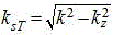 ,
, ,
, and
and are respectively as
 And
And the corresponding spatial wave number;
 the horizontal position coordinates of the transmitting array element antenna are obtained;
s3: relating both ends of the equation of the radar echo signal model And
And fourier transform of (1);

convert the above formula into

Wherein

S4: for additional item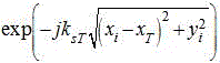 To compensate, will
 The expression of (c) translates into:
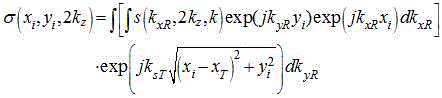
s5: to pair Along the edge
 Performing Fourier transform to obtain a three-dimensional imaging result;
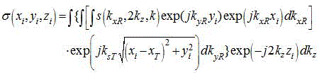
the results of three-dimensional imaging corresponding to the discrete form are expressed as:

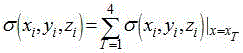
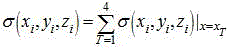
s6: for all scanning position points in the vertical direction scanning process corresponding to any linear array position in the one-dimensional sparse array antenna scanning motion process, obtaining the imaging result of each transmitting array antenna of each scanning position point according to the steps from S2 to S5, and then performing coherent accumulation to obtain the imaging result of the sparse planar sub-array echo signal corresponding to the linear array position, wherein the imaging result is expressed as follows:
s7: and splicing the imaging results of the n sparse planar subarray echo signals to obtain a final target imaging result.
The invention utilizes a millimeter wave frequency sweep source to generate a linear frequency modulated millimeter wave signal, and radiates a millimeter wave detection signal to a space through a receiving and transmitting component, an electronic switch array and a four-transmitting eight-receiving one-dimensional sparse array antenna. Under the combined action of the electronic switch array, the horizontal guide rail, the vertical guide rail, the servo motor and the like, the one-dimensional sparse array antenna is scanned and spliced in the horizontal direction to obtain a long sparse linear array, the imaging field range is expanded, and one-dimensional equal-interval mechanical scanning is utilized in the height direction to further form an equivalent two-dimensional sparse planar array. In the data recording process, the data acquisition card simultaneously acquires intermediate frequency signals of the transceiving component and antenna position information obtained by the grating ruler, so that the antenna positioning precision is improved. At each scanning position point of the four-transmitting eight-receiving sparse array in the scanning motion of the one-dimensional sparse array antenna, the transmitting array element antennas realize sequential transmission through electronic switch switching, and all the receiving array element antennas are in a receiving state when each transmitting array element antenna works. After recording complete sparse planar array echo data, the invention provides a target imaging method under a corresponding system, each sub-sparse planar array formed by vertical scanning of a sparse linear array is subjected to equal field-of-view imaging, and all sparse planar array imaging results are spliced to obtain a final target imaging result. The invention has the following beneficial effects:
the number of the array elements required by the method is less than 10% of that of the traditional scheme, and the hardware cost of the imaging system is greatly reduced.
The spacing of the sparse array is far larger than the quarter wavelength required by the uniform array, so that the difficulty of array integration is greatly reduced.
The invention provides a sparse planar array fast frequency domain imaging method corresponding to the system, the processing flow only comprises simple fast Fourier transform processing and summation processes, imaging can be carried out only aiming at the distance range of an interested target, and the method has high operation efficiency. The whole method flow has no approximate error influencing the imaging quality, and the good imaging effect of the system can be ensured.
Drawings
Fig. 1 is a schematic structural diagram of a spliced sparse planar array millimeter wave imaging device.
Fig. 2 is a schematic diagram of a transmission process of the transceiver module.
Fig. 3 is a position distribution diagram of an array element of a four-shot eight-wire array.
Detailed Description
In order to make the technical scheme and advantages of the present invention more clearly understood, the present invention is further described in detail below with reference to the accompanying drawings and embodiments. It should be understood that the specific embodiments described herein are merely illustrative of the invention and are not intended to limit the invention.
Example 1:
referring to fig. 1 to 3, the present embodiment provides a tiled sparse planar array millimeter wave imaging device, including: the device comprises a millimeter wave frequency sweeping source 1, a frequency doubling link 2, a transceiving component 4, an electronic switch array 3, a one-dimensional four-transmitting eight-receiving sparse array antenna 11, a grating ruler 8, a servo motor 14, a horizontal guide rail 9, a vertical guide rail 10, a data acquisition card 5, a data processor 6 and a display 7.
The millimeter wave frequency sweeping source 1 generates a 17-20 GHz linearly frequency-modulated millimeter wave signal, the broadband signal after passing through a frequency doubling link 2 formed by two frequency doublers is transmitted to the receiving and transmitting assembly 4, the receiving and transmitting assembly 4 comprises a power divider, a power amplifier, a low noise amplifier and a frequency mixer, and the transmission process is as shown in FIG. 2. The power divider divides the millimeter wave signal into 2 paths, one path is transmitted to the power amplifier, and the other path is used as a local oscillation signal and is input to a local oscillation port of the frequency mixer. And the power amplifier transmits the amplified millimeter wave signal to the electronic switch array. And the low noise amplifiers of the eight receiving channels simultaneously receive the returned millimeter wave signals, and transmit the millimeter wave signals to the radio frequency port of the mixer after amplification. And transmitting the eight-channel intermediate frequency signals output by the frequency mixer to a data acquisition card. The electronic switch array sequentially transmits the millimeter wave signals output by the transceiving component to each transmitting antenna of the one-dimensional array antenna, receives signals of all receiving antennas of the one-dimensional array antenna at the same time, and transmits the signals back to the transceiving component.
In this embodiment, the one-dimensional array antenna is composed of 4 transmitting antennas 12 and 8 receiving antennas 13, and the positions of the elements are as shown in fig. 3. The transmitting antenna 12 receives the millimeter wave signal of the electronic switch array 3 and radiates the millimeter wave signal into the space for detection; the receiving antenna 13 receives a target echo signal. In this embodiment, 8 receiving antennas are arranged at equal intervals, the total length of a receiving array formed by the 8 receiving antennas is 14cm, and the interval between adjacent receiving array elements is 2 cm.
And the horizontal guide rail 9 and the vertical guide rail 10 are both provided with a grating ruler 8 for collecting position coordinate information of the one-dimensional sparse array antenna 11 and transmitting the position coordinate information to the data acquisition card 5. The servo motor 14 includes a horizontal direction servo motor and a vertical direction servo motor. The one-dimensional sparse array antenna 11 is mounted on a vertical sliding block (not shown in the figure) on a vertical guide rail 10, the vertical sliding block is in driving connection with a vertical servo motor and can move along the vertical guide rail under the driving of the vertical servo motor, the vertical guide rail 10 is mounted on a horizontal sliding block on a horizontal guide rail 9, the horizontal sliding block is in driving connection with a horizontal servo motor and can move along the horizontal guide rail 9 under the driving of the horizontal servo motor; the horizontal servo motor and the vertical servo motor are both connected with the data processing unit 6, and the data processing unit 6 controls the two servo motors to further realize the zigzag scanning motion of the one-dimensional sparse array antenna 11.
The vertical direction servo motor is controlled by the data processor, the vertical sliding block is driven to drive the one-dimensional sparse array antenna 11 to vertically move along the vertical guide rail 10, the first vertical direction scanning is started, a scanning position point is arranged at a set scanning interval in the vertical direction corresponding to the scanning starting point, the electronic scanning of the one-dimensional sparse array antenna is completed at each scanning position point, and until the scanning of all scanning position points at the set vertical direction scanning height is completed, the complete vertical direction scanning is completed once, and an echo signal of a sparse planar sub-array is obtained. The data processor controls a horizontal servo motor to drive a horizontal sliding block so as to drive the one-dimensional sparse array antenna 11 to horizontally move to the next linear array position along the horizontal guide rail 9, a scanning position point is also arranged at intervals of a set scanning interval in the vertical direction corresponding to the linear array position, the next vertical direction scanning is started, and by analogy, echo signals of five sparse planar sub-arrays are obtained through n times of vertical direction scanning.
A scanning starting point of the one-dimensional sparse array antenna 11 is preset, and n linear array positions are set at equal intervals on the horizontal guide rail 9 by taking a horizontal coordinate corresponding to the scanning starting point as a reference, wherein n = 5. The scanning height in the vertical direction is determined to be 1.8m in the embodiment, and the scanning distance between each scanning position point in the scanning in the vertical direction is 2mm, so that 900 scanning position points are arranged in the vertical direction corresponding to each horizontal line array position. The set interval between adjacent linear array positions is required to meet the requirement that the interval between the leftmost receiving antenna element antenna of the next linear array position and the rightmost receiving antenna element of the last linear array position is the interval between adjacent receiving antenna elements on the one-dimensional sparse array antenna, and the interval is 2cm in this embodiment. The servo motor in the vertical direction drives the one-dimensional sparse array antenna 11 to vertically move along the vertical guide rail 10 under the control of the data processor 6, the first vertical direction scanning is started, the electronic scanning of the one-dimensional sparse array antenna is completed in the vertical direction at intervals of a set scanning interval (2 mm in the embodiment), after the electronic scanning of the one-dimensional array antenna is completed, the servo motor in the vertical direction controls the one-dimensional array antenna to move to the next scanning position point in the vertical direction until the complete vertical direction scanning is completed, and echo signals of sparse planar sub-arrays with the length of 14cm and the height of 1.8m are obtained. After the scanning of a sparse planar subarray is completed, a horizontal servo motor drives a one-dimensional sparse array antenna to move to the next linear array position along a horizontal guide rail under the control of a data processor 6, the next vertical direction scanning is started, and the interval between the leftmost receiving array element antenna of the next linear array position and the rightmost receiving array element antenna of the last linear array position is 2cm, so that the continuity of the imaging result in the azimuth direction is ensured. And finally forming the equivalent two-dimensional sparse planar array antenna of 0.7m multiplied by 1.8m by scanning the positions of the horizontal azimuth linear arrays for 5 times. In the whole mechanical scanning process, the grating ruler records the coordinate position information of the one-dimensional sparse array antenna in real time and transmits signals to the data acquisition card. The data acquisition card acquires eight paths of intermediate frequency signals of the transceiving component and the position information of the one-dimensional array antenna, digitalizes the signals and transmits the signals to the data processor. The data processor performs imaging using the received digital information.
Example 2:
based on the spliced sparse planar array millimeter wave imaging device provided in embodiment 1, this embodiment provides a spliced sparse planar array millimeter wave imaging method:
s1: the one-dimensional sparse array antenna starts scanning movement, the transmitting array element antenna realizes sequential transmission of millimeter wave signals through electronic switch switching at each scanning position point in the one-dimensional sparse array antenna scanning movement, all the receiving array element antennas are in a receiving state when each transmitting array element antenna works, and echo signals of n sparse planar sub-arrays are recorded after the whole scanning movement is completed.
S2: at any scanning position point in the scanning motion process of the one-dimensional sparse array antenna, constructing a corresponding radar echo signal model for any transmitting array element antenna of the one-dimensional sparse array antenna as follows:

in the above formula, the first and second carbon atoms are, 、
、 respectively the three-dimensional position coordinates of the scattering points of the target and the complex-valued scattering intensity corresponding to the three-dimensional position coordinates,
 to receive the horizontal position coordinates of the array element antenna,
 the antenna is a one-dimensional sparse array antenna and the array height coordinate thereof.
 In terms of the wave number, the number of waves,
 in order to be the operating frequency of the system,
 is the speed of light.
 And
And the distances from the transmitting array element antenna and the receiving array element antenna to the target are respectively expressed as follows:


wherein Is the horizontal position coordinate of the transmitting array element antenna. According to the theory of spherical wave expansion, there are:


wherein:


wherein, and
and are respectively as
 And
And the corresponding spatial wavenumber.
Neglecting the influence brought by the amplitude, the final radar echo signal model is expressed as:

s3: relating both ends of the equation of the radar echo signal model And
And fourier transform of (1);

can be further converted into:
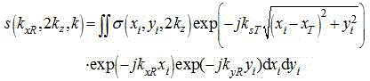
wherein 。
。
S4: for additional item Compensation is performed.
For the traditional self-generating and self-receiving system, the imaging can be realized by direct interpolation and then 3D-FFT, but the imaging can be realized by the direct interpolation and the 3D-FFT Is about
 And
And the influence of this term on the imaging needs to be compensated for.
First fix it And
And at this time is
 Fixed value, redefined
 The imaging area of (2), i.e. the implementation of the additional item
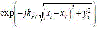 Compensation of (2).
 The expression of (c) can be further translated into:
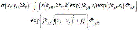
s5: to pair Along the edge
 The result of three-dimensional imaging can be obtained by performing fourier transform, and the imaging result can be expressed as:
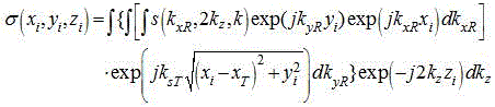
the results of three-dimensional imaging corresponding to the discrete form are expressed as:

s6: for all scanning position points in the vertical direction scanning process corresponding to any linear array position in the one-dimensional sparse array antenna scanning motion process, obtaining the imaging result of each transmitting array antenna of each scanning position point according to the steps from S2 to S5, and then performing coherent accumulation to obtain the imaging result of the sparse planar sub-array echo signal corresponding to the linear array position, wherein the imaging result is expressed as follows:

s7: and splicing the imaging results of the five sparse planar subarray echo signals to obtain a final target imaging result.
According to the embodiment, a short four-transmitting eight-receiving millimeter wave sparse linear array is adopted, a horizontal guide rail and a vertical guide rail are combined, a long sparse linear array is equivalently formed by scanning of a short linear array in the horizontal length direction, and a sparse area array is equivalently formed by adopting an equidistant scanning mode which is the same as that of the traditional scheme in the vertical height direction. The invention only uses 12 array elements, and combines the proposed imaging method, thereby obtaining imaging results with quality equivalent to hundreds of array elements, and greatly reducing the hardware cost of the system.
In summary, although the present invention has been described with reference to the preferred embodiments, it should be understood that various changes and modifications can be made by those skilled in the art without departing from the spirit and scope of the invention.
Claims (9)
1. Spliced sparse planar array millimeter wave imaging device, its characterized in that includes:
a millimeter wave signal generating unit generating a millimeter wave signal;
the receiving and transmitting unit transmits millimeter wave signals to each transmitting array element antenna of the one-dimensional sparse array antenna in sequence, and the transmitting array element antennas radiate the millimeter wave signals to the space for detection; simultaneously, the receiving and transmitting unit receives echo signals of all receiving array element antennas of the one-dimensional sparse array antenna and transmits the echo signals to the data processing unit;
the one-dimensional sparse array antenna is arranged on the two-dimensional moving assembly, and the two-dimensional moving assembly realizes the movement in the horizontal direction and the vertical direction to complete the zigzag scanning movement and obtain echo signals of n sparse planar sub-arrays; the two-dimensional moving assembly is provided with a coordinate recording module which can record the position coordinate information of the one-dimensional sparse array antenna in real time and output the position coordinate information to the data processing unit;
the scanning motion mode of the one-dimensional sparse array antenna is as follows: setting a scanning starting point of a one-dimensional sparse array antenna, setting n linear array positions at equal intervals in the horizontal direction by taking a horizontal coordinate corresponding to the scanning starting point as a reference, determining the scanning height in the vertical direction, the scanning interval between scanning position points in the vertical direction and the interval between adjacent linear array positions, controlling the one-dimensional sparse array antenna to vertically move along the vertical direction through a two-dimensional moving assembly, starting to scan in the vertical direction for the first time, completing electronic scanning of the one-dimensional sparse array antenna at intervals of the set scanning interval in the vertical direction until the set scanning height in the vertical direction is completed, completing one-time complete scanning in the vertical direction, and obtaining an echo signal of a first sparse planar sub-array; then, the one-dimensional sparse array antenna is controlled by the two-dimensional moving assembly to move to the next linear array position along the horizontal direction, next vertical direction scanning is started, and echo signals of n sparse planar sub-arrays are obtained through n times of vertical direction scanning;
the data processing unit is used for imaging a target according to the echo signals from the transceiving unit and the position coordinate information of the one-dimensional sparse array antenna from the coordinate recording module, and the method comprises the following steps:
s1: the one-dimensional sparse array antenna starts scanning movement, the transmitting array element antenna realizes sequential transmission of millimeter wave signals through electronic switch switching at each scanning position point in the scanning movement of the one-dimensional sparse array antenna, all the receiving array element antennas are in a receiving state when each transmitting array element antenna works, and echo signals of n sparse planar sub-arrays are recorded after the whole scanning movement is completed;
s2: at any scanning position point in the scanning motion process of the one-dimensional sparse array antenna, constructing a corresponding radar echo signal model for any transmitting array element antenna of the one-dimensional sparse array antenna as follows:



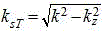


s3: relating both ends of the equation of the radar echo signal model And
And fourier transform of (1);

convert the above formula into

Wherein ;
;
S4: for additional item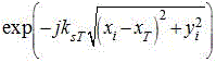 The compensation is carried out and the compensation is carried out,
 the expression of (c) translates into:
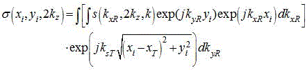
s5: to pair Along the edge
 Performing Fourier transform to obtain a three-dimensional imaging result;
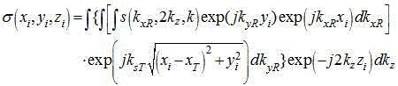
the results of three-dimensional imaging corresponding to the discrete form are expressed as:

s6: for all scanning position points in the vertical direction scanning process corresponding to any linear array position in the one-dimensional sparse array antenna scanning motion process, obtaining the imaging result of each transmitting array antenna of each scanning position point according to the steps from S2 to S5, and then performing coherent accumulation to obtain the imaging result of the sparse planar sub-array echo signal corresponding to the linear array position, wherein the imaging result is expressed as follows:
s7: and splicing the imaging results of the n sparse planar subarray echo signals to obtain a final target imaging result.
2. The spliced sparse planar array millimeter wave imaging device according to claim 1, wherein the millimeter wave signal generating unit comprises a millimeter wave frequency sweeping source and a frequency doubler, the millimeter wave frequency sweeping source generates millimeter wave signals, and the millimeter wave signals are transmitted to the transceiver unit through the two frequency doublers.
3. The spliced sparse planar array millimeter wave imaging device according to claim 2, wherein the millimeter wave frequency sweeping source generates 17-20 GHz linearly frequency-modulated millimeter wave signals.
4. The spliced sparse planar array millimeter wave imaging device according to claim 2, wherein the transceiver unit comprises a transceiver component and an electronic switch array, the millimeter wave signal generating unit is connected with the electronic switch array through the transceiver component, the electronic switch array is connected with the one-dimensional sparse array antenna, the millimeter wave signal generating unit generates millimeter wave signals, the millimeter wave signals are transmitted to each transmitting array element antenna of the one-dimensional sparse array antenna through the transceiver component and the electronic switch array, and the electronic switch array receives signals of all receiving array element antennas of the one-dimensional sparse array antenna and transmits the signals back to the transceiver component.
5. The spliced sparse planar array millimeter wave imaging device according to claim 4, wherein the transceiving component comprises a power divider, a power amplifier, a low noise amplifier and a mixer, the power divider divides the input millimeter wave signal into 2 paths, one path is transmitted to the power amplifier, and the other path is used as a local oscillation signal and is input to a local oscillation port of the mixer; the power amplifier transmits the amplified millimeter wave signals to the electronic switch array; the low-noise amplifier simultaneously receives the returned echo signals, amplifies the echo signals and transmits the amplified echo signals to a radio frequency port of the frequency mixer; after being mixed by the mixer, the intermediate frequency signal is output and transmitted to the data processing unit.
6. The spliced sparse planar array millimeter wave imaging device according to claim 2, wherein the one-dimensional sparse array antenna is a one-dimensional four-transmission eight-reception sparse array antenna, and is provided with 4 transmitting array element antennas and 8 receiving array element antennas, wherein the 8 receiving array element antennas are arranged at equal intervals.
7. The spliced sparse planar array millimeter wave imaging device according to claim 6, wherein the two-dimensional moving assembly comprises a grating ruler, a horizontal direction servo motor, a vertical direction servo motor, a horizontal slider, a vertical slider, a horizontal guide rail and a vertical guide rail, wherein the grating ruler is arranged on each of the horizontal guide rail and the vertical guide rail and is used for acquiring position coordinate information of the one-dimensional sparse array antenna and outputting the position coordinate information to the data processing unit; the one-dimensional sparse array antenna is arranged on a vertical sliding block on a vertical guide rail, the vertical sliding block is in driving connection with a vertical servo motor and can move along the vertical guide rail under the driving of the vertical servo motor, the vertical guide rail is arranged on a horizontal sliding block on a horizontal guide rail, the horizontal sliding block is in driving connection with the horizontal servo motor and can move along the horizontal guide rail under the driving of the horizontal servo motor; the horizontal servo motor and the vertical servo motor are both connected with the data processing unit, and the data processing unit controls the two servo motors to further realize that the one-dimensional sparse array antenna completes scanning movement.
8. The spliced sparse planar array millimeter wave imaging device according to claim 7, wherein the data processing unit comprises a data acquisition card and a data processor, the data acquisition card is used for acquiring intermediate frequency signals from the transceiving component and position coordinate information from the one-dimensional sparse array antenna of the grating ruler, digitizing the position coordinate information and transmitting the digitized position coordinate information to the data processor; the data processor uses the received digital information to image the target.
9. The spliced sparse planar array millimeter wave imaging device according to claim 8, wherein the data processing unit further comprises a display unit, and the display unit is connected with the data processor and used for displaying the target imaging result.
Priority Applications (1)
| Application Number | Priority Date | Filing Date | Title |
|---|---|---|---|
| CN202010841476.3A CN111708024B (en) | 2020-08-20 | 2020-08-20 | Spliced sparse planar array millimeter wave imaging device and method |
Applications Claiming Priority (1)
| Application Number | Priority Date | Filing Date | Title |
|---|---|---|---|
| CN202010841476.3A CN111708024B (en) | 2020-08-20 | 2020-08-20 | Spliced sparse planar array millimeter wave imaging device and method |
Publications (2)
| Publication Number | Publication Date |
|---|---|
| CN111708024A CN111708024A (en) | 2020-09-25 |
| CN111708024B true CN111708024B (en) | 2020-11-10 |
Family
ID=72547366
Family Applications (1)
| Application Number | Title | Priority Date | Filing Date |
|---|---|---|---|
| CN202010841476.3A Active CN111708024B (en) | 2020-08-20 | 2020-08-20 | Spliced sparse planar array millimeter wave imaging device and method |
Country Status (1)
| Country | Link |
|---|---|
| CN (1) | CN111708024B (en) |
Families Citing this family (6)
| Publication number | Priority date | Publication date | Assignee | Title |
|---|---|---|---|---|
| CN113433210B (en) * | 2021-06-24 | 2022-07-29 | 广东工业大学 | Nondestructive testing terahertz linear array radar scanning imaging system and method |
| CN113514832A (en) * | 2021-07-28 | 2021-10-19 | 吉林大学 | Metal flaw detection device and method based on millimeter wave radar SAR imaging |
| CN115296045B (en) * | 2022-09-14 | 2025-08-19 | 重庆两江卫星移动通信有限公司 | Sparse antenna array applied to low-orbit satellite Internet broadband terminal |
| CN116520321B (en) * | 2022-12-05 | 2024-07-19 | 重庆邮电大学 | MIMO array arrangement with half-wavelength uniform scanning and synthetic aperture imaging method thereof |
| CN116908804B (en) * | 2023-08-31 | 2026-03-17 | 北京航空航天大学 | Angle estimation method for motion-assisted sparse uniform linear array millimeter-wave radar |
| CN117970247B (en) * | 2023-12-08 | 2024-08-16 | 青岛柯锐思德电子科技有限公司 | Method for measuring wireless earphone position based on integrated UWB multi-antenna earphone charging bin |
Citations (6)
| Publication number | Priority date | Publication date | Assignee | Title |
|---|---|---|---|---|
| CN105005036A (en) * | 2015-07-16 | 2015-10-28 | 中国电子科技集团公司第四十一研究所 | Transmission loss compensation method used for short-range MIMO imaging |
| CN205450265U (en) * | 2015-12-25 | 2016-08-10 | 深圳市太赫兹科技创新研究院 | Human security inspection system based on holographic three -dimensional imaging of millimeter wave |
| CN105932427A (en) * | 2016-05-04 | 2016-09-07 | 西安电子工程研究所 | Millimeter-wave imaging radar one-dimensional array antenna and sequential control method |
| CN109991600A (en) * | 2019-04-19 | 2019-07-09 | 山东省科学院自动化研究所 | Single-station planar array millimeter wave imaging device and method |
| CN111226131A (en) * | 2017-08-21 | 2020-06-02 | 阿斯泰克斯有限责任公司 | Imaging radar system with a receive array for determining the angle of an object in two dimensions by an extended arrangement of one-dimensional receive antennas |
| CN111505629A (en) * | 2020-05-08 | 2020-08-07 | 中国科学院国家空间科学中心 | Terahertz security inspection imaging system and method |
Family Cites Families (3)
| Publication number | Priority date | Publication date | Assignee | Title |
|---|---|---|---|---|
| US10845463B2 (en) * | 2015-07-17 | 2020-11-24 | Origin Wireless, Inc. | Method, apparatus, and system for wireless object scanning |
| US10000000B2 (en) * | 2015-03-10 | 2018-06-19 | Raytheon Company | Coherent LADAR using intra-pixel quadrature detection |
| US10209356B2 (en) * | 2015-11-24 | 2019-02-19 | Mitsubishi Electric Research Laboratories, Inc. | Method and system for autofocus radar imaging |
-
2020
- 2020-08-20 CN CN202010841476.3A patent/CN111708024B/en active Active
Patent Citations (6)
| Publication number | Priority date | Publication date | Assignee | Title |
|---|---|---|---|---|
| CN105005036A (en) * | 2015-07-16 | 2015-10-28 | 中国电子科技集团公司第四十一研究所 | Transmission loss compensation method used for short-range MIMO imaging |
| CN205450265U (en) * | 2015-12-25 | 2016-08-10 | 深圳市太赫兹科技创新研究院 | Human security inspection system based on holographic three -dimensional imaging of millimeter wave |
| CN105932427A (en) * | 2016-05-04 | 2016-09-07 | 西安电子工程研究所 | Millimeter-wave imaging radar one-dimensional array antenna and sequential control method |
| CN111226131A (en) * | 2017-08-21 | 2020-06-02 | 阿斯泰克斯有限责任公司 | Imaging radar system with a receive array for determining the angle of an object in two dimensions by an extended arrangement of one-dimensional receive antennas |
| CN109991600A (en) * | 2019-04-19 | 2019-07-09 | 山东省科学院自动化研究所 | Single-station planar array millimeter wave imaging device and method |
| CN111505629A (en) * | 2020-05-08 | 2020-08-07 | 中国科学院国家空间科学中心 | Terahertz security inspection imaging system and method |
Non-Patent Citations (3)
| Title |
|---|
| A fast imaging algorithm for sparse array imaging based on PCA and modified SLIM methods;孟祥新 等;《红外与毫米波学报》;20200630;第39卷(第3期);第300-305页 * |
| 毫米波成像快速扫描分析;戚福伟;《中国优秀硕士学位论文全文数据库 信息科技辑》;20130615;第I138-1299页 * |
| 毫米波成像系统天线设计;纪泽栋;《中国优秀硕士学位论文全文数据库 信息科技辑》;20130115;第I136-26页 * |
Also Published As
| Publication number | Publication date |
|---|---|
| CN111708024A (en) | 2020-09-25 |
Similar Documents
| Publication | Publication Date | Title |
|---|---|---|
| CN111708024A (en) | Spliced sparse planar array millimeter wave imaging device and method | |
| Yanik et al. | Development and demonstration of MIMO-SAR mmWave imaging testbeds | |
| US7714765B2 (en) | Synthetic aperture perimeter array radar | |
| CN106872975B (en) | A millimeter wave active near-field imaging device | |
| US11313963B2 (en) | Millimeter wave holographic three-dimensional imaging detection system and method | |
| CN109358372B (en) | Millimeter wave transceiver antenna array, millimeter wave scanning imaging system and imaging method thereof | |
| CN105699493B (en) | High ferro nondestructive detection system and method | |
| CN112558064B (en) | Three-dimensional imaging system based on reconfigurable electromagnetic surface array | |
| CN105606630A (en) | System and method for non-destructive testing of missile casing | |
| Baccouche et al. | A sparse array based sub-terahertz imaging system for volume inspection | |
| CN109884627B (en) | Short-range millimeter wave rapid three-dimensional imaging method of any linear array configuration | |
| JP5080795B2 (en) | Imaging device | |
| US20230350055A1 (en) | Radar and method for target detection using radar | |
| Shoykhetbrod et al. | Concept for a fast tracking 60 GHz 3D-radar using frequency scanning antennas | |
| CN113126084A (en) | Multiple-sending multiple-receiving antenna array arrangement for active millimeter wave security inspection imaging, human body security inspection equipment and method | |
| CN105629229B (en) | Plane nondestructive detecting system and method | |
| CN110109096A (en) | The dual station mm-wave imaging device and method of loss balancing | |
| Yang et al. | Development and implementation of ultra-wideband see-through-wall imaging system based on sampling oscilloscope | |
| CN115421134A (en) | Method and device for resolving ambiguity of radar speed and millimeter wave radar | |
| JP3378200B2 (en) | RCS measurement device and RCS measurement method | |
| CN109991600A (en) | Single-station planar array millimeter wave imaging device and method | |
| CN113433210A (en) | Nondestructive testing terahertz linear array radar scanning imaging system and method | |
| CN114660595B (en) | Frequency diversity circular array radar imaging method for emitting vortex electromagnetic waves | |
| CN210129038U (en) | Single-station plane array millimeter wave imaging device | |
| JPH03179282A (en) | Bistatic radar apparatus |
Legal Events
| Date | Code | Title | Description |
|---|---|---|---|
| PB01 | Publication | ||
| PB01 | Publication | ||
| SE01 | Entry into force of request for substantive examination | ||
| SE01 | Entry into force of request for substantive examination | ||
| GR01 | Patent grant | ||
| GR01 | Patent grant |