CN111708321A - Device and method for detecting dynamic error of CNC machine tool axis direction - Google Patents

Device and method for detecting dynamic error of CNC machine tool axis direction Download PDF

Info

Publication number
CN111708321A
CN111708321A CN202010514029.7A CN202010514029A CN111708321A CN 111708321 A CN111708321 A CN 111708321A CN 202010514029 A CN202010514029 A CN 202010514029A CN 111708321 A CN111708321 A CN 111708321A
Authority
CN
China
Prior art keywords
displacement
machine tool
data
numerical control
coordinate system
Prior art date
Legal status (The legal status is an assumption and is not a legal conclusion. Google has not performed a legal analysis and makes no representation as to the accuracy of the status listed.)
Granted
Application number
CN202010514029.7A
Other languages
Chinese (zh)
Other versions
CN111708321B (en
Inventor
毕庆贞
许坤
钟磊
钱德厚
Current Assignee (The listed assignees may be inaccurate. Google has not performed a legal analysis and makes no representation or warranty as to the accuracy of the list.)
Shanghai Jiao Tong University
Original Assignee
SHANGHAI TOP NUMERICAL CONTROL TECHNOLOGY CO LTD
Shanghai Jiao Tong University
Priority date (The priority date is an assumption and is not a legal conclusion. Google has not performed a legal analysis and makes no representation as to the accuracy of the date listed.)
Filing date
Publication date
Application filed by SHANGHAI TOP NUMERICAL CONTROL TECHNOLOGY CO LTD, Shanghai Jiao Tong University filed Critical SHANGHAI TOP NUMERICAL CONTROL TECHNOLOGY CO LTD
Priority to CN202010514029.7A priority Critical patent/CN111708321B/en
Publication of CN111708321A publication Critical patent/CN111708321A/en
Application granted granted Critical
Publication of CN111708321B publication Critical patent/CN111708321B/en
Active legal-status Critical Current
Anticipated expiration legal-status Critical

Links

Images

Classifications

    • GPHYSICS
    • G05CONTROLLING; REGULATING
    • G05BCONTROL OR REGULATING SYSTEMS IN GENERAL; FUNCTIONAL ELEMENTS OF SUCH SYSTEMS; MONITORING OR TESTING ARRANGEMENTS FOR SUCH SYSTEMS OR ELEMENTS
    • G05B19/00Program-control systems
    • G05B19/02Program-control systems electric
    • G05B19/18Numerical control [NC], i.e. automatically operating machines, in particular machine tools, e.g. in a manufacturing environment, so as to execute positioning, movement or co-ordinated operations by means of program data in numerical form
    • G05B19/401Numerical control [NC], i.e. automatically operating machines, in particular machine tools, e.g. in a manufacturing environment, so as to execute positioning, movement or co-ordinated operations by means of program data in numerical form characterised by control arrangements for measuring, e.g. calibration and initialisation, measuring workpiece for machining purposes
    • GPHYSICS
    • G05CONTROLLING; REGULATING
    • G05BCONTROL OR REGULATING SYSTEMS IN GENERAL; FUNCTIONAL ELEMENTS OF SUCH SYSTEMS; MONITORING OR TESTING ARRANGEMENTS FOR SUCH SYSTEMS OR ELEMENTS
    • G05B19/00Program-control systems
    • G05B19/02Program-control systems electric
    • G05B19/18Numerical control [NC], i.e. automatically operating machines, in particular machine tools, e.g. in a manufacturing environment, so as to execute positioning, movement or co-ordinated operations by means of program data in numerical form
    • G05B19/404Numerical control [NC], i.e. automatically operating machines, in particular machine tools, e.g. in a manufacturing environment, so as to execute positioning, movement or co-ordinated operations by means of program data in numerical form characterised by control arrangements for compensation, e.g. for backlash, overshoot, tool offset, tool wear, temperature, machine construction errors, load, inertia

Landscapes

  • Engineering & Computer Science (AREA)
  • Human Computer Interaction (AREA)
  • Manufacturing & Machinery (AREA)
  • Physics & Mathematics (AREA)
  • General Physics & Mathematics (AREA)
  • Automation & Control Theory (AREA)
  • Numerical Control (AREA)

Abstract

本发明提供了一种数控机床刀轴方向动态误差检测装置及方法,数控机床刀轴方向动态误差检测装置包括数控系统、机床主轴、测量杆、位移传感器、位移测量装置底座及连接装置;数控系统连接机床主轴,控制机床主轴运动;测量杆的长度能够调节;测量杆与机床主轴通过机床刀具夹具装夹连接;位移传感器与位移测量装置底座连接,位移传感器能够对不同长度的测量杆的位移数据进行采集;位移测量装置底座通过连接装置与机床连接。本发明通过采用长度能够调节的测量杆,实现了对刀轴方向误差的检测,解决了采用传统位移测量装置的方法仅能测量刀尖点位置误差,无法反映刀轴方向变化的问题。

Figure 202010514029

The invention provides a dynamic error detection device and method for a tool axis direction of a numerically controlled machine tool. The dynamic error detection device for a tool axis of a numerically controlled machine tool includes a numerical control system, a machine tool spindle, a measuring rod, a displacement sensor, a displacement measuring device base and a connecting device; the numerical control system Connect the machine tool spindle to control the movement of the machine tool spindle; the length of the measuring rod can be adjusted; the measuring rod and the machine tool spindle are clamped and connected through the tool fixture of the machine tool; the displacement sensor is connected with the base of the displacement measuring device, and the displacement sensor can measure the displacement data of the measuring rod of different lengths The acquisition is carried out; the base of the displacement measuring device is connected with the machine tool through the connecting device. The invention realizes the detection of the tool axis direction error by using the measuring rod whose length can be adjusted, and solves the problem that the traditional displacement measuring device can only measure the tool tip position error and cannot reflect the change of the tool axis direction.

Figure 202010514029

Description

Device and method for detecting dynamic error of cutter shaft direction of numerical control machine tool
Technical Field
The invention relates to a measuring device on a machine tool, in particular to a device and a method for detecting the dynamic error of a cutter shaft direction of a numerical control machine tool.
Background
Many researchers today have designed various test traces and methods to test the dynamic performance of five-axis machine tools using various test instruments (e.g., a ball bar machine (DBB) R-test, laser tracking interferometer). Masaomi et al devised a method of evaluating the accuracy of a rotating shaft using circular trajectory measurement of DBB. Bell Lei et al propose to use R-test to carry on the tiny S orbit test in the journey, and then the method to analyze the dynamic error of the lathe. In international standard ISO 10791-6: 2014, four kinematic test methods are defined for evaluating the dynamic accuracy of five-axis machine tools having three typical configurations. The kinematic testing method can effectively detect the dynamic error of the central point of the machine tool cutter, but the kinematic testing method cannot be used for detecting the dynamic error of the cutter shaft direction.
The chinese patent document with application number 201410811379.4 discloses a synchronous detection mechanism for tool attitude and tool nose point position errors of a five-axis machine tool, and the technical scheme needs a special detection mechanism, and has complex mechanism structure and high design and manufacturing cost.
Disclosure of Invention
Aiming at the defects in the prior art, the invention aims to provide a device and a method for detecting the dynamic error of the cutter shaft direction of a numerical control machine tool.
The invention provides a device for detecting the dynamic error of a numerical control machine tool shaft direction, which comprises a numerical control system, a machine tool main shaft, a measuring rod, a displacement sensor, a displacement measuring device base and a connecting device, wherein the measuring rod is arranged on the machine tool main shaft;
the numerical control system is connected with the machine tool spindle and controls the machine tool spindle to move;
the length of the measuring rod can be adjusted;
the measuring rod is connected with the machine tool spindle in a clamping manner through a machine tool clamp;
the displacement sensor is connected with the displacement measuring device base and can acquire displacement data of the measuring rods with different lengths;
the displacement measuring device base is connected with the machine tool through the connecting device.
Preferably, the measuring rod comprises an elongate rod.
Preferably, the top of displacement measurement device base is equipped with the mounting hole, displacement sensor pass through the mounting hole with the top of displacement measurement device base is dismantled and is connected.
Preferably, the bottom of the displacement measuring device base is detachably connected with the machine tool workbench.
According to the method for detecting the dynamic error of the numerical control machine tool in the cutter shaft direction, which is provided by the invention, the device for detecting the dynamic error of the numerical control machine tool in the cutter shaft direction comprises the following steps:
step A: installing a numerical control machine tool cutter shaft direction dynamic error detection device;
and B: preparing a numerical control system;
and C: respectively acquiring displacement data of measuring rods with different lengths under the same set motion track;
step D: respectively acquiring error data of measuring rods with different lengths under the same set motion track;
step E: and acquiring the dynamic error of the cutter shaft direction of the numerical control machine tool.
Preferably, the step a comprises the steps of:
step A1: connecting the numerical control system with a machine tool spindle;
step A2: clamping the measuring rod on the machine tool spindle through a machine tool cutter clamp;
step A3: connecting a displacement sensor with the top of a base of a displacement measuring device;
step A4: and connecting the bottom of the base of the displacement measuring device with a machine tool workbench through a connecting device.
Preferably, the step B includes the steps of:
step B1: writing a numerical control system program which can set the motion track of the machine tool spindle;
step B2: and importing the numerical control system program into the numerical control system.
Preferably, the step C includes the steps of:
step C1: setting the length of the measuring rod to L1Controlling the movement of the main shaft of the machine tool through the numerical control system, wherein the set movement track is S1In the motion process, the displacement sensor collects the actual displacement data M of the measuring rod in real time1
Step C2: setting the length of the measuring rod to L2Controlling the movement of the main shaft of the machine tool by the same numerical control system, wherein the set movement track is S2In the motion process, the displacement sensor collects the actual displacement data M of the measuring rod in real time2Wherein the length L of the measuring rod1Is not equal to L2The set motion profile S1And S2Are identical.
Preferably, the step D includes the steps of:
step D1: the data processing system measures the actual displacement data M in the coordinate system me1And theoretical displacement data G1All through a space coordinate transformation matrix
Figure BDA0002529477520000031
Converting to obtain a space three-dimensional coordinate array m under a machine tool coordinate system Ma1And g1The calculation formula is as follows:
Figure BDA0002529477520000032
Figure BDA0002529477520000033
wherein,
Figure BDA0002529477520000034
a spatial coordinate transformation matrix for transforming from the measurement coordinate system me to the machine coordinate system Ma;
subscript 1 indicates the length of the measuring rod as L1Data of time;
M1actual displacement data under the measurement coordinate system me;
G1the theoretical displacement data under the measurement coordinate system me is obtained;
m1for the actual displacement data M under the machine coordinate system Ma1A spatial three-dimensional coordinate array of (a);
g1for the theoretical displacement data G under the machine coordinate system Ma1A spatial three-dimensional coordinate array of (a);
is a dot product operation of the matrix;
the data processing system carries out three-dimensional coordinate array m on the actual displacement space1And said theoretical displacement space three-dimensional coordinate array g1Calculating to obtain the length L1The displacement error data e of the measuring rod in three spatial X/Y/Z directions1The calculation formula is as follows:
Figure BDA0002529477520000035
wherein,
e1is the length L under the machine coordinate system Ma1Displacement error data of the measuring rod;
e1xas the displacement error data e1A component in the X direction under the machine coordinate system Ma;
e1yas the displacement error data e1A component in the Y direction under the machine coordinate system Ma;
e1zas the displacement error data e1A component in the Z direction under the machine coordinate system Ma;
[ …, …, … ] is a matrix symbol;
t is the transposition of the matrix;
step D2: the data processing system measures the actual displacement data M in the coordinate system me2And theoretical displacement data G2All through airInter-coordinate transformation matrix
Figure BDA0002529477520000036
Converting to obtain a space three-dimensional coordinate array m under a machine tool coordinate system Ma2And g2The calculation formula is as follows:
Figure BDA0002529477520000037
Figure BDA0002529477520000038
wherein,
Figure BDA0002529477520000039
a spatial coordinate transformation matrix for transforming from the measurement coordinate system me to the machine coordinate system Ma;
the subscript 2 indicates the length of the measuring rod as L2Data of time;
M2actual displacement data under the measurement coordinate system me;
G2the theoretical displacement data under the measurement coordinate system me is obtained;
m2for the actual displacement data M under the machine coordinate system Ma2A spatial three-dimensional coordinate array of (a);
g2for the theoretical displacement data G under the machine coordinate system Ma2A spatial three-dimensional coordinate array of (a);
a dot product operation representing a matrix;
the data processing system carries out three-dimensional coordinate array m on the actual displacement space2And said theoretical displacement space three-dimensional coordinate array g2Calculating to obtain the length L2The displacement error data e of the measuring rod in three spatial X/Y/Z directions2The calculation formula is as follows:
Figure BDA0002529477520000041
wherein,
e2is the length L under the machine coordinate system Ma2Displacement error data of the measuring rod;
e2xas the displacement error data e2A component in the X direction under the machine coordinate system Ma;
e2yas the displacement error data e2A component in the Y direction under the machine coordinate system Ma;
e2zas the displacement error data e2A component in the Z direction under the machine coordinate system Ma;
[ …, …, … ] is a matrix symbol;
t is the transpose of the matrix.
Preferably, the step E includes:
the data processing system is based on the displacement error data e1And e2Calculating to obtain the dynamic error E of the numerical control machine tool in the cutter shaft direction through the following formulad
Figure BDA0002529477520000042
Wherein,
Edthe dynamic error of the numerical control machine tool cutter shaft direction is obtained;
max (..) is a max function, and the maximum value of the expression in brackets is obtained;
e1idenotes e at the ith measurement point1
e2iDenotes e at the ith measurement point2
N represents the total number of measurement points i in the measurement;
|e2i-e1ii is the ith measurement point, the displacement error data e1And the displacement error data e2A difference module representing the length of the displacement error difference under the machine coordinate system Ma;
L2-L1 is the measuring rod length L2And L1Length of (2)The absolute value of the difference value represents the variation of the length of the measuring rod in two measurements;
Figure BDA0002529477520000051
is a mathematical division operator.
Compared with the prior art, the invention has the following beneficial effects:
1. by adopting the measuring rod with adjustable length, the detection of the error of the cutter shaft direction is realized, and the problem that the position error of the cutter point can only be measured by adopting the traditional displacement measuring device and the change of the cutter shaft direction cannot be reflected is solved;
2. by adopting the measuring rod with adjustable length, the measuring device for measuring the position error of the tool nose point can detect the direction error of the cutter shaft of the machine tool, and the problem of high design cost caused by the need of designing a device specially aiming at measuring the direction error of the cutter shaft is solved;
3. through adopting the measuring stick that length can be adjusted, realized adjusting measuring stick length and detected arbor direction error, the flow is simple, detects with low costsly.
Drawings
Other features, objects and advantages of the invention will become more apparent upon reading of the detailed description of non-limiting embodiments with reference to the following drawings:
FIG. 1 is a schematic structural diagram of a device for detecting dynamic errors in the cutter axis direction of a numerical control machine tool;
fig. 2 is a flow chart of a method for detecting dynamic errors of a numerical control machine tool in the cutter shaft direction.
Detailed Description
The present invention will be described in detail with reference to specific examples. The following examples will assist those skilled in the art in further understanding the invention, but are not intended to limit the invention in any way. It should be noted that it would be obvious to those skilled in the art that various changes and modifications can be made without departing from the spirit of the invention. All falling within the scope of the present invention.
The following describes an embodiment of a device for detecting a dynamic error of a numerical control machine tool in a cutter shaft direction according to the present invention.
Fig. 1 shows a device for detecting a dynamic error of a numerical control machine tool in a cutter shaft direction according to the present invention.
The invention provides a device for detecting the dynamic error of a numerical control machine tool in the cutter shaft direction, which comprises a numerical control system, a machine tool main shaft 1, a measuring rod 2, a displacement sensor 3, a displacement measuring device base 4 and a connecting device 5.
The numerical control system is connected with the machine tool spindle 1 and controls the machine tool spindle 1 to move.
The length of the measuring rod 2 is adjustable, preferably the measuring rod 2 comprises an extension rod, so that the length of the measuring rod 2 extending out of the machine spindle 1 is adjustable. Preferably, the measuring shaft 2 comprises a section of a ball bar, one end of which is used for coaxially connecting the machine spindle 1 and the other end is used as a measuring end. Preferably, a standard ball is fixed at the measuring end as a preferred object of displacement measurement. The measuring rod 2 is connected with the machine tool spindle 1 in a clamping mode through a machine tool clamp.
The displacement sensor 3 is connected with the displacement measuring device base 4, preferably, the top of the displacement measuring device base 4 is provided with a mounting hole, and the displacement sensor 3 is detachably connected with the top of the displacement measuring device base 4 through the mounting hole. The displacement sensor 3 on the displacement measuring device base 4 can measure the displacement information of the measuring ends of the measuring rods 2 with different lengths in the movement process, and preferably, the displacement data of the standard ball is measured. The displacement sensor 3 and the displacement measuring device base 4 form a displacement measuring device, and the displacement measuring device can simultaneously measure the spatial X/Y/Z three-coordinate data of a measuring object (preferably a standard ball).
The displacement measuring device base 4 is connected with the machine tool through a connecting device 5, preferably, the connecting device 5 is a fastener, and the bottom of the displacement measuring device base 4 is detachably and fixedly connected with the workbench of the machine tool.
Preferably, the system also comprises a data processing system, and the data processing system is connected with the displacement sensor 3 and the numerical control system.
The following describes an embodiment of a method for detecting a dynamic error in a cutter axis direction of a numerical control machine tool provided by the present invention.
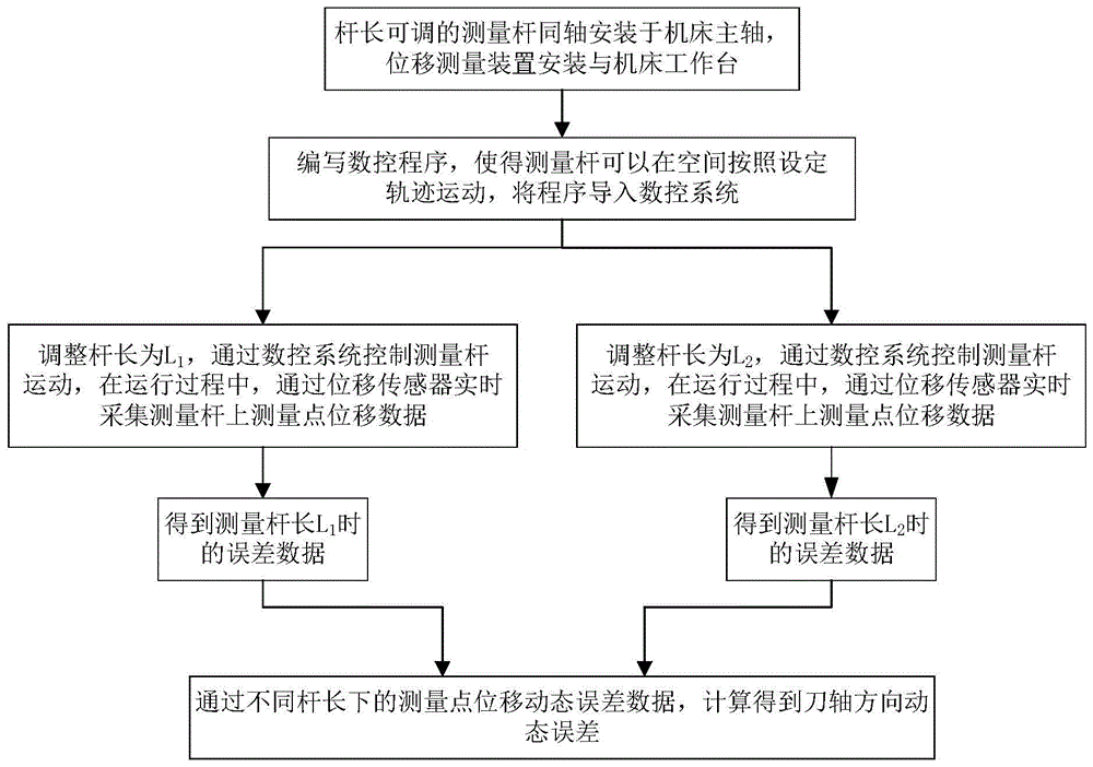
Fig. 2 is a flow chart of the method for detecting the dynamic error of the numerical control machine tool in the cutter shaft direction provided by the invention.
The basic principle of the numerical control machine tool cutter shaft direction dynamic error detection method is as follows:
at a length L of the measuring rod 21During measurement, the displacement sensor 3 is used for measuring and obtaining the displacement data of the measuring end of the measuring rod 2, because the measuring rod 2 is a rigid body, the displacement data of the measuring end of the measuring rod 2 can be equivalent to the error data of the tool nose point, and then the length of the measuring rod 2 is changed to L2And the length of the changed rod is set in the tool length compensation function of the numerical control machine tool, and the numerical control machine tool can automatically and linearly compensate the length change of the measuring rod 2 through the motion amount change of each axis of the machine tool, so that the measuring rod 2 can move according to the same track. Because the compensation of the amount of exercise is that the digit control machine tool carries on according to the ideal arbor direction down, the error of arbor direction can reflect on the displacement error of knife tip point under different measuring stick 2 lengths, therefore, through measuring the knife tip point error under different measuring stick 2 lengths, can calculate and obtain the digit control machine tool arbor direction dynamic error.
According to the method for detecting the dynamic error of the numerical control machine tool in the cutter shaft direction, which is provided by the invention, the device for detecting the dynamic error of the numerical control machine tool in the cutter shaft direction comprises the following steps:
step A: installing a numerical control machine tool cutter shaft direction dynamic error detection device;
and B: preparing a numerical control system;
and C: respectively acquiring displacement data of measuring rods 2 with different lengths under the same set motion track;
step D: respectively acquiring error data of measuring rods 2 with different lengths under the same set motion track;
step E: and acquiring the dynamic error of the cutter shaft direction of the numerical control machine tool.
The step A comprises the following steps:
step A1: connecting a numerical control system and a machine tool spindle 1;
step A2: clamping a measuring rod 2 on a machine tool spindle 1 through a machine tool fixture;
step A3: connecting the displacement sensor 3 with the top of a displacement measuring device base 4;
step A4: the bottom of a displacement measuring device base 4 is connected with a machine tool workbench through a connecting device 5, and position correction is carried out after installation is finished.
The step B comprises the following steps:
step B1: compiling a numerical control system program, wherein the numerical control system program can set the motion track of the machine tool spindle 1, so that the measuring rod 2 can move in space according to the set track;
step B2: and importing the numerical control system program into the numerical control system.
The step C comprises the following steps:
step C1: the length of the measuring rod 2 is set to L1The numerical control program is operated through the numerical control system to control the machine tool spindle 1 to move according to a set track, and the set motion track is S1The measuring rod 2 moves along with the bed main shaft 1, and in the moving process, the displacement sensor 3 collects the actual displacement data M at the specific measuring point A on the measuring rod 2 in real time1
Step C2: the extension length of the measuring rod 2 on the machine tool spindle 1 is changed by adding an extension rod, and the length of the measuring rod 2 is set to be L2After the setting is finished, the position calibration is carried out again; running a numerical control program through the same numerical control system to control the machine tool spindle 1 to move according to a set track S2The measuring rod 2 moves along with the bed main shaft 1, and in the moving process, the displacement sensor 3 collects the actual displacement data M at the specific measuring point B on the measuring rod 2 in real time2Wherein the length L of the rod 2 is measured1Is not equal to L2Setting a motion trajectory S1And S2Are identical. The specific measuring point A and the specific measuring point B are selected to ensure that the distances from the point A and the point B to the rotation center of the rotation shaft of the machine tool spindle 1 are different, preferably, the point A and the point B are selected to be the same point under measuring rods with different lengths, namely, a standard ball at the measuring end of the measuring rod 2 is measured, so that the influence of the manufacturing error of the measuring points on the measuring result is reduced.
Preferably, step C may be repeated i timesEach time step C is repeated, another specific measurement point is selected again to measure the length L of the rod 21、L2And setting a motion trajectory S1、S2Other measurement conditions are kept unchanged to obtain i groups of actual displacement data M1And M2
The step D comprises the following steps:
step D1: the data processing system measures the actual displacement data M under a coordinate system (space rectangular coordinate system) me1And theoretical displacement data G1All through a space coordinate transformation matrix
Figure BDA0002529477520000071
Converting to obtain a space three-dimensional coordinate array m under a machine tool coordinate system Ma1And g1The calculation formula is as follows:
Figure BDA0002529477520000072
Figure BDA0002529477520000073
wherein,
Figure BDA0002529477520000074
the space coordinate transformation matrix is converted from the measurement coordinate system me to the machine tool coordinate system Ma and is determined by the machine tool structure;
the subscript 1 indicates that the length of the measuring stick 2 is L1Data of time;
M1actual displacement data under a measurement coordinate system me;
G1measuring theoretical displacement data under a coordinate system me;
m1is the actual displacement data M under the machine tool coordinate system Ma1A spatial three-dimensional coordinate array of (a);
g1is theoretical displacement data G under a machine tool coordinate system Ma1A spatial three-dimensional coordinate array of (a);
is a dot product operation of a vector or matrix;
the data processing system is used for carrying out three-dimensional coordinate array m on actual displacement space1And a theoretical displacement space three-dimensional coordinate array g1Calculating to obtain the length L1The displacement error data e of the measuring rod 2 in three spatial X/Y/Z directions1The calculation formula is as follows:
Figure BDA0002529477520000081
wherein,
e1is the length L under the machine coordinate system Ma1Displacement error data of the measuring rod 2;
e1xas displacement error data e1The component in the X direction under the machine coordinate system Ma;
e1yas displacement error data e1The component in the Y direction under the machine coordinate system Ma;
e1zas displacement error data e1Component in the Z direction under the machine coordinate system Ma;
[ …, …, … ] is a matrix symbol;
t is the transpose of a matrix or vector;
step D2: the data processing system measures the actual displacement data M under the coordinate system me2And theoretical displacement data G2All through a space coordinate transformation matrix
Figure BDA0002529477520000082
Converting to obtain a space three-dimensional coordinate array m under a machine tool coordinate system Ma2And g2The calculation formula is as follows:
Figure BDA0002529477520000083
Figure BDA0002529477520000084
wherein,
Figure BDA0002529477520000085
the space coordinate transformation matrix is converted from the measurement coordinate system me to the machine tool coordinate system Ma and is determined by the machine tool structure;
the subscript 2 indicates that the length of the measuring rod 2 is L2Data of time;
M2actual displacement data under a measurement coordinate system me;
G2measuring theoretical displacement data under a coordinate system me;
m2is the actual displacement data M under the machine tool coordinate system Ma2A spatial three-dimensional coordinate array of (a);
g2is theoretical displacement data G under a machine tool coordinate system Ma2A spatial three-dimensional coordinate array of (a);
a dot product operation representing a vector or matrix;
the data processing system is used for carrying out three-dimensional coordinate array m on actual displacement space2And a theoretical displacement space three-dimensional coordinate array g2Calculating to obtain the length L2The displacement error data e of the measuring rod 2 in three spatial X/Y/Z directions2The calculation formula is as follows:
Figure BDA0002529477520000091
wherein,
e2is the length L under the machine coordinate system Ma2Displacement error data of the measuring rod 2;
e2xas displacement error data e2The component in the X direction under the machine coordinate system Ma;
e2yas displacement error data e2The component in the Y direction under the machine coordinate system Ma;
e2zas displacement error data e2Component in the Z direction under the machine coordinate system Ma;
[ …, …, … ] is a matrix symbol;
t is the transpose of a matrix or vector.
The step E comprises the following steps:
the data processing system is based on the displacement error data e1And e2Calculating to obtain the dynamic error E of the numerical control machine tool cutter shaft direction by the following formulad
Figure BDA0002529477520000092
Wherein,
Edthe dynamic error of the cutter shaft direction of the numerical control machine tool is obtained;
max (..) is a max function, and the maximum value of the expression in brackets is obtained;
e1idenotes e at the ith measurement point1
e2iDenotes e at the ith measurement point2
N represents the total number of measurement points i in the measurement;
|e2i-e1ii is displacement error data e at the ith measuring point1And displacement error data e2A differential mode, which represents the length of the displacement error difference under the machine coordinate system Ma;
L2-L1 is the length L of the measuring rod2And L1The absolute value of the length difference of (a) represents the amount of change in the length of the measuring rod 2 in the two measurements;
Figure BDA0002529477520000093
is a mathematical division operator.
In the description of the present application, it is to be understood that the terms "upper", "lower", "front", "rear", "left", "right", "vertical", "horizontal", "top", "bottom", "inner", "outer", and the like indicate orientations or positional relationships based on those shown in the drawings, and are only for convenience in describing the present application and simplifying the description, but do not indicate or imply that the referred device or element must have a specific orientation, be constructed in a specific orientation, and be operated, and thus, should not be construed as limiting the present application.
The foregoing description of specific embodiments of the present invention has been presented. It is to be understood that the present invention is not limited to the specific embodiments described above, and that various changes or modifications may be made by one skilled in the art within the scope of the appended claims without departing from the spirit of the invention. The embodiments and features of the embodiments of the present application may be combined with each other arbitrarily without conflict.

Claims (10)

1. A device for detecting the dynamic error of the cutter shaft direction of a numerical control machine tool is characterized by comprising a numerical control system, a machine tool main shaft (1), a measuring rod (2), a displacement sensor (3), a displacement measuring device base (4) and a connecting device (5);
the numerical control system is connected with the machine tool spindle (1) and controls the machine tool spindle (1) to move;
the length of the measuring rod (2) can be adjusted;
the measuring rod (2) is connected with the machine tool spindle (1) in a clamping manner through a machine tool clamp;
the displacement sensor (3) is connected with the displacement measuring device base (4), and the displacement sensor (3) can collect displacement data of the measuring rods (2) with different lengths;
the displacement measuring device base (4) is connected with the machine tool through the connecting device (5).
2. The device for detecting the dynamic error of the cutter shaft direction of the numerical control machine tool according to claim 1, wherein the measuring rod (2) comprises an extension rod.
3. The device for detecting the dynamic error of the cutter shaft direction of the numerical control machine tool according to claim 1, wherein a mounting hole is formed in the top of the displacement measuring device base (4), and the displacement sensor (3) is detachably connected with the top of the displacement measuring device base (4) through the mounting hole.
4. The device for detecting the dynamic error of the cutter shaft direction of the numerical control machine tool according to claim 1, wherein the bottom of the displacement measuring device base (4) is detachably connected with the machine tool workbench.
5. A method for detecting dynamic errors of cutter shaft directions of a numerical control machine tool is characterized in that the device for detecting the dynamic errors of the cutter shaft directions of the numerical control machine tool, which is disclosed by claims 1-4, is adopted, and the method comprises the following steps:
step A: installing a numerical control machine tool cutter shaft direction dynamic error detection device;
and B: preparing a numerical control system;
and C: respectively acquiring displacement data of measuring rods (2) with different lengths under the same set motion track;
step D: error data of measuring rods (2) with different lengths under the same set motion track are respectively obtained;
step E: and acquiring the dynamic error of the cutter shaft direction of the numerical control machine tool.
6. The method for detecting the dynamic error of the cutter shaft direction of the numerical control machine tool according to claim 5, wherein the step A comprises the following steps:
step A1: connecting the numerical control system with a machine tool spindle (1);
step A2: clamping the measuring rod (2) on the machine tool spindle (1) through a machine tool clamp;
step A3: connecting a displacement sensor (3) with the top of a displacement measuring device base (4);
step A4: and connecting the bottom of the displacement measuring device base (4) with a machine tool workbench through a connecting device (5).
7. The method for detecting the dynamic error of the cutter shaft direction of the numerical control machine tool according to claim 5, wherein the step B comprises the following steps:
step B1: writing a numerical control system program which can set the motion track of the machine tool spindle (1);
step B2: and importing the numerical control system program into the numerical control system.
8. The method for detecting the dynamic error of the cutter shaft direction of the numerical control machine tool according to claim 5, wherein the step C comprises the following steps:
step C1: setting the length of the measuring rod (2) to L1The numerical control system controls the machine tool spindle (1) to move, and the set motion track is S1In the motion process, the displacement sensor (3) collects the actual displacement data M of the measuring rod (2) in real time1
Step C2: setting the length of the measuring rod (2) to L2Controlling the machine tool spindle (1) to move through the same numerical control system, wherein the set motion track is S2In the motion process, the displacement sensor (3) collects the actual displacement data M of the measuring rod (2) in real time2Wherein the length L of the measuring rod (2)1Is not equal to L2The set motion profile S1And S2Are identical.
9. The method for detecting the dynamic error of the cutter shaft direction of the numerical control machine tool according to the claim 5 or 8, wherein the step D comprises the following steps:
step D1: the data processing system measures the actual displacement data M in the coordinate system me1And theoretical displacement data G1All through a space coordinate transformation matrix
Figure FDA0002529477510000021
Converting to obtain a space three-dimensional coordinate array m under a machine tool coordinate system Ma1And g1The calculation formula is as follows:
Figure FDA0002529477510000022
Figure FDA0002529477510000023
wherein,
Figure FDA0002529477510000024
a spatial coordinate transformation matrix for transforming from the measurement coordinate system me to the machine coordinate system Ma;
the subscript 1 indicates that the length of the measuring rod (2) is L1Data of time;
M1actual displacement data under the measurement coordinate system me;
G1the theoretical displacement data under the measurement coordinate system me is obtained;
m1for the actual displacement data M under the machine coordinate system Ma1A spatial three-dimensional coordinate array of (a);
g1for the theoretical displacement data G under the machine coordinate system Ma1A spatial three-dimensional coordinate array of (a);
is a dot product operation of the matrix;
the data processing system carries out three-dimensional coordinate array m on the actual displacement space1And said theoretical displacement space three-dimensional coordinate array g1Calculating to obtain the length L1Displacement error data e of the measuring rod (2) in three spatial X/Y/Z directions1The calculation formula is as follows:
Figure FDA0002529477510000031
wherein,
e1is the length L under the machine coordinate system Ma1Displacement error data of the measuring rod (2);
e1xas the displacement error data e1A component in the X direction under the machine coordinate system Ma;
e1yas the displacement error data e1A component in the Y direction under the machine coordinate system Ma;
e1zas the displacement error data e1A component in the Z direction under the machine coordinate system Ma;
[ …, …, … ] is a matrix symbol;
the superscript T is the transpose of the matrix;
step D2: the data processing system measures the actual displacement data M in the coordinate system me2And theoretical displacement data G2All through a space coordinate transformation matrix
Figure FDA0002529477510000032
Converting to obtain a space three-dimensional coordinate array m under a machine tool coordinate system Ma2And g2The calculation formula is as follows:
Figure FDA0002529477510000033
Figure FDA0002529477510000034
wherein,
Figure FDA0002529477510000035
a spatial coordinate transformation matrix for transforming from the measurement coordinate system me to the machine coordinate system Ma;
the subscript 2 indicates that the length of the measuring rod (2) is L2Data of time;
M2actual displacement data under the measurement coordinate system me;
G2the theoretical displacement data under the measurement coordinate system me is obtained;
m2for the actual displacement data M under the machine coordinate system Ma2A spatial three-dimensional coordinate array of (a);
g2for the theoretical displacement data G under the machine coordinate system Ma2A spatial three-dimensional coordinate array of (a);
a dot product operation representing a matrix;
the data processing system carries out three-dimensional coordinate array m on the actual displacement space2And said theoretical displacement space three-dimensional coordinate array g2Performing calculation to obtain theLength L2Displacement error data e of the measuring rod (2) in three spatial X/Y/Z directions2The calculation formula is as follows:
Figure FDA0002529477510000036
wherein,
e2is the length L under the machine coordinate system Ma2Displacement error data of the measuring rod (2);
e2xas the displacement error data e2A component in the X direction under the machine coordinate system Ma;
e2yas the displacement error data e2A component in the Y direction under the machine coordinate system Ma;
e2zas the displacement error data e2A component in the Z direction under the machine coordinate system Ma;
[ …, …, … ] is a matrix symbol;
the superscript T is the transpose of the matrix.
10. The method for detecting the dynamic error of the cutter shaft direction of the numerical control machine tool according to claim 5, wherein the step E comprises the following steps:
the data processing system is based on the displacement error data e1And e2Calculating to obtain the dynamic error E of the numerical control machine tool in the cutter shaft direction through the following formulad
Figure FDA0002529477510000041
Wherein,
Edthe dynamic error of the numerical control machine tool cutter shaft direction is obtained;
max (..) is a max function, and the maximum value of the expression in brackets is obtained;
e1ie at the measurement point representing the ith measurement1
e2iE at the measurement point representing the ith measurement2
N represents the number of measurements;
|e2i-e1i| is the measurement point of the ith measurement, the displacement error data e1And the displacement error data e2A difference module representing the length of the displacement error difference under the machine coordinate system Ma;
L2-L1 is the measuring rod length L2And L1Represents the amount of change in the length of the measuring rod (2).
CN202010514029.7A 2020-06-08 2020-06-08 Device and method for detecting dynamic error of cutter shaft direction of numerical control machine tool Active CN111708321B (en)

Priority Applications (1)

Application Number Priority Date Filing Date Title
CN202010514029.7A CN111708321B (en) 2020-06-08 2020-06-08 Device and method for detecting dynamic error of cutter shaft direction of numerical control machine tool

Applications Claiming Priority (1)

Application Number Priority Date Filing Date Title
CN202010514029.7A CN111708321B (en) 2020-06-08 2020-06-08 Device and method for detecting dynamic error of cutter shaft direction of numerical control machine tool

Publications (2)

Publication Number Publication Date
CN111708321A true CN111708321A (en) 2020-09-25
CN111708321B CN111708321B (en) 2021-06-04

Family

ID=72539420

Family Applications (1)

Application Number Title Priority Date Filing Date
CN202010514029.7A Active CN111708321B (en) 2020-06-08 2020-06-08 Device and method for detecting dynamic error of cutter shaft direction of numerical control machine tool

Country Status (1)

Country Link
CN (1) CN111708321B (en)

Cited By (3)

* Cited by examiner, † Cited by third party
Publication number Priority date Publication date Assignee Title
CN113778018A (en) * 2021-08-25 2021-12-10 西安交通大学 R-test-based five-axis machine tool shaft vector error measurement method
WO2022067596A1 (en) * 2020-09-30 2022-04-07 成都飞机工业(集团)有限责任公司 Standard ball array-based geometric error detection method for machine tool
CN116047996A (en) * 2023-01-13 2023-05-02 上海拓璞数控科技股份有限公司 Method and system for automatically calibrating the spatial accuracy of machine tools using the measuring field

Citations (13)

* Cited by examiner, † Cited by third party
Publication number Priority date Publication date Assignee Title
WO2009007824A1 (en) * 2007-07-11 2009-01-15 Tekno Alfa S.R.L. Two-axes-compensation and anticollision device mounted between an industrial robot and its tool
CN103809513A (en) * 2012-11-09 2014-05-21 沈阳高精数控技术有限公司 Error verification method of CA oscillating structure five-axis machine tool
CN104308657A (en) * 2014-10-14 2015-01-28 浙江大学 Machine tool rotating shaft geometry error six-circle identifying method based on measuring of ball bar instrument
US20150068054A1 (en) * 2002-02-14 2015-03-12 Faro Technologies, Inc. Portable coordinate measurement machine having a handle that includes electronics
US20150094844A1 (en) * 2013-10-02 2015-04-02 Korea Institute Of Machinery & Materials Built-in type vision based inspection tool for autonomous setting of initial origin
CN104625880A (en) * 2014-12-23 2015-05-20 电子科技大学 Five-axis machine tool cutter posture and cutter point position error synchronous detection mechanism
CN105127840A (en) * 2015-09-08 2015-12-09 清华大学 Spindle head attitude angle measuring device and measuring method of five-axis linkage machine tool
CN105479271A (en) * 2016-01-29 2016-04-13 电子科技大学 Sphere center centring and positioning device for five-axis machine tool error synchronous detection mechanism
WO2016113894A1 (en) * 2015-01-16 2016-07-21 富士機械製造株式会社 Machine tool
CN106112693A (en) * 2016-07-01 2016-11-16 上海拓璞数控科技有限公司 A kind of five-axle number control machine tool translation shaft and rotary shaft synchronous error detection method
CN107450473A (en) * 2017-08-03 2017-12-08 南京航空航天大学 A kind of calculating of CFXYZA types five-axle number control machine tool rotary shaft geometric error, compensation and its verification method
US20180036854A1 (en) * 2015-03-02 2018-02-08 Makino Milling Machine Co., Ltd. Method for evaluating tool installation, and machine tool
CN111215967A (en) * 2019-11-27 2020-06-02 上海交通大学 Device and method for detecting dynamic precision of numerical control machine tool

Patent Citations (13)

* Cited by examiner, † Cited by third party
Publication number Priority date Publication date Assignee Title
US20150068054A1 (en) * 2002-02-14 2015-03-12 Faro Technologies, Inc. Portable coordinate measurement machine having a handle that includes electronics
WO2009007824A1 (en) * 2007-07-11 2009-01-15 Tekno Alfa S.R.L. Two-axes-compensation and anticollision device mounted between an industrial robot and its tool
CN103809513A (en) * 2012-11-09 2014-05-21 沈阳高精数控技术有限公司 Error verification method of CA oscillating structure five-axis machine tool
US20150094844A1 (en) * 2013-10-02 2015-04-02 Korea Institute Of Machinery & Materials Built-in type vision based inspection tool for autonomous setting of initial origin
CN104308657A (en) * 2014-10-14 2015-01-28 浙江大学 Machine tool rotating shaft geometry error six-circle identifying method based on measuring of ball bar instrument
CN104625880A (en) * 2014-12-23 2015-05-20 电子科技大学 Five-axis machine tool cutter posture and cutter point position error synchronous detection mechanism
WO2016113894A1 (en) * 2015-01-16 2016-07-21 富士機械製造株式会社 Machine tool
US20180036854A1 (en) * 2015-03-02 2018-02-08 Makino Milling Machine Co., Ltd. Method for evaluating tool installation, and machine tool
CN105127840A (en) * 2015-09-08 2015-12-09 清华大学 Spindle head attitude angle measuring device and measuring method of five-axis linkage machine tool
CN105479271A (en) * 2016-01-29 2016-04-13 电子科技大学 Sphere center centring and positioning device for five-axis machine tool error synchronous detection mechanism
CN106112693A (en) * 2016-07-01 2016-11-16 上海拓璞数控科技有限公司 A kind of five-axle number control machine tool translation shaft and rotary shaft synchronous error detection method
CN107450473A (en) * 2017-08-03 2017-12-08 南京航空航天大学 A kind of calculating of CFXYZA types five-axle number control machine tool rotary shaft geometric error, compensation and its verification method
CN111215967A (en) * 2019-11-27 2020-06-02 上海交通大学 Device and method for detecting dynamic precision of numerical control machine tool

Non-Patent Citations (2)

* Cited by examiner, † Cited by third party
Title
TAN JIUBIN, ZHANG JIE: "A small probe with a gradient index lens for confocal measurement", 《SENSORS AND ACTUATORS》 *
刘健: "R-test五轴数控机床旋转轴误差测量系统设计", 《中国优秀硕士学位论文全文数据库 工程科技I辑》 *

Cited By (4)

* Cited by examiner, † Cited by third party
Publication number Priority date Publication date Assignee Title
WO2022067596A1 (en) * 2020-09-30 2022-04-07 成都飞机工业(集团)有限责任公司 Standard ball array-based geometric error detection method for machine tool
CN113778018A (en) * 2021-08-25 2021-12-10 西安交通大学 R-test-based five-axis machine tool shaft vector error measurement method
CN113778018B (en) * 2021-08-25 2023-04-07 西安交通大学 A Method of Measuring Vector Error of Tool Axis of Five-Axis Machine Tool Based on R-test
CN116047996A (en) * 2023-01-13 2023-05-02 上海拓璞数控科技股份有限公司 Method and system for automatically calibrating the spatial accuracy of machine tools using the measuring field

Also Published As

Publication number Publication date
CN111708321B (en) 2021-06-04

Similar Documents

Publication Publication Date Title
CN100504687C (en) System and method for measuring, compensating and testing numerically controlled machine tool heads and/or tables
CN111215967B (en) Device and method for detecting dynamic accuracy of numerically controlled machine tool
EP1579168B1 (en) Workpiece inspection method and apparatus
KR910005508B1 (en) Computerized Kinetic Transducer Link System and Method for Measuring and Analyzing NC Machine Tool Precision Using the System
EP1446636B2 (en) Dynamic artefact comparison
CN103827637B (en) Calibration and operation of rotary devices, in particular for rotating probes and/or probes of coordinate measuring machines
Du et al. Development of a multi-step measuring method for motion accuracy of NC machine tools based on cross grid encoder
CN101947746B (en) Laser interference-based ball arm measuring device and method
CN111708321A (en) Device and method for detecting dynamic error of CNC machine tool axis direction
CN105556253A (en) Reducing errors of a rotary device, in particular for the determination of coordinates of a workpiece or the machining of a workpiece
CN101432592A (en) error calibration
CN113467371B (en) R-test-based five-axis machine tool RTCP parameter calibration method
CN112405112B (en) Five-axis machine tool linkage error detection device and measurement method
CN110220454A (en) A kind of pose scaling method of three coordinate locating mechanisms
CN102200429A (en) Precision detection method for numerical control machine based on laser-tracking combined measurement
CN119618065B (en) Planar sphere joint constraint spectral confocal probe space pose position calibration method
CN109163658A (en) A kind of scaling method for the optical reference part can provide position and angle reference
US20080028626A1 (en) Use Of Surface Measurement Probes
CN106796095B (en) Method of operating coordinate measuring apparatus, coordinate measuring apparatus and computer program
CN113282055B (en) Small-stroke and high-precision two-axis linkage error measurement system and control method
CN116533065B (en) In-machine measurement system temperature measuring device and measurement thermal error compensation method based on the device
CN201014951Y (en) Portable three-coordinate measuring machine precision automatic calibration instrument
Xu et al. Synchronization motion accuracy measurement method for coordinated five-axis machine tools
CN121143193B (en) A method, apparatus, and storage medium for measuring errors in a five-axis machine tool.
CN112809037A (en) Method for drilling on curved surface structure

Legal Events

Date Code Title Description
PB01 Publication
PB01 Publication
SE01 Entry into force of request for substantive examination
GR01 Patent grant
GR01 Patent grant
TR01 Transfer of patent right

Effective date of registration: 20210702

Address after: 200240 No. 800, Dongchuan Road, Shanghai, Minhang District

Patentee after: SHANGHAI JIAO TONG University

Address before: 200240 No. 800, Dongchuan Road, Shanghai, Minhang District

Patentee before: SHANGHAI JIAO TONG University

Patentee before: SHANGHAI TOP NUMERICAL CONTROL TECHNOLOGY Co.,Ltd.

TR01 Transfer of patent right