CN111745540B - Supporting member for polishing optical fiber ferrule - Google Patents
Supporting member for polishing optical fiber ferrule Download PDFInfo
- Publication number
- CN111745540B CN111745540B CN201911210876.8A CN201911210876A CN111745540B CN 111745540 B CN111745540 B CN 111745540B CN 201911210876 A CN201911210876 A CN 201911210876A CN 111745540 B CN111745540 B CN 111745540B
- Authority
- CN
- China
- Prior art keywords
- optical fiber
- fiber ferrule
- polishing
- wall
- support wall
- Prior art date
- Legal status (The legal status is an assumption and is not a legal conclusion. Google has not performed a legal analysis and makes no representation as to the accuracy of the status listed.)
- Active
Links
- 239000013307 optical fiber Substances 0.000 title claims abstract description 203
- 238000005498 polishing Methods 0.000 title claims abstract description 101
- 238000003780 insertion Methods 0.000 claims abstract description 47
- 230000037431 insertion Effects 0.000 claims abstract description 47
- 238000000034 method Methods 0.000 description 7
- 230000000694 effects Effects 0.000 description 3
- 239000000835 fiber Substances 0.000 description 3
- 238000010586 diagram Methods 0.000 description 2
- 238000010276 construction Methods 0.000 description 1
- 230000007423 decrease Effects 0.000 description 1
- 230000000994 depressogenic effect Effects 0.000 description 1
Images




Classifications
-
- B—PERFORMING OPERATIONS; TRANSPORTING
- B24—GRINDING; POLISHING
- B24B—MACHINES, DEVICES, OR PROCESSES FOR GRINDING OR POLISHING; DRESSING OR CONDITIONING OF ABRADING SURFACES; FEEDING OF GRINDING, POLISHING, OR LAPPING AGENTS
- B24B19/00—Single-purpose machines or devices for particular grinding operations not covered by any other main group
- B24B19/22—Single-purpose machines or devices for particular grinding operations not covered by any other main group characterised by a special design with respect to properties of the material of non-metallic articles to be ground
- B24B19/226—Single-purpose machines or devices for particular grinding operations not covered by any other main group characterised by a special design with respect to properties of the material of non-metallic articles to be ground of the ends of optical fibres
-
- B—PERFORMING OPERATIONS; TRANSPORTING
- B24—GRINDING; POLISHING
- B24B—MACHINES, DEVICES, OR PROCESSES FOR GRINDING OR POLISHING; DRESSING OR CONDITIONING OF ABRADING SURFACES; FEEDING OF GRINDING, POLISHING, OR LAPPING AGENTS
- B24B41/00—Component parts such as frames, beds, carriages, headstocks
- B24B41/06—Work supports, e.g. adjustable steadies
-
- B—PERFORMING OPERATIONS; TRANSPORTING
- B24—GRINDING; POLISHING
- B24B—MACHINES, DEVICES, OR PROCESSES FOR GRINDING OR POLISHING; DRESSING OR CONDITIONING OF ABRADING SURFACES; FEEDING OF GRINDING, POLISHING, OR LAPPING AGENTS
- B24B19/00—Single-purpose machines or devices for particular grinding operations not covered by any other main group
-
- B—PERFORMING OPERATIONS; TRANSPORTING
- B24—GRINDING; POLISHING
- B24B—MACHINES, DEVICES, OR PROCESSES FOR GRINDING OR POLISHING; DRESSING OR CONDITIONING OF ABRADING SURFACES; FEEDING OF GRINDING, POLISHING, OR LAPPING AGENTS
- B24B29/00—Machines or devices for polishing surfaces on work by means of tools made of soft or flexible material with or without the application of solid or liquid polishing agents
- B24B29/02—Machines or devices for polishing surfaces on work by means of tools made of soft or flexible material with or without the application of solid or liquid polishing agents designed for particular workpieces
- B24B29/06—Machines or devices for polishing surfaces on work by means of tools made of soft or flexible material with or without the application of solid or liquid polishing agents designed for particular workpieces for elongated workpieces having uniform cross-section in one main direction
- B24B29/08—Machines or devices for polishing surfaces on work by means of tools made of soft or flexible material with or without the application of solid or liquid polishing agents designed for particular workpieces for elongated workpieces having uniform cross-section in one main direction the cross-section being circular, e.g. tubes, wires, needles
-
- G—PHYSICS
- G02—OPTICS
- G02B—OPTICAL ELEMENTS, SYSTEMS OR APPARATUS
- G02B6/00—Light guides; Structural details of arrangements comprising light guides and other optical elements, e.g. couplings
- G02B6/24—Coupling light guides
- G02B6/36—Mechanical coupling means
- G02B6/38—Mechanical coupling means having fibre to fibre mating means
- G02B6/3807—Dismountable connectors, i.e. comprising plugs
- G02B6/3833—Details of mounting fibres in ferrules; Assembly methods; Manufacture
- G02B6/3863—Details of mounting fibres in ferrules; Assembly methods; Manufacture fabricated by using polishing techniques
Landscapes
- Engineering & Computer Science (AREA)
- Mechanical Engineering (AREA)
- Physics & Mathematics (AREA)
- General Physics & Mathematics (AREA)
- Optics & Photonics (AREA)
- Grinding And Polishing Of Tertiary Curved Surfaces And Surfaces With Complex Shapes (AREA)
- Mechanical Coupling Of Light Guides (AREA)
- Light Guides In General And Applications Therefor (AREA)
Abstract
The present invention provides a support for polishing an optical fiber ferrule, which can suppress the deflection of the optical fiber ferrule even if the optical fiber ferrule is pressed with a certain pressure, regardless of the individual difference of the depressions of the optical fiber ferrule. The optical fiber ferrule polishing holder 20 is used for polishing an optical fiber ferrule 30 having a rectangular cross section, and comprises a main body 21 having an insertion hole 21 into which the optical fiber ferrule 30 is removably inserted and a support wall 21A1 of the insertion hole 21 coming into contact with the optical fiber ferrule 30, and a fixing portion 25(29) having a pressing wall 25B (29B) for pressing the optical fiber ferrule 30 against the support wall 21A1 with a predetermined pressure; the support wall 21a1 is inclined at a predetermined angle with respect to a vertical axis extending perpendicularly from the polishing surface 13 of the optical fiber ferrule polishing apparatus 10; the support wall 21a1 has a protrusion 21C facing the pressing walls 25B and 29B.
Description
Technical Field
The present invention relates to a holder for polishing an optical fiber ferrule for holding the optical fiber ferrule when polishing the optical fiber ferrule having a rectangular cross section by an optical fiber ferrule polishing apparatus.
Background
When the optical fiber ferrule is polished by the optical fiber ferrule polishing apparatus, the following methods are used: the optical fiber ferrule is inserted into the insertion hole of the holder for polishing an optical fiber ferrule, and the holder for polishing an optical fiber ferrule is mounted on the polishing apparatus for polishing an optical fiber ferrule in a state where the optical fiber ferrule is held in a predetermined posture with respect to the polishing surface of the polishing apparatus for polishing an optical fiber ferrule.
Patent document 2 further discloses a method of: the movable member is pressed against the optical fiber ferrule by a lever member that is rotatable about a predetermined axis, whereby the optical fiber ferrule is easily fixed to the optical fiber ferrule polishing holder.
Prior art documents
Patent document
Patent document 2 PCT international publication No. 2017/159675
Disclosure of Invention
Technical problem
There is a method of grinding using so-called APC (Angled Physica1 Contact: angular physical Contact). The method comprises the following steps: the optical fiber ferrule is polished while being tilted with respect to a vertical axis extending perpendicularly from a polishing surface of the optical fiber ferrule polishing apparatus, whereby an end surface of the optical fiber ferrule is obliquely polished. The end face of the optical fiber ferrule is inclined obliquely and spherically by the APC polishing. The shape is suitable for the connection between the optical fiber ferrules. Both the methods of patent document 1 and patent document 2 can use APC polishing.
However, sometimes the fiber ferrule side surface is slightly recessed. If the side surface of the optical fiber ferrule has a recess, when the movable member is pressed against the optical fiber ferrule to fix the optical fiber ferrule, the entire optical fiber ferrule may be bent due to the pressing of the recessed portion against the inner wall of the insertion hole. When the optical fiber ferrule is obliquely polished in a state where the optical fiber ferrule is bent, there may be cases where: when the optical fiber ferrule is removed from the optical fiber ferrule polishing holder and the deflection disappears, the end face shape of the optical fiber ferrule becomes a concave shape. Such a shape is not suitable for connection between optical fiber ferrules.
In order to solve the above problem, conventionally, the pressure at the time of pressing the movable member against the optical fiber ferrule is adjusted to prevent the optical fiber ferrule from being bent. However, the depressions of the optical fiber ferrules have individual differences, and the pressure is adjusted according to the individual differences, which causes a problem of poor workability.
The present invention aims to provide a support for polishing an optical fiber ferrule, which can suppress the deflection of the optical fiber ferrule even if the optical fiber ferrule is pressed with a certain pressure, regardless of the individual difference of the depressions of the optical fiber ferrule.
Technical scheme
The present invention provides a supporting member for polishing an optical fiber ferrule, which is mounted on an optical fiber ferrule polishing device and is used for polishing an optical fiber ferrule with a rectangular cross section, wherein the supporting member comprises a main body part with an insertion hole into which the optical fiber ferrule is inserted in a removable manner and a supporting wall which can be abutted against the optical fiber ferrule, and a fixing part with a pressing wall which presses the optical fiber ferrule to the supporting wall with a given pressure; the support wall is inclined at a predetermined angle with respect to a vertical axis extending perpendicularly from the polishing surface of the optical fiber ferrule polishing apparatus; the support wall has a protruding portion facing the pressing wall.
In addition to the above structure, it is preferable that: the height of the protruding part is 0.001 mm-0.026 mm.
In addition to the above structure, it is preferable that: the projection is located in the center of the support wall when viewed from above. The upper surface is an upper surface when the side surface of the insertion hole is made as a front surface.
On the basis of the above structure, the support wall may also have a sectional shape: when viewed from above, the shape of the arc or the quadratic curve is formed.
In addition to the above configuration, the fixing portion may be configured as follows: has a movable member movable along a given path by a bolt-fastening structure, and presses or releases the optical fiber ferrule toward the support wall with a given pressure by the movement of the movable member.
In addition to the above structure, the fixing portion may be further configured as follows: the optical fiber connector comprises a lever member movable between a1 st position and a2 nd position, and a movable member movable by the lever member, wherein the movable member presses the optical fiber ferrule against the support wall when the lever member is in the 1 st position, and releases the optical fiber ferrule from the support wall when the lever member is in the 2 nd position.
ADVANTAGEOUS EFFECTS OF INVENTION
According to the support for polishing an optical fiber ferrule of the present invention, even when the optical fiber ferrule is pressed with a certain pressure during APC polishing, the optical fiber ferrule can be suppressed from being flexed regardless of individual differences in the depressions of the optical fiber ferrule.
Drawings
FIG. 1 is a side view of the optical fiber ferrule polishing apparatus with a supporting member for polishing the optical fiber ferrule attached thereto.
Fig. 2 is a plan view of the main body of the optical fiber ferrule polishing support.
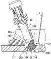
Fig. 3 is a cross-sectional view showing an example of a structure for fixing an optical fiber ferrule to a holder for polishing an optical fiber ferrule.
Fig. 4 is a cross-sectional view showing another example of a structure for fixing an optical fiber ferrule to a holder for polishing an optical fiber ferrule.
Fig. 5 is a cross-sectional view showing another example of a structure for fixing the optical fiber ferrule to the optical fiber ferrule polishing holder.
FIG. 6 is an enlarged plan view showing an example of the insertion hole of the holder for polishing an optical fiber ferrule.
FIG. 7 is an enlarged plan view showing another example of the insertion hole of the holder for polishing an optical fiber ferrule.
FIG. 8 is an enlarged plan view showing another example of the insertion hole of the holder for polishing an optical fiber ferrule.
FIG. 9 is an enlarged plan view showing another example of the insertion hole of the holder for polishing an optical fiber ferrule.
FIG. 10 is a conceptual diagram illustrating a structure of supporting an optical fiber ferrule in a conventional supporting member for polishing an optical fiber ferrule.
FIG. 11 is a conceptual diagram illustrating an optical fiber ferrule supporting structure in the optical fiber ferrule polishing support according to the present invention.
Reference numerals
10: an optical fiber ferrule grinding device; 11: rotating the arm; 12: a support member mounting portion; 13: grinding the surface; 20: a support for polishing an optical fiber ferrule; 21: a main body portion; 21A: a jack; 21A 1: a support wall; 21A 2: a side wall; 21A 3: a side wall; 21B: bolt holes; 21C: a protrusion; 22: a bolt; 23: a gasket; 24: a fastening member; 25: a movable part; 25A: an inclined surface; 25B: pressing the wall; 26: a spring; 27: a stopper; 28: a rod member; 28A: a shaft; 28B: an inclined surface; 29: a movable part; 29A: a shaft; 29B: pressing the wall; 29C: an inclined surface; 30: an optical fiber ferrule.
Detailed Description
Embodiments of the present invention are described below with reference to the drawings given as examples. FIG. 1 is a side view of the optical fiber ferrule polishing apparatus 10 with the optical fiber ferrule polishing support 20 attached. The optical fiber ferrule polishing apparatus 10 includes a swing arm 11, a holder mounting portion 12, and a polishing surface 13. The rotary arm 11 has the structure that: the polishing surface 13 is rotatable about a predetermined axis between a polishing position parallel to the polishing surface and an attaching/detaching position above the polishing surface. The support mounting portion 12 is provided on the opposite side of the shaft of the rotating arm 11. The holder mounting portion 12 has a structure in which the holder 20 for polishing the optical fiber ferrule can be attached and detached. As described later, the optical fiber ferrule polishing holder 20 has a structure for fixing the optical fiber ferrule 30.
When the optical fiber ferrule 30 is attached to or detached from the optical fiber ferrule polishing holder 20, the rotary arm 11 is set to the attached/detached position, and the optical fiber ferrule polishing holder 20 is detached from the optical fiber ferrule polishing apparatus 10. When polishing the optical fiber ferrule, the rotating arm 11 is rotated toward the polishing position in a state where the optical fiber ferrule polishing holder 20 is mounted on the optical fiber ferrule polishing apparatus 10, and the optical fiber ferrule polishing holder 20 is thereby brought close to the polishing surface 13. Accordingly, the end face of the optical fiber ferrule 30 protruding from the lower surface of the ferrule polishing holder 20 is polished by the polishing surface 13. The lower surface is a lower surface when the side surface of the insertion hole is a front surface. The details of the optical fiber ferrule polishing apparatus 10 will not be described in detail.
Fig. 2 is a plan view of the body portion 21 of the optical fiber ferrule polishing support 20. The main body 21 is formed in a circular plate shape. The main body 21 is formed with a plurality of insertion holes 21A into which the optical fiber ferrules 30 are inserted. The insertion holes 21A are arranged at regular intervals in a concentric circle shape substantially centering on the center of the body 21. Each insertion hole 21A penetrates the body portion 21 in the plate thickness direction. The details of the construction of each insertion hole 21A will be described later. A fixing structure for fixing the optical fiber ferrule 30 is disposed in each insertion hole 21A.
Fig. 3 is a cross-sectional view showing an example of a fixing structure for fixing the optical fiber ferrule 30 to the optical fiber ferrule polishing holder 20. The fixing structure is constituted by the main body portion 21, the bolt 22, the washer 23, the fastening member 24, the movable member 25, the spring 26, and the stopper 27. The bolt 22 is screwed to a bolt hole 21B provided in the main body 21. A washer 23 and a fastening member 24 are inserted between the bolt 22 and the body 21. The movable member 25 is disposed between the insertion hole 21A and the bolt hole 21B, and is movable along a predetermined path in the horizontal direction. The movable member 25 is urged in the upper surface direction of the body 21 by a spring 26. That is, the movable member 25 is urged in a direction to release the fixation of the optical fiber ferrule 30. The movable member 25 has an inclined surface 25A on the upper surface, the height of which gradually decreases from near the center toward the bolt hole 21B. One end of the fastening member 24 is disposed above the inclined surface 25A.
When the optical fiber ferrule 30 is inserted into the insertion hole 21A, the optical fiber ferrule 30 is interposed between the support wall 21A1 of the insertion hole 21A and the pressing wall 25B of the movable member 25. When the bolt 22 is fastened to the bolt hole 21B with the optical fiber ferrule 30 inserted into the insertion hole 21A, the bolt 22 presses the fastening member 24 downward via the washer 23. Accordingly, the one end of the fastening member 24 presses the inclined surface 25A downward. When the inclined surface 25A is pressed downward, the movable member 25 is pressed downward in the vertical direction against the biasing force of the spring 26, and is also pressed in the horizontal direction due to the inclined surface 25A. Accordingly, the optical fiber ferrule 30 is pressed against the support wall 21A1 with a predetermined pressure by the pressing wall 25B, and the optical fiber ferrule 30 is fixed to the insertion hole 21A. When the bolt 22 is loosened from the bolt hole 21B, the bolt 22 moves upward, and the downward pressing of the bolt 22 against the fastening member 2 is thereby released. Accordingly, the movable member 25 is released from being pressed by the tightening member 24, and the optical fiber ferrule 30 is released from being fixed by the biasing force of the spring 26. The stopper 27 restricts the movable member 25 from moving in a direction released above a given path. As described above, the optical fiber ferrule 30 can be pressed or released toward the support wall 21a1 with a given pressure by the movement of the movable member 25. In the foregoing fixing configuration, the given pressure can be adjusted by the degree of fastening of the bolt hole 21B by the bolt 22. In the present embodiment, the movable member 25 is a fixed portion, and the bolt 22, the washer 23, and the fastening member 24 are a bolt fastening structure.
When the optical fiber ferrule 30 is fixed to each insertion hole 21A, the tip of the optical fiber ferrule 30 slightly protrudes from the lower surface of the body 21. The optical fiber ferrule 30 is inclined at a predetermined angle θ with respect to a vertical axis extending perpendicularly from the lower surface of the main body 21. That is, when the optical fiber ferrule polishing apparatus 10 is equipped with the optical fiber ferrule polishing holder, the optical fiber ferrule 30 is inclined at a predetermined angle θ with respect to a vertical axis extending perpendicularly from the polishing surface 13. The given angle theta is typically 8 deg..
Fig. 4 and 5 are cross-sectional views showing another example of a fixing structure for fixing the optical fiber ferrule 30 to the optical fiber ferrule polishing holder 20. FIG. 4 shows the optical fiber ferrule 30 in a released state, and FIG. 5 shows the optical fiber ferrule 30 in a secured state. The fixed structure is composed of a main body portion 21, a lever member 28, and a movable member 29. The lever member 28 is disposed above the body 21 and is rotatable about a predetermined axis 28A relative to the body 21. The lever member 28 is configured to be movable between a standing position (1 st position) shown in fig. 4 and an inclined position (2 nd position) shown in fig. 5. The movable member 29 is disposed in the insertion hole 21A or a portion adjacent thereto, and has a structure rotatable about a predetermined axis 29A with respect to the main body 21. The movable member 29 has an inclined surface 29C on the upper surface. The inclined surface 29C is gradually lowered in height from the vicinity of the center toward the axis 29A side at the inclined position. An inclined surface 28B is provided at the lower end of the lever member 28. The inclined surface 28B is inclined in an inclined position to meet substantially in parallel with the inclined surface 29C. Accordingly, the inclined surface 28B does not contact the inclined surface 29C in the released state, but the inclined surface 28B contacts the inclined surface 29C and presses the inclined surface 29C in the fixed state. Although not shown, the movable member 29 is also urged by a spring in the upper surface direction of the main body 21, as in the fixed structure of fig. 3. That is, the movable member 29 is urged in a direction to release the fixation of the optical fiber ferrule 30.
When the optical fiber ferrule 30 is inserted into the insertion hole 21A, the optical fiber ferrule 30 is interposed between the support wall 21A1 of the insertion hole 21A and the pressing wall 29B of the movable member 29. When the lever member 28 is rotated from the upright position to the inclined position in a state where the optical fiber ferrule 30 is inserted into the insertion hole 21A, the inclined surface 28B of the lever member 28 presses the inclined surface 29C of the movable member 29 in the direction of the optical fiber ferrule 30. When the inclined surface 29C is pressed in the direction of the optical fiber ferrule 3O, the movable member 29 rotates clockwise about the shaft 29A against the urging force of the spring. Accordingly, the optical fiber ferrule 30 is pressed against the support wall 21A1 with a predetermined pressure by the pressing wall 29B, and the optical fiber ferrule 30 is fixed to the insertion hole 21A. When the lever member 28 is rotated from the inclined position to the upright position, the lever member 28 releases the pressing of the movable member 29, and the optical fiber ferrule 30 is released from being fixed by the biasing force of the spring. As described above, the movable member 29 is movable by the lever member 28, and when the lever member 28 is in the 1 st position, the movable member 29 presses the optical fiber ferrule 30 against the support wall 21a1, and when the lever member 28 is in the 2 nd position, the movable member 29 releases the optical fiber ferrule 30 from the support wall 21a 1. In the above-described fixed structure, the predetermined pressing force is set in advance in accordance with the positional relationship between the lever member 28 and the movable member 29, and the like. In the present embodiment, the movable member 29 belongs to the fixed portion.
When the optical fiber ferrule 30 is fixed to each insertion hole 21A, the tip of the optical fiber ferrule 30 slightly protrudes from the lower surface of the body 21. The optical fiber ferrule 30 is inclined at a predetermined angle θ with respect to a vertical axis extending perpendicularly from the lower surface of the main body 21. That is, when the optical fiber ferrule polishing apparatus 10 is equipped with the optical fiber ferrule polishing holder, the optical fiber ferrule 30 is inclined at a predetermined angle θ with respect to a vertical axis extending perpendicularly from the polishing surface 13. The given angle theta is typically 8 deg..
The configuration of the insertion hole 21A is explained below. The structure of the insertion hole 21A described below can be commonly applied to the holder 20 for polishing an optical fiber ferrule shown in fig. 3 and the holder 20 for polishing an optical fiber ferrule shown in fig. 4 and 5.
FIG. 6 is an enlarged plan view showing an example of the insertion hole 21A of the retainer 20 for polishing an optical fiber ferrule. The body 21 is provided with a plurality of insertion holes 21A. The substantially rectangular portion of the receptacle 21A bounded by the support wall 21A1 and the side walls 21A2, 21A3 is the portion for inserting the optical fiber ferrule 30. The remaining part of the insertion hole 21A is a part for arranging a fixing structure. As shown in fig. 6, a protrusion 21C is formed on the support wall 21a 1. Here, the support wall 21A1 is an inner wall of the insertion hole 21A that presses the opposite side surface of the optical fiber ferrule 30 when the pressing wall 25B of the movable member 25 presses one surface of the optical fiber ferrule 30. That is, the body 21 abuts the optical fiber ferrule 30 with the support wall 21A1 of the insertion hole 21A.
The protrusion 21C is a portion where a part of the support wall 21a1 protrudes toward the facing inner wall. As shown in fig. 11, in a state where the movable member 25(29) is disposed in the insertion hole 21A, the protruding portion 21C protrudes toward the pressing wall 25B (29B).
The protruding portion 21C protrudes at a given height H. The given height H is preferably in the range of 0.001mm to 0.026 mm. If the predetermined height H exceeds the upper limit of the above range, the roundness of the spherical surface shape of the end face of the optical fiber ferrule 30 after polishing becomes too small, which is not preferable. On the other hand, if the predetermined height H is less than the lower limit of the above range, the effect of the protrusion 21C cannot be sufficiently exhibited, which is not preferable.
The projection 21C is formed with a given width W2 occupied in the entire width W1 of the support wall 21a 1. In this example, the overall width W1 was set to 6.5mm, and the given width W2 was set to 2.0 mm. The W1 is set to be slightly wider than the width of the fiber optic ferrule 30. Accordingly, when the optical fiber ferrule 30 is inserted into the insertion hole 21A, the optical fiber ferrule 30 can be positioned by surrounding it with the support wall 21A1 and the side walls 21A2 and 21A 3. The given width W2 is preferably in the range of 0.5mm to 4.0 mm. If the predetermined width W2 exceeds the upper limit of the above range, the recess of the optical fiber ferrule 30 may be bent when pressed against the protrusion 21C, which is not preferable. On the other hand, if the predetermined width W2 is less than the lower limit of the above range, the effect of the protrusion 21C is not sufficiently exhibited, which is not preferable.
When viewed from above the ferrule polishing support 20, the protrusion 21C is preferably located at the center of the support wall 21a 1. Here, although the center is mentioned, it is not necessary that the distance between the center and both end portions of the support wall 21a1 is strictly equal. The protrusion 21C may be located near the center of the optical fiber ferrule 30 when the optical fiber ferrule 30 is inserted. In addition, the center of the protrusion 21C is not necessarily required to be at the center of the support wall 21a1, as long as a part of the protrusion 21C is at the center of the support wall 2TLA 1.
The protrusion 21C may be formed so as to protrude in the height H direction only at a part in the vertical direction of the support wall 21a 1. That is, the following structure can be made: the protrusion 21C is provided only at a position in contact with the optical fiber ferrule 30. On the other hand, the protruding portion 21C may also have a shape protruding in the height H direction over the entire up-down direction of the support wall 21a 1. The up-down direction means: the direction from the upper surface to the lower surface or the direction from the lower surface to the upper surface when the side surface of the jack is taken as the front surface. Further, the protruding portion 21C may be configured such that: formed in the same sectional shape from the upper side to the lower side.
FIG. 7 is an enlarged plan view showing another example of the insertion hole 21A of the holder 20 for polishing an optical fiber ferrule. As shown in FIG. 7, the surface of the protrusion 21C that contacts the optical fiber ferrule 30 may be recessed. The projecting portion 21C may be configured to project from the support wall 21a1 toward the pressing wall 25B (29B) as a whole. When the depth of the recess of the protruding portion 21C is approximately the same as the height H, the protruding portion 21C may have a structure including a plurality of narrow projections.
FIG. 8 is an enlarged plan view showing another example of the insertion hole 21A of the retainer 20 for polishing an optical fiber ferrule. As shown in fig. 8, the protrusion 21C may have an arc-shaped cross-sectional shape when viewed from above. The arc shape is not limited to a regular arc, but may be an elliptical arc or other rounded shape. The protrusion 21C may have various structures having a quadratic curve-like cross-sectional shape.
FIG. 9 is an enlarged plan view showing another example of the insertion hole 21A of the holder 20 for polishing an optical fiber ferrule. As shown in fig. 9, the protruding portion 21C may have an arc-like or quadratic curve-like cross-sectional shape gradually protruding from both ends of the support wall 21a 1. That is, if the protrusion 21C has an arc-shaped or quadratic curve-shaped cross section, the protrusion 21C can be formed along the entire width W1 of the support wall 21a 1. Note that, as in the case of the protrusion 21C shown in fig. 8 and 9, the surface area contacting the optical fiber ferrule 30 may be recessed as in the example shown in fig. 7.
Fig. 10 and 11 are conceptual views showing a support structure of the optical fiber ferrule 30. While no protrusion is formed in the conventional holder for polishing an optical fiber ferrule shown in fig. 10, a protrusion 21C is formed in the holder 20 for polishing an optical fiber ferrule shown in fig. 11. The case where the optical fiber ferrule 30 having a depressed central portion is fixed will be described as an example. In fig. 10 and 11, the shape and the like of the optical fiber ferrule 30 are depicted in a partially exaggerated manner for the purpose of facilitating understanding of the description.
As shown in fig. 10, in the conventional optical fiber ferrule polishing holder, when a depression is formed in the center of the optical fiber ferrule 30 and the pressing wall 25B (29B) of the movable member 25(29) presses the optical fiber ferrule 30 having a rectangular cross section, the depression of the optical fiber ferrule 30 is pressed until it substantially abuts against the support wall 21A, and the optical fiber ferrule 30 is bent. That is, the optical fiber ferrule 30 is curved in an arc shape when viewed from the top. If the optical fiber ferrule 30 is obliquely polished in a state where the optical fiber ferrule 30 is bent, there may be cases where: when the optical fiber ferrule polishing pad 20 is removed and the deflection disappears, the end face shape of the optical fiber ferrule 30 becomes a concave shape. Such a shape is not suitable for connection between optical fiber ferrules.
As shown in fig. 11, in the holder 20 for polishing an optical fiber ferrule according to the present invention, the support wall 21a1 is formed with a protrusion 21C, and the recess of the optical fiber ferrule 30 abuts against the protrusion 21C at a position just before the support wall 21a1 abuts. Thus, the fiber optic ferrule 30 does not flex any further. That is, before the optical fiber ferrule 30 is bent in an arc shape as viewed from above, the optical fiber ferrule 30 is held and fixed between the movable member 25(29) and the support wall 21a 1. Even if the optical fiber ferrule 30 is not recessed, the optical fiber ferrule 30 is held and fixed between the movable member 25(29) and the protruding portion 21C of the support wall 21a1, and the work is not affected. In the fixing structure shown in fig. 4 and 5, since the pressing force for fixing the optical fiber ferrule 30 by the pressing wall 29B is set to be constant in advance, the flexure can be suppressed even if the pressing force is constant. The configuration of the present invention is particularly effective when such a fixed configuration is employed.
Although the plurality of insertion holes 21A are arranged in a concentric circle shape substantially centering on the center of the body portion 21 in the above-described embodiment, the insertion holes 21A are not necessarily arranged in a concentric circle shape. The insertion holes 21A may be arranged in a straight line or a lattice shape or even in a random arrangement. In addition, the insertion holes 21A are not necessarily equally spaced from each other.
Although the structure for fixing the optical fiber ferrule 30 to the optical fiber ferrule polishing holder 20 in the above-described embodiment has been described by way of example of the fixing structure shown in fig. 3, 4, and 5, the fixing structure is not limited to these examples. The structure of the insertion hole 21A of the present invention can be applied to any structure that fixes an optical fiber ferrule having a rectangular cross section.
The shape of the projection 21C illustrated in the above embodiments is merely an example of the shape of the projection 21C. The shape of the protruding portion 21C may be other shapes as long as the protruding portion 21C protrudes toward the pressing wall 25B (29B).
Needless to say, the present invention is of course not limited to the above-described embodiments. To those skilled in the art, the following items are certainly disclosed as an embodiment of the present invention: the components and structures disclosed in the above embodiments that can be replaced with each other are appropriately changed and combined; members and structures which are not disclosed in the above embodiments but are known in the art and which are replaceable with each other and are combined with each other as appropriate; the present invention is applicable to a combination of components and structures that are not disclosed in the above embodiments but can be substituted for the components and structures disclosed in the above embodiments and the like by those skilled in the art based on the known techniques, by appropriately replacing them.
Claims (6)
1. A supporting member for polishing an optical fiber ferrule, which is mounted on an optical fiber ferrule polishing apparatus and used for APC polishing an optical fiber ferrule having a rectangular cross section, and which comprises a main body portion having an insertion hole into which the optical fiber ferrule is removably inserted and which is capable of abutting against the optical fiber ferrule via a supporting wall of the insertion hole, and a fixing portion having a pressing wall for pressing the optical fiber ferrule against the supporting wall with a predetermined pressure, wherein the supporting wall is inclined at a predetermined angle with respect to a vertical axis extending perpendicularly from a polishing surface of the optical fiber ferrule polishing apparatus; the support wall has a protruding portion facing the pressing wall.
2. The optical fiber ferrule polishing pad as claimed in claim 1, wherein the height of the protrusion is 0.001mm to 0.026 mm.
3. The optical fiber ferrule polishing support member according to claim 1 or 2, wherein said protrusion is located at the center of said support wall when viewed from above.
4. The optical fiber ferrule polishing support member according to claim 1, wherein said protrusion of said support wall has a cross-sectional shape of: when viewed from above, the shape of the arc or the quadratic curve is formed.
5. The optical fiber ferrule polishing support member according to any one of claims 1 to 4, wherein said fixed portion has a movable member movable along a given path by a bolt fastening structure, and said optical fiber ferrule is pressed or released toward said support wall with a given pressure by the movement of said movable member.
6. The holder for polishing an optical fiber ferrule according to any one of claims 1 to 4, wherein the fixing portion has a rod member movable between a1 st position and a2 nd position, and a movable member movable by the rod member, the movable member pressing the optical fiber ferrule against the support wall when the rod member is in the 1 st position, and the movable member releasing the optical fiber ferrule from the support wall when the rod member is in the 2 nd position.
Applications Claiming Priority (2)
| Application Number | Priority Date | Filing Date | Title |
|---|---|---|---|
| JP2019063350A JP6565015B1 (en) | 2019-03-28 | 2019-03-28 | Optical fiber ferrule polishing holder |
| JP2019-063350 | 2019-03-28 |
Publications (2)
| Publication Number | Publication Date |
|---|---|
| CN111745540A CN111745540A (en) | 2020-10-09 |
| CN111745540B true CN111745540B (en) | 2022-03-15 |
Family
ID=67766594
Family Applications (1)
| Application Number | Title | Priority Date | Filing Date |
|---|---|---|---|
| CN201911210876.8A Active CN111745540B (en) | 2019-03-28 | 2019-12-02 | Supporting member for polishing optical fiber ferrule |
Country Status (4)
| Country | Link |
|---|---|
| US (1) | US11571784B2 (en) |
| JP (1) | JP6565015B1 (en) |
| CN (1) | CN111745540B (en) |
| MX (1) | MX2020001440A (en) |
Families Citing this family (3)
| Publication number | Priority date | Publication date | Assignee | Title |
|---|---|---|---|---|
| US12271039B2 (en) | 2021-12-17 | 2025-04-08 | Domaille Engineering, Llc | Optical fiber polisher with controlled platen stopping position |
| WO2024070270A1 (en) * | 2022-09-27 | 2024-04-04 | 株式会社精工技研 | Jig for polishing optical fiber ferrule |
| CN120269458A (en) * | 2025-04-29 | 2025-07-08 | 泰兴市和宸晶体科技有限公司 | Equipment for precisely polishing inner cavity and outer cavity of hard and brittle material capillary tube |
Citations (6)
| Publication number | Priority date | Publication date | Assignee | Title |
|---|---|---|---|---|
| EP0705662B1 (en) * | 1994-10-07 | 2001-11-21 | SEIKOH GIKEN Co., Ltd. | Apparatus for polishing end surface of optical fibers |
| JP2003334750A (en) * | 2002-05-17 | 2003-11-25 | Asahi Glass Co Ltd | Optical fiber polishing jig and optical fiber polishing method |
| CN1506190A (en) * | 2002-12-06 | 2004-06-23 | 株式会社精工技研 | Support for optical fiber bearings ring end lapping apparatus |
| JP2010280016A (en) * | 2009-06-03 | 2010-12-16 | Japan Aviation Electronics Industry Ltd | Polishing jig, ferrule and optical connector |
| WO2017159675A1 (en) * | 2016-03-16 | 2017-09-21 | 株式会社精工技研 | Optical fiber ferrule polishing jig and mounting member |
| CN108747503A (en) * | 2018-08-02 | 2018-11-06 | 江苏君华光电科技有限公司 | Optical fiber splicer display/panel bracket machining fixing tool |
Family Cites Families (4)
| Publication number | Priority date | Publication date | Assignee | Title |
|---|---|---|---|---|
| JP2594613B2 (en) * | 1988-04-22 | 1997-03-26 | 住友電気工業株式会社 | Polishing method for end face of optical connector ferrule |
| JP3089352B2 (en) * | 1997-03-26 | 2000-09-18 | 株式会社エアロ・バッテリー・コーポレーション | Storage battery with protection device |
| JP2000343398A (en) * | 1999-06-03 | 2000-12-12 | Fujikura Ltd | Optical connector holding jig for optical connector polishing equipment |
| JP2011121129A (en) * | 2009-12-10 | 2011-06-23 | Sanwa Denki Kogyo Co Ltd | Polishing device of optical connector plug |
-
2019
- 2019-03-28 JP JP2019063350A patent/JP6565015B1/en active Active
- 2019-12-02 CN CN201911210876.8A patent/CN111745540B/en active Active
- 2019-12-02 US US16/699,734 patent/US11571784B2/en active Active
-
2020
- 2020-02-05 MX MX2020001440A patent/MX2020001440A/en unknown
Patent Citations (7)
| Publication number | Priority date | Publication date | Assignee | Title |
|---|---|---|---|---|
| EP0705662B1 (en) * | 1994-10-07 | 2001-11-21 | SEIKOH GIKEN Co., Ltd. | Apparatus for polishing end surface of optical fibers |
| JP2003334750A (en) * | 2002-05-17 | 2003-11-25 | Asahi Glass Co Ltd | Optical fiber polishing jig and optical fiber polishing method |
| CN1506190A (en) * | 2002-12-06 | 2004-06-23 | 株式会社精工技研 | Support for optical fiber bearings ring end lapping apparatus |
| JP2004181608A (en) * | 2002-12-06 | 2004-07-02 | Seikoh Giken Co Ltd | Polishing jig for ferrule end surface with optical fiber polishing machine |
| JP2010280016A (en) * | 2009-06-03 | 2010-12-16 | Japan Aviation Electronics Industry Ltd | Polishing jig, ferrule and optical connector |
| WO2017159675A1 (en) * | 2016-03-16 | 2017-09-21 | 株式会社精工技研 | Optical fiber ferrule polishing jig and mounting member |
| CN108747503A (en) * | 2018-08-02 | 2018-11-06 | 江苏君华光电科技有限公司 | Optical fiber splicer display/panel bracket machining fixing tool |
Also Published As
| Publication number | Publication date |
|---|---|
| JP6565015B1 (en) | 2019-08-28 |
| MX2020001440A (en) | 2020-09-29 |
| US20200306926A1 (en) | 2020-10-01 |
| CN111745540A (en) | 2020-10-09 |
| JP2020163475A (en) | 2020-10-08 |
| US11571784B2 (en) | 2023-02-07 |
Similar Documents
| Publication | Publication Date | Title |
|---|---|---|
| CN111745540B (en) | Supporting member for polishing optical fiber ferrule | |
| JP5836382B2 (en) | Clamping device with independent elastic clamp fingers for attaching the cutting tip to the tool holder | |
| US7542648B2 (en) | Holder for optical fiber ferrule end face grinding apparatus | |
| JP5361543B2 (en) | Polishing jig, ferrule and optical connector | |
| JP4074812B2 (en) | Polishing jig for ferrule end polishing machine with optical fiber | |
| US9748731B2 (en) | Optical apparatus | |
| JP4728305B2 (en) | Clip type inspection jig and clip open state holding mechanism used therefor | |
| CN115446727A (en) | Supporting member for polishing optical fiber ferrule and optical fiber ferrule polishing apparatus | |
| JP4541215B2 (en) | Centering and positioning device for mounting a fuel injector on a gas turbine engine | |
| US8878084B2 (en) | Movable contact holder | |
| JP4394306B2 (en) | Optical pickup guide device | |
| JP4099436B2 (en) | Optical connector | |
| JP6620071B2 (en) | Wiper blade | |
| JP6581478B2 (en) | Wire spring retainer, rail fastening device | |
| JP6359467B2 (en) | Liquid crystal display | |
| TWI356209B (en) | Lens holder | |
| CN116867685A (en) | Bracket | |
| JP7842801B2 (en) | Device for handling test contacts | |
| TW202108977A (en) | Holder and measuring jig capable of easily holding an object to be held such as a lens | |
| JP3565473B2 (en) | Display panel inspection socket | |
| JP2017119347A (en) | Holder joint | |
| JP7284535B1 (en) | Equipment for polishing the end faces of optical fiber ferrules, offset rings used for equipment for polishing the end faces of optical fiber ferrules | |
| JP4888036B2 (en) | Auxiliary storage device mounting device | |
| JP2004022270A (en) | Connector mounting structure for electronic equipment | |
| JP3238252B2 (en) | Positioning key for optical connector ferrule |
Legal Events
| Date | Code | Title | Description |
|---|---|---|---|
| PB01 | Publication | ||
| PB01 | Publication | ||
| SE01 | Entry into force of request for substantive examination | ||
| SE01 | Entry into force of request for substantive examination | ||
| GR01 | Patent grant | ||
| GR01 | Patent grant |