CN111761871A - A paper cup die-cutting machine - Google Patents
A paper cup die-cutting machine Download PDFInfo
- Publication number
- CN111761871A CN111761871A CN202010596443.7A CN202010596443A CN111761871A CN 111761871 A CN111761871 A CN 111761871A CN 202010596443 A CN202010596443 A CN 202010596443A CN 111761871 A CN111761871 A CN 111761871A
- Authority
- CN
- China
- Prior art keywords
- die
- paper
- cutting
- plate
- collecting box
- Prior art date
- Legal status (The legal status is an assumption and is not a legal conclusion. Google has not performed a legal analysis and makes no representation as to the accuracy of the status listed.)
- Granted
Links
Images



Classifications
-
- B—PERFORMING OPERATIONS; TRANSPORTING
- B31—MAKING ARTICLES OF PAPER, CARDBOARD OR MATERIAL WORKED IN A MANNER ANALOGOUS TO PAPER; WORKING PAPER, CARDBOARD OR MATERIAL WORKED IN A MANNER ANALOGOUS TO PAPER
- B31B—MAKING CONTAINERS OF PAPER, CARDBOARD OR MATERIAL WORKED IN A MANNER ANALOGOUS TO PAPER
- B31B50/00—Making rigid or semi-rigid containers, e.g. boxes or cartons
- B31B50/14—Cutting, e.g. perforating, punching, slitting or trimming
- B31B50/20—Cutting sheets or blanks
-
- B—PERFORMING OPERATIONS; TRANSPORTING
- B31—MAKING ARTICLES OF PAPER, CARDBOARD OR MATERIAL WORKED IN A MANNER ANALOGOUS TO PAPER; WORKING PAPER, CARDBOARD OR MATERIAL WORKED IN A MANNER ANALOGOUS TO PAPER
- B31B—MAKING CONTAINERS OF PAPER, CARDBOARD OR MATERIAL WORKED IN A MANNER ANALOGOUS TO PAPER
- B31B50/00—Making rigid or semi-rigid containers, e.g. boxes or cartons
- B31B50/74—Auxiliary operations
Landscapes
- Control And Other Processes For Unpacking Of Materials (AREA)
- Making Paper Articles (AREA)
Abstract
本发明公开了一种纸杯模切机,涉及纸杯加工领域,解决了现有技术中纸杯加工效率低的问题,其技术要点是:包括底座,底座的上方设有压板,压板上固定连接用于切纸的模切单元,底座内还设有用于驱动压板上下移动的压板驱动单元,所述模切单元包括模具刀和刀框,所述模具刀由多组两端设有开口的切管组成,所述切管的截面与纸杯所切部分形状相同,模具刀固定连接在刀框内,模具刀上的切管内还套设有用于收集纸杯所切部分的集纸盒,集纸盒能够从模切单元上拆卸;本发明通过集纸盒在切纸时收集纸杯所切部分,省却了人工收集纸杯所切部分的步骤,提高了纸杯所切部分整理效率。
The invention discloses a paper cup die-cutting machine, which relates to the field of paper cup processing and solves the problem of low processing efficiency of paper cups in the prior art. A die-cutting unit for paper cutting, the base is also provided with a platen drive unit for driving the platen to move up and down, the die-cutting unit includes a die-cutting knife and a knife frame, and the die-cutting knife is composed of multiple sets of cutting tubes with openings at both ends , the section of the cutting tube is the same as the shape of the cut part of the paper cup, the die knife is fixedly connected in the knife frame, and the cutting tube on the die knife is also sleeved with a collecting box for collecting the cut part of the paper cup. The die-cutting unit is disassembled; the present invention collects the cut parts of the paper cups through the paper collecting box when cutting paper, saves the step of manually collecting the cut parts of the paper cups, and improves the sorting efficiency of the cut parts of the paper cups.
Description
技术领域technical field
本发明涉及纸杯加工领域,尤其涉及一种纸杯模切机。The invention relates to the field of paper cup processing, in particular to a paper cup die-cutting machine.
背景技术Background technique
一次性纸杯是一种方便携带和使用,价格低廉的纸质杯子,是许多家庭和公共场所常见的喝水工具。Disposable paper cups are paper cups that are easy to carry, use, and inexpensive, and are common drinking tools in many homes and public places.
在一次性纸杯加工过程中需要使用到模切机,将纸杯原料切成预设形状。模切机的工作原理是利用模切刀、钢刀、五金模具、钢线,通过压印版施加一定的压力,将印品或纸板轧切成一定形状。During the processing of disposable paper cups, a die-cutting machine is required to cut the raw materials of paper cups into preset shapes. The working principle of the die-cutting machine is to use die-cutting knives, steel knives, metal molds, and steel wires to apply a certain pressure through the embossing plate to cut the printed product or cardboard into a certain shape.
现有技术中纸杯模切机在切纸时通常将纸杯部分切出部分轮廓,使得纸杯部分仍然与原料纸连带,再将原料纸切成较大的部分以方便整理,卷制纸杯时,将纸杯部分扣掉后送入卷筒机卷制纸杯,使得纸杯的加工效率较低,因此,我们提出了一种纸杯模切机。In the prior art, the paper cup die-cutting machine usually cuts out part of the outline of the paper cup part when cutting paper, so that the paper cup part is still associated with the raw material paper, and then the raw material paper is cut into larger parts to facilitate sorting. The paper cup part is deducted and then sent to the reel machine to roll the paper cup, which makes the processing efficiency of the paper cup low. Therefore, we propose a paper cup die-cutting machine.
发明内容SUMMARY OF THE INVENTION
本发明要解决的技术问题是针对上述缺陷,提供一种纸杯模切机,包括底座,底座的上方设有压板,压板上固定连接用于切纸的模切单元,底座内还设有用于驱动压板上下移动的压板驱动单元,所述模切单元包括模具刀和刀框,所述模具刀由多组两端设有开口的切管组成,所述切管的截面与纸杯所切部分形状相同,模具刀固定连接在刀框内,模具刀上的切管内还套设有用于收集纸杯所切部分的集纸盒,集纸盒能够从模切单元上拆卸,以解决现有技术中纸杯加工效率低的问题。The technical problem to be solved by the present invention is to provide a paper cup die-cutting machine in view of the above-mentioned defects, which includes a base, a pressing plate is arranged above the base, a die-cutting unit for cutting paper is fixedly connected to the pressing plate, and a driving unit is also provided in the base for driving A platen drive unit that moves up and down the platen, the die-cutting unit includes a die knife and a knife frame, the die-cutting knife is composed of multiple sets of cutting tubes with openings at both ends, and the section of the cutting tubes is the same as the shape of the part cut by the paper cup , the mold knife is fixedly connected in the knife frame, and the cutting tube on the mold knife is also sleeved with a paper collecting box for collecting the cut part of the paper cup. problem of inefficiency.
为实现上述目的,本发明提供如下技术方案:To achieve the above object, the present invention provides the following technical solutions:
一种纸杯模切机,包括底座,底座的上方设有压板,压板上固定连接用于切纸的模切单元,底座内还设有用于驱动压板上下移动的压板驱动单元,所述模切单元包括模具刀和刀框,所述模具刀由多组两端设有开口的切管组成,所述切管的截面与纸杯所切部分形状相同,模具刀固定连接在刀框内,模具刀上的切管内还套设有用于收集纸杯所切部分的集纸盒,集纸盒能够从模切单元上拆卸。A paper cup die-cutting machine includes a base, a pressure plate is arranged above the base, a die-cutting unit for cutting paper is fixedly connected to the pressure plate, and a pressure-plate driving unit for driving the pressure plate to move up and down is also arranged in the base, the die-cutting unit Including a die knife and a knife frame, the die knife is composed of a plurality of sets of cutting tubes with openings at both ends, the section of the cutting tube is the same as the shape of the part cut by the paper cup, the die knife is fixedly connected in the knife frame, and the die knife is on the The cutting tube is also sleeved with a collecting box for collecting the cut part of the paper cup, and the collecting box can be disassembled from the die-cutting unit.
作为本发明进一步的方案,底座上端设有模切板,模切板金属板,模切板上靠近压板的一面为光滑面,且光滑面的四边均为圆角。As a further solution of the present invention, the upper end of the base is provided with a die-cutting plate, a metal plate of the die-cutting plate, and the side of the die-cutting plate close to the pressing plate is a smooth surface, and the four sides of the smooth surface are rounded.
作为本发明进一步的方案,所述集纸盒为一端设有开口的筒状,集纸盒的外壁形状与模具刀内切管的内壁形状相同;集纸盒的口部还设有内倒角。As a further solution of the present invention, the paper collecting box is a cylindrical shape with an opening at one end, and the shape of the outer wall of the collecting box is the same as the shape of the inner wall of the inner-cut tube of the die knife; the mouth of the paper collecting box is also provided with an inner chamfer. .
作为本发明进一步的方案,集纸盒在靠近口部的外壁上设有限位条。As a further solution of the present invention, a limiting strip is provided on the outer wall of the paper collecting box near the mouth.
作为本发明进一步的方案,推纸杆靠近集纸盒口部的一端设有推板,所述推板的形状与集纸盒内壁的形状相同;推纸杆远离推纸板的一端穿过集纸盒与集纸盒滑动连接。As a further solution of the present invention, one end of the paper push rod close to the mouth of the paper collection box is provided with a push plate, and the shape of the push plate is the same as that of the inner wall of the paper collection box; the end of the paper push rod away from the push plate passes through the paper collection The box is slidably connected to the collection box.
作为本发明进一步的方案,所述压板驱动单元包括支撑板、连杆和压簧,支撑板设在驱动腔内,支撑板为平板,支撑板的两端分别固定连接到支撑板和压板上,压簧套设在连杆上,且压簧的两端分别与底座的内壁和压簧接触,支撑板的下端固定连接有用于间歇性推动支撑板上升的驱动组件,驱动组件固定连接到底座的底部。As a further solution of the present invention, the pressure plate driving unit includes a support plate, a connecting rod and a pressure spring, the support plate is arranged in the drive cavity, the support plate is a flat plate, and both ends of the support plate are fixedly connected to the support plate and the pressure plate respectively, The compression spring is sleeved on the connecting rod, and the two ends of the compression spring are in contact with the inner wall of the base and the compression spring respectively. bottom.
作为本发明进一步的方案,支撑板的底部还是设有导向杆,导向杆的外侧套设有导向管,导向管固定连接到底座的底部。As a further solution of the present invention, the bottom of the support plate is still provided with a guide rod, the outer side of the guide rod is sleeved with a guide tube, and the guide tube is fixedly connected to the bottom of the base.
综上所述,本发明与现有技术相比具有以下有益效果:To sum up, the present invention has the following beneficial effects compared with the prior art:
本发明通过集纸盒在切纸时收集纸杯所切部分,省却了人工收集纸杯所切部分的步骤,提高了纸杯所切部分整理效率,同时本发明能够增加单次切纸的数量,提高了模切机的切纸效率,相对于现有技术,本发明能够提高纸杯生产的效率。The present invention collects the cut part of the paper cup by the collecting box when cutting paper, saves the step of manually collecting the cut part of the paper cup, improves the sorting efficiency of the cut part of the paper cup, and at the same time, the invention can increase the number of single cutting paper, improve Compared with the prior art, the paper cutting efficiency of the die-cutting machine can improve the paper cup production efficiency.
附图说明Description of drawings
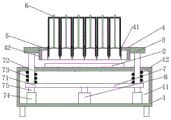
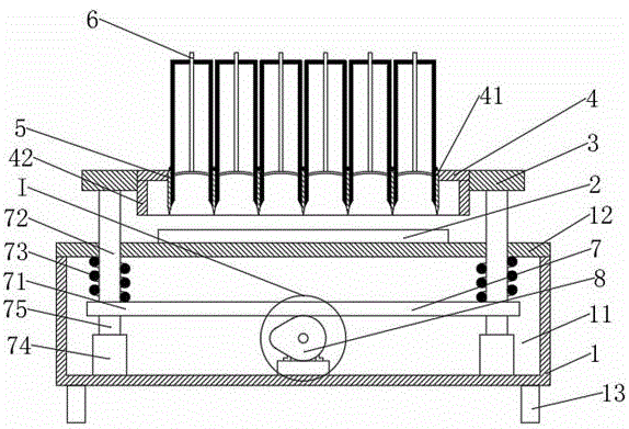
图1为纸杯模切机实施例1的结构示意图。FIG. 1 is a schematic structural diagram of
图2为图1中I处的局部放大图。FIG. 2 is a partial enlarged view of I in FIG. 1 .
图3为纸杯模切机中模切单元的结构示意图。Figure 3 is a schematic structural diagram of a die-cutting unit in a paper cup die-cutting machine.
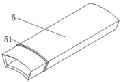
图4为纸杯模切机中集纸盒的结构示意图。FIG. 4 is a schematic structural diagram of a paper collecting box in a paper cup die-cutting machine.
图5为纸杯模切机中推纸杆的结构示意图。FIG. 5 is a schematic structural diagram of a paper push rod in a paper cup die-cutting machine.
图6为纸杯模切机实施例2的结构示意图。6 is a schematic structural diagram of
附图标记:1-底座,11-驱动腔,12-上盖,13-支撑脚,2-模切板,3-压板,4-模切单元,41-模具刀,42-刀框,5-集纸盒,51-限位条,6-推纸杆,7-压板驱动单元,71-支撑板,72-连杆,73-压簧,74-导向管,75-导向杆,8-驱动组件,81-驱动电机,82-凸轮。Reference numerals: 1-base, 11-drive cavity, 12-upper cover, 13-support foot, 2-die-cutting plate, 3-pressing plate, 4-die-cutting unit, 41-die knife, 42-knife frame, 5 -Paper tray, 51-Limit bar, 6-Paper lever, 7-Press plate drive unit, 71-Support plate, 72-Link, 73-Pressure spring, 74-Guide tube, 75-Guide rod, 8- Drive assembly, 81-drive motor, 82-cam.
具体实施方式Detailed ways
下面将结合本发明实施例中的附图,对本发明实施例中的技术方案进行清楚、完整地描述,显然,所描述的实施例仅仅是本发明一部分实施例,而不是全部的实施例,基于本发明中的实施例,本领域普通技术人员在没有做出创造性劳动前提下所获得的所有其他实施例,都属于本发明保护的范围。The technical solutions in the embodiments of the present invention will be clearly and completely described below with reference to the accompanying drawings in the embodiments of the present invention. Obviously, the described embodiments are only a part of the embodiments of the present invention, not all of the embodiments. The embodiments of the present invention, and all other embodiments obtained by those of ordinary skill in the art without creative work, fall within the protection scope of the present invention.
实施例1Example 1
由图1~图3所示,一种纸杯模切机,包括底座1,底座1的上方设有压板3,压板3上固定连接用于切纸的模切单元4,底座1内还设有用于驱动压板3上下移动的压板驱动单元7,模切单元4包括模具刀41和刀框42,所述模具刀41由多组两端设有开口的切管组成,所述切管的截面与纸杯所切部分形状相同,模具刀41固定连接在刀框42内,模具刀41上的切管内还套设有用于收集纸杯所切部分的集纸盒5,集纸盒5能够从模切单元4上拆卸;As shown in Figures 1 to 3, a paper cup die-cutting machine includes a
所述底座1内设有驱动腔11,驱动腔11在底座1的上端设有口部,驱动腔11的口部设有上盖12,上盖12通过螺钉固定连接到底座1上,压板驱动单元7设在驱动腔11内,所述上盖12的设置使得压板驱动单元7便于安装到底座1 的内部;The
底座1的底部还设有支撑脚13;The bottom of the
优选的,上盖12上还设有模切板2,模切板2金属板,模切板2上靠近压板3的一面为光滑面,且光滑面的四边均为圆角,从而防止模切板2刮花纸杯原料,且减小模切板2与纸杯原料之间的摩擦力,当压板3向下移动时,模切板2与模具刀41挤压纸杯原料,模具刀41将纸杯原料切成多组单个纸杯的大小,从而完成纸杯原料的模切工作;Preferably, the upper cover 12 is further provided with a die-
所述压板3方形块,压板3固定连接到模切单元4的侧面,压板3用于连接压板驱动单元7与模切单元4,在一些示例中,压板3通过螺钉固定连接到模切单元4上,且压板3通过螺钉与压板驱动单元7固定连接,压板3设有四组,且压板3设在模切单元4的两侧,工作时,压板驱动单元7驱动压板3上下移动;The
优选的,模具刀41在靠近底座1的一端开有刀刃,从而使得纸杯的切口整齐且能够快速切断纸杯原料;Preferably, the
如图4所示,所述集纸盒5为一端设有开口的筒状,集纸盒5的外壁形状与模具刀41内切管的内壁形状相同,从而使得纸杯所切部分能够进入集纸盒5内,当纸杯原料被模具刀41切断后,纸杯所切部分被压进集纸盒5内,由于集纸盒5设在模具刀41内,集纸盒5的内径小于纸杯所切部分的边缘,纸杯所切部分卡在集纸盒5内,随着模切工作的进行,集纸盒5内的纸杯所切部分堆叠在集纸盒5内,当集纸盒5内的纸杯所切部分满后,使用推纸杆6将纸杯所切部分推出;As shown in FIG. 4 , the
优选的,集纸盒5的口部还设有内倒角,从而防止纸杯所切部分卡在集纸盒5的口部,且集纸盒5口部的内倒角能够防止集纸盒5的口部对纸杯所切部分产生压痕;Preferably, the mouth of the
优选的,集纸盒5在靠近口部的外壁上设有限位条51,限位条51用于限制集纸盒5插入模具刀41内的长度,在一些示例中,所述限位条51为方形凸起;Preferably, a
如图5所示,推纸杆6为圆杆,推纸杆6靠近集纸盒5口部的一端设有推板,所述推板的形状与集纸盒5内壁的形状相同,推纸杆6能够将集纸盒5收集到的纸杯所切部分从集纸盒5内推出,推纸杆6远离推纸板的一端穿过集纸盒5与集纸盒5滑动连接,当集纸盒5内的纸杯所切部分满后,推动推纸杆6,推纸杆6能够将纸杯所切部分推出;As shown in FIG. 5 , the
所述压板驱动单元7包括,支撑板71、连杆72和压簧73,支撑板71设在驱动腔11内,支撑板71为平板,支撑板71的两端分别固定连接到支撑板71和压板3上,压簧73套设在连杆72上,且压簧73的两端分别与底座1的内壁和压簧73接触,驱动组件8固定连接到底座1的底部,且驱动组件8能够间歇性推动压簧73向上移动;当驱动组件8推动支撑板71向上移动时,压簧73压缩,支撑板71将压板3抬起,当驱动组件8停止推动支撑板71上,支撑板71在压簧73的作用下向下移动,从而带动压板3向下移动,压板3带动模切单元4完成切纸工作,压板驱动单元7的设置通过单个驱动单元推动压板3的上下运动,使得压板3的运行更加稳定;The
优选的,支撑板71的底部还是设有导向杆75,导向杆75的外侧套设有导向管74,导向管74固定连接到底座1的底部,导向管74和导向杆75用于对压板驱动单元7限位,使得压板驱动单元7能够上下移动;Preferably, the bottom of the
所述驱动组件8包括驱动电机81和凸轮82,驱动电机81固定连接到底座1的底部,凸轮82固定连接到驱动电机81的输出轴上,当驱动电机81转动时,驱动电机81带动凸轮82转动,凸轮82的偏心部推动支撑板71向上移动,当凸轮82的逐渐从偏心部转动到基圆部时,支撑板71在压簧73的作用下向下移动,从而使得凸轮82能够间歇性推动压簧73向上移动。The
实施例2Example 2
由图3~图5所示,一种纸杯模切机,包括底座1,底座1的上方设有压板3,压板3上固定连接用于切纸的模切单元4,底座1内还设有用于驱动压板3上下移动的压板驱动单元7,模切单元4包括模具刀41和刀框42,所述模具刀41由多组两端设有开口的切管组成,所述切管的截面与纸杯所切部分形状相同,模具刀41固定连接在刀框42内,模具刀41上的切管内还套设有用于收集纸杯所切部分的集纸盒5,集纸盒5能够从模切单元4上拆卸;As shown in Figures 3 to 5, a paper cup die-cutting machine includes a
本实施例中,驱动组件8为气缸,当驱动组件8内通入高压空气时,驱动组件8的活塞杆伸出,驱动组件8将压簧73顶起,当驱动组件8泄压时,支撑板71在压簧73的作用下向下移动,支撑板71带动压板3向下移动,压板3带动模切单元4完成切纸工作;In this embodiment, the
本实施例中其他结构与实施例1相同。Other structures in this embodiment are the same as those in
综上所述,本发明的工作原理是:To sum up, the working principle of the present invention is:
模切单元4在切纸时按照完整的轮廓将纸杯所切部分切除,纸杯所切部分卡设集纸盒5内,由于模切单元4内的切管可以设置多排,使得单次切纸数量增多,增加了切纸的效率,集纸盒5的内壁形状与纸杯所切部分形状相同,使得集纸盒5能够起到整理纸杯所切部分的作用,从而使得纸杯所切部分能够整齐的排列在集纸盒5内,省却了整理纸杯所切部分的工作,且省去了将纸杯所切部分从原料纸上取下的步骤,提高了生产效率;The die-cutting
纸杯所切部分进入集纸盒5时会将推纸杆6向集纸盒5的内部压,使得推纸杆6向集纸盒5的内部移动,当集纸盒5内的纸杯所切部分堆满时,将集纸盒5取出,然后推动推纸杆6即可将纸杯所切部分推出。When the cut part of the paper cup enters the
尽管已经示出和描述了本发明的实施例,对于本领域的普通技术人员而言,可以理解在不脱离本发明的原理和精神的情况下可以对这些实施例进行多种变化、修改、替换和变型,本发明的范围由所附权利要求及其等同物限定。Although embodiments of the present invention have been shown and described, it will be understood by those skilled in the art that various changes, modifications, and substitutions can be made in these embodiments without departing from the principle and spirit of the invention and modifications, the scope of the present invention is defined by the appended claims and their equivalents.
Claims (7)
Priority Applications (1)
| Application Number | Priority Date | Filing Date | Title |
|---|---|---|---|
| CN202010596443.7A CN111761871B (en) | 2020-06-28 | 2020-06-28 | Paper cup die-cutting machine |
Applications Claiming Priority (1)
| Application Number | Priority Date | Filing Date | Title |
|---|---|---|---|
| CN202010596443.7A CN111761871B (en) | 2020-06-28 | 2020-06-28 | Paper cup die-cutting machine |
Publications (2)
| Publication Number | Publication Date |
|---|---|
| CN111761871A true CN111761871A (en) | 2020-10-13 |
| CN111761871B CN111761871B (en) | 2022-03-18 |
Family
ID=72722294
Family Applications (1)
| Application Number | Title | Priority Date | Filing Date |
|---|---|---|---|
| CN202010596443.7A Active CN111761871B (en) | 2020-06-28 | 2020-06-28 | Paper cup die-cutting machine |
Country Status (1)
| Country | Link |
|---|---|
| CN (1) | CN111761871B (en) |
Cited By (1)
| Publication number | Priority date | Publication date | Assignee | Title |
|---|---|---|---|---|
| CN120191079A (en) * | 2025-05-26 | 2025-06-24 | 江苏凯序金原纸塑包装有限公司 | A paper cup die cutting machine |
Citations (7)
| Publication number | Priority date | Publication date | Assignee | Title |
|---|---|---|---|---|
| EP0100016A2 (en) * | 1982-07-17 | 1984-02-08 | Tetra Laval Holdings & Finance SA | Opening device for a parallelepiped package for a flowable material |
| CN202805733U (en) * | 2012-02-21 | 2013-03-20 | 瑞安市胜利机械有限公司 | Knife mold for cutting cup bottom of high speed dixie cup machine |
| CN106739138A (en) * | 2016-12-08 | 2017-05-31 | 滁州源远纸制品有限公司 | A kind of perforation borehole cleaning integration apparatus for carton production |
| CN209175907U (en) * | 2018-12-13 | 2019-07-30 | 南京冠佳科技有限公司 | Die-cutting mechanism of a die-cutting machine |
| CN209832768U (en) * | 2019-04-17 | 2019-12-24 | 佛山市南嘉包装科技有限公司 | Carton cutting device |
| CN210850606U (en) * | 2019-11-08 | 2020-06-26 | 昆山华卓昌精密模具有限公司 | Control panel punching die |
| CN210847961U (en) * | 2019-10-17 | 2020-06-26 | 杭州宇扬精密钣金有限公司 | Sheet metal stamping die with ejection device |
-
2020
- 2020-06-28 CN CN202010596443.7A patent/CN111761871B/en active Active
Patent Citations (8)
| Publication number | Priority date | Publication date | Assignee | Title |
|---|---|---|---|---|
| EP0100016A2 (en) * | 1982-07-17 | 1984-02-08 | Tetra Laval Holdings & Finance SA | Opening device for a parallelepiped package for a flowable material |
| JPS5937142A (en) * | 1982-07-17 | 1984-02-29 | テトラ・パツク・デヴエロプマン・ソシエテ・アノニム | Device for opening a parallelepiped package or carton for filling with fluid, and its manufacturing device |
| CN202805733U (en) * | 2012-02-21 | 2013-03-20 | 瑞安市胜利机械有限公司 | Knife mold for cutting cup bottom of high speed dixie cup machine |
| CN106739138A (en) * | 2016-12-08 | 2017-05-31 | 滁州源远纸制品有限公司 | A kind of perforation borehole cleaning integration apparatus for carton production |
| CN209175907U (en) * | 2018-12-13 | 2019-07-30 | 南京冠佳科技有限公司 | Die-cutting mechanism of a die-cutting machine |
| CN209832768U (en) * | 2019-04-17 | 2019-12-24 | 佛山市南嘉包装科技有限公司 | Carton cutting device |
| CN210847961U (en) * | 2019-10-17 | 2020-06-26 | 杭州宇扬精密钣金有限公司 | Sheet metal stamping die with ejection device |
| CN210850606U (en) * | 2019-11-08 | 2020-06-26 | 昆山华卓昌精密模具有限公司 | Control panel punching die |
Cited By (2)
| Publication number | Priority date | Publication date | Assignee | Title |
|---|---|---|---|---|
| CN120191079A (en) * | 2025-05-26 | 2025-06-24 | 江苏凯序金原纸塑包装有限公司 | A paper cup die cutting machine |
| CN120191079B (en) * | 2025-05-26 | 2026-02-06 | 江苏凯序金原纸塑包装有限公司 | A paper cup die-cutting machine |
Also Published As
| Publication number | Publication date |
|---|---|
| CN111761871B (en) | 2022-03-18 |
Similar Documents
| Publication | Publication Date | Title |
|---|---|---|
| CN111761871A (en) | A paper cup die-cutting machine | |
| CN112676421B (en) | A circular steel sheet stamping equipment for steel processing | |
| CN208099159U (en) | A precision juicer tool processing device for sheet metal stamping | |
| CN115026903B (en) | Drop production conveyor that punches | |
| CN108146026B (en) | A kind of creasing and cutting machine | |
| CN109318530A (en) | A kind of carton die cutting machine easy to use | |
| CN112497334A (en) | Corrugated paper perforating device | |
| CN221737227U (en) | Carton punching device | |
| CN201143105Y (en) | A gluing slitting and forming device | |
| CN217072474U (en) | Cutting device is used in eraser production | |
| CN110901160A (en) | Packaging paperboard slotting device | |
| CN209257583U (en) | A kind of stupefied molding guillotine of carton board pressure | |
| CN222536037U (en) | A cutting die for preventing material from getting stuck | |
| CN201769223U (en) | Filter core forming equipment for humidifier, die cutting device and material returning device | |
| CN117863285A (en) | A corrugated cardboard circular die-cutting device | |
| CN223478429U (en) | Cup bottom continuous feeding and cutting mechanism of paper cup machine | |
| CN220807717U (en) | Laminating pressure adjustable rotary die cutting machine | |
| CN220447310U (en) | Cutting device for packaging box packaging | |
| CN221912339U (en) | Aluminum foil punching machine | |
| CN221697095U (en) | Packaging paperboard cutting machine | |
| CN207643521U (en) | A kind of device for the excision of moulding flash | |
| CN215511205U (en) | Efficient die cutting device for label preparation | |
| CN217455124U (en) | A separate machine for wrapping bag production | |
| CN216180838U (en) | A kind of cutting device for traditional Chinese medicine processing | |
| CN219582936U (en) | Medicinal material slicer |
Legal Events
| Date | Code | Title | Description |
|---|---|---|---|
| PB01 | Publication | ||
| PB01 | Publication | ||
| SE01 | Entry into force of request for substantive examination | ||
| SE01 | Entry into force of request for substantive examination | ||
| GR01 | Patent grant | ||
| GR01 | Patent grant | ||
| CP01 | Change in the name or title of a patent holder | ||
| CP01 | Change in the name or title of a patent holder |
Address after: Ma Miao Zhen Wang Yang Lu, Huaining County, Anqing City, Anhui Province Patentee after: Anqing Qianqian Technology Packaging Co.,Ltd. Address before: Ma Miao Zhen Wang Yang Lu, Huaining County, Anqing City, Anhui Province Patentee before: ANQING QIANQIAN PAPER CO.,LTD. |
|
| EE01 | Entry into force of recordation of patent licensing contract |
Application publication date: 20201013 Assignee: Anhui Ruike Environmental Protection Technology Co.,Ltd. Assignor: Anqing Qianqian Technology Packaging Co.,Ltd. Contract record no.: X2023980043237 Denomination of invention: A paper cup die-cutting machine Granted publication date: 20220318 License type: Common License Record date: 20231017 |
|
| EE01 | Entry into force of recordation of patent licensing contract | ||
| PE01 | Entry into force of the registration of the contract for pledge of patent right |
Denomination of invention: A paper cup die-cutting machine Granted publication date: 20220318 Pledgee: Agricultural Bank of China Limited Huaining County sub branch Pledgor: Anqing Qianqian Technology Packaging Co.,Ltd. Registration number: Y2024980036974 |
|
| PE01 | Entry into force of the registration of the contract for pledge of patent right | ||
| PC01 | Cancellation of the registration of the contract for pledge of patent right |
Granted publication date: 20220318 Pledgee: Agricultural Bank of China Limited Huaining County sub branch Pledgor: Anqing Qianqian Technology Packaging Co.,Ltd. Registration number: Y2024980036974 |
|
| PC01 | Cancellation of the registration of the contract for pledge of patent right |