CN111761875A - Rolling assembly - Google Patents
Rolling assembly Download PDFInfo
- Publication number
- CN111761875A CN111761875A CN201910928963.0A CN201910928963A CN111761875A CN 111761875 A CN111761875 A CN 111761875A CN 201910928963 A CN201910928963 A CN 201910928963A CN 111761875 A CN111761875 A CN 111761875A
- Authority
- CN
- China
- Prior art keywords
- rolling
- sleeve
- bearing
- moving plate
- shaft
- Prior art date
- Legal status (The legal status is an assumption and is not a legal conclusion. Google has not performed a legal analysis and makes no representation as to the accuracy of the status listed.)
- Granted
Links
- 238000005096 rolling process Methods 0.000 title claims abstract description 147
- 238000007789 sealing Methods 0.000 claims abstract description 23
- 230000005540 biological transmission Effects 0.000 claims description 57
- 238000009434 installation Methods 0.000 claims description 21
- 230000001154 acute effect Effects 0.000 claims description 3
- 230000002035 prolonged effect Effects 0.000 abstract 2
- 230000002457 bidirectional effect Effects 0.000 abstract 1
- 230000009429 distress Effects 0.000 abstract 1
- 239000010687 lubricating oil Substances 0.000 description 9
- 239000003921 oil Substances 0.000 description 7
- 230000006835 compression Effects 0.000 description 5
- 238000007906 compression Methods 0.000 description 5
- 238000010586 diagram Methods 0.000 description 4
- RYGMFSIKBFXOCR-UHFFFAOYSA-N Copper Chemical compound [Cu] RYGMFSIKBFXOCR-UHFFFAOYSA-N 0.000 description 3
- 230000003139 buffering effect Effects 0.000 description 3
- 229910052802 copper Inorganic materials 0.000 description 3
- 239000010949 copper Substances 0.000 description 3
- 230000000694 effects Effects 0.000 description 3
- 238000005461 lubrication Methods 0.000 description 3
- 239000000843 powder Substances 0.000 description 3
- 238000004049 embossing Methods 0.000 description 2
- 238000004519 manufacturing process Methods 0.000 description 2
- 238000000034 method Methods 0.000 description 2
- 230000002093 peripheral effect Effects 0.000 description 2
- 230000009286 beneficial effect Effects 0.000 description 1
- 238000005056 compaction Methods 0.000 description 1
- 238000011109 contamination Methods 0.000 description 1
- 238000009826 distribution Methods 0.000 description 1
- 238000005457 optimization Methods 0.000 description 1
- 238000003825 pressing Methods 0.000 description 1
- 125000006850 spacer group Chemical group 0.000 description 1
- 230000001360 synchronised effect Effects 0.000 description 1
Images






Classifications
-
- B—PERFORMING OPERATIONS; TRANSPORTING
- B31—MAKING ARTICLES OF PAPER, CARDBOARD OR MATERIAL WORKED IN A MANNER ANALOGOUS TO PAPER; WORKING PAPER, CARDBOARD OR MATERIAL WORKED IN A MANNER ANALOGOUS TO PAPER
- B31B—MAKING CONTAINERS OF PAPER, CARDBOARD OR MATERIAL WORKED IN A MANNER ANALOGOUS TO PAPER
- B31B50/00—Making rigid or semi-rigid containers, e.g. boxes or cartons
- B31B50/74—Auxiliary operations
- B31B50/88—Printing; Embossing
-
- B—PERFORMING OPERATIONS; TRANSPORTING
- B31—MAKING ARTICLES OF PAPER, CARDBOARD OR MATERIAL WORKED IN A MANNER ANALOGOUS TO PAPER; WORKING PAPER, CARDBOARD OR MATERIAL WORKED IN A MANNER ANALOGOUS TO PAPER
- B31B—MAKING CONTAINERS OF PAPER, CARDBOARD OR MATERIAL WORKED IN A MANNER ANALOGOUS TO PAPER
- B31B50/00—Making rigid or semi-rigid containers, e.g. boxes or cartons
- B31B50/59—Shaping sheet material under pressure
-
- B—PERFORMING OPERATIONS; TRANSPORTING
- B31—MAKING ARTICLES OF PAPER, CARDBOARD OR MATERIAL WORKED IN A MANNER ANALOGOUS TO PAPER; WORKING PAPER, CARDBOARD OR MATERIAL WORKED IN A MANNER ANALOGOUS TO PAPER
- B31B—MAKING CONTAINERS OF PAPER, CARDBOARD OR MATERIAL WORKED IN A MANNER ANALOGOUS TO PAPER
- B31B50/00—Making rigid or semi-rigid containers, e.g. boxes or cartons
- B31B50/74—Auxiliary operations
Landscapes
- Transmission Devices (AREA)
- Seats For Vehicles (AREA)
Abstract
Description
技术领域technical field
本发明涉及纸杯或纸碗成型设备,特别涉及滚压总成。The present invention relates to paper cup or paper bowl forming equipment, in particular to a rolling assembly.
背景技术Background technique
在纸杯或纸碗等纸容器的生产制作过程中,需要通过滚压设备对底部进行滚压,以便进行压实、压花或压纹处理。In the production process of paper containers such as paper cups or paper bowls, the bottom needs to be rolled by rolling equipment for compaction, embossing or embossing.
滚压轮在使用过程中其轴承使用寿命较低。The bearing life of the rolling wheel is low during use.
目前滚压设备结构较为复杂,装配麻烦,运行稳定性差,滚压设备相应的传动机构的结构也较为复杂,为满足进一步提速其传动机构的稳定性也有待提高。At present, the structure of the rolling equipment is relatively complex, the assembly is troublesome, and the running stability is poor.
滚压用的滚压轮设置在活块装置上,滚压轮由活块装置带动进行偏心移动,活块装置与具有楔块部的滚压轴进行配合,滚压轴进行转动以及轴向移动,滚压轮配合靠模进行滚压。当滚压设备里面设计油路进行润滑时,需要避免润滑油泄漏影响到滚压轮处污染纸容器,同时也要防止滚压轮处具有的纸粉进入到油路内影响传动。The rolling wheel used for rolling is arranged on the live block device. The rolling wheel is driven by the live block device to move eccentrically. The live block device cooperates with the rolling shaft with the wedge part, and the rolling shaft rotates and moves axially. The pressure roller cooperates with the mold for rolling. When designing the oil circuit in the rolling equipment for lubrication, it is necessary to avoid the leakage of lubricating oil affecting the contamination of the paper container at the rolling wheel, and also to prevent the paper powder at the rolling wheel from entering the oil circuit and affecting the transmission.
其中滚压轮由滚压轴配合传动,滚压轴既要轴向移动又需要进行转动时,需要确保滚压轴的稳定运行至关重要。Among them, the rolling wheel is driven by the rolling shaft. When the rolling shaft needs to move axially and rotate, it is very important to ensure the stable operation of the rolling shaft.
发明内容SUMMARY OF THE INVENTION
鉴于背景技术中存在的技术问题,本发明所解决的技术问题旨在提供一种新型滚压总成。In view of the technical problems existing in the background art, the technical problem solved by the present invention aims to provide a new type of rolling assembly.
为解决上述技术问题,本发明采用如下的技术方案:滚压总成,包括滚压机构,滚压机构包括有支撑壳,支撑壳上设有滚压轴,滚压轴转动及轴向移动设置,其特征在于:支撑壳的前部还设有滚压套座装置,滚压套座装置包括有套座与靠模,靠模连接在套座的前端,滚压轴的前端设有楔块部,滚压轴的前端连接有活块装置,活块装置包括内活块和外活块,内活块上具有楔孔与楔块部配合,内活块与外活块之间连接有第一轴承,外活块位于套座内,外活块上还设有支轴,支轴上设有第二轴承,第二轴承上设滚压轮,滚压轮位于靠模的内孔中。In order to solve the above-mentioned technical problems, the present invention adopts the following technical scheme: the rolling assembly includes a rolling mechanism, the rolling mechanism includes a support shell, and the support shell is provided with a rolling shaft, and the rolling shaft is arranged to rotate and move axially, and It is characterized in that: the front part of the support shell is also provided with a rolling sleeve seat device, the rolling sleeve seat device includes a sleeve seat and a back mold, the back mold is connected to the front end of the sleeve seat, and the front end of the rolling shaft is provided with a wedge part, the roller The front end of the pressing shaft is connected with a live block device. The live block device includes an inner live block and an outer live block. The inner live block is provided with a wedge hole to cooperate with the wedge block portion. A first bearing is connected between the inner live block and the outer live block. The movable block is located in the sleeve seat, the outer movable block is also provided with a support shaft, the support shaft is provided with a second bearing, the second bearing is provided with a rolling wheel, and the rolling wheel is located in the inner hole of the mold.
套座位于支撑壳的前支撑孔内,前支撑孔与套座之间设有第三轴承,套座连接有导杆,支撑壳上具有导套或导孔与导杆连接。The sleeve seat is located in the front support hole of the support shell, a third bearing is arranged between the front support hole and the sleeve seat, the sleeve seat is connected with a guide rod, and the support shell is provided with a guide sleeve or a guide hole to connect with the guide rod.
导杆上配有张紧回位弹簧,张紧回位弹簧位于套座与支撑壳之间,导杆的端部还配有锁紧螺母。The guide rod is equipped with a tension return spring, the tension return spring is located between the sleeve seat and the support shell, and the end of the guide rod is also equipped with a locking nut.
外活块上设有圆盘部,套座上设有环形槽,圆盘部的圆周边缘由环形槽围住,圆盘部的圆周边缘匹配在环形槽内,环形槽与圆盘部滑动配合,套座上设有进入通道,进入通道与环形槽连通,环形槽内的前侧面具有密封圈安装槽,密封圈安装槽内配有密封圈。The outer movable block is provided with a disk portion, the sleeve seat is provided with an annular groove, the circumferential edge of the disk portion is surrounded by the annular groove, the circumferential edge of the disk portion is matched in the annular groove, and the annular groove is slidably matched with the disk portion The sleeve seat is provided with an entry channel, the entry channel is communicated with the annular groove, the front side of the annular groove is provided with a sealing ring installation groove, and the sealing ring installation groove is provided with a sealing ring.
滚压轴上连接转动传动轮,转动传动轮位于支撑壳外,支撑壳设置在第一移动板上,滚压轴还与第二移动板传动连接,第一移动板连接在第一横向轨道上,第二移动板连接在第二横向轨道上,底座上设置旋转驱动立轴,旋转驱动立轴上传动连接有前进凸轮和后退凸轮,第一移动板上设有前滚子,前滚子位于前进凸轮的前侧,前进凸轮与前滚子顶传配合,第一移动板还与第一弹簧装置传动配合,第一弹簧装置连接在第一移动板与底座之间,第二移动板上设有后滚子,后滚子位于后退凸轮的后侧,后退凸轮与后滚子顶传配合,第二移动板还与第二弹簧装置传动配合,第二弹簧装置连接在第二移动板与第一移动板之间。The rolling shaft is connected with a rotating transmission wheel, the rotating transmission wheel is located outside the support shell, the support shell is arranged on the first moving plate, the rolling shaft is also connected with the second moving plate, the first moving plate is connected on the first transverse track, and the first moving plate is connected to the first horizontal rail. The two moving plates are connected to the second transverse track, and the base is provided with a rotating drive vertical shaft. The rotating drive vertical shaft is connected with a forward cam and a backward cam. The first moving plate is provided with a front roller, and the front roller is located in front of the forward cam. On the side, the forward cam is matched with the front roller, the first moving plate is also matched with the first spring device, the first spring device is connected between the first moving plate and the base, and the second moving plate is provided with a rear roller , the rear roller is located on the rear side of the backward cam, the backward cam is matched with the rear roller, the second moving plate is also connected with the second spring device, and the second spring device is connected between the second moving plate and the first moving plate. between.
前进凸轮和后退凸轮为共轭凸轮上的两凸轮。The forward cam and the backward cam are two cams on a conjugate cam.
旋转驱动立轴与底座之间设有第四轴承,旋转驱动立轴的下部连接输入齿轮装置,输入齿轮装置位于底座的下端口的下方,前进凸轮、后退凸轮设置在第一移动板以及第二移动板的下方。A fourth bearing is arranged between the rotary drive vertical shaft and the base, the lower part of the rotary drive vertical shaft is connected to an input gear device, the input gear device is located below the lower port of the base, and the forward cam and the backward cam are arranged on the first moving plate and the second moving plate below.
滚压轴上传动连接有传动套,第二移动板上设有传动座,传动套上具有周向设置的环形凹槽,传动座上设有至少三个滚轮,滚轮配置在环形凹槽内,三个滚轮相互间形成直角或锐角三角形。A transmission sleeve is connected to the rolling shaft for transmission, a transmission seat is arranged on the second moving plate, the transmission sleeve is provided with a circumferentially arranged annular groove, and at least three rollers are arranged on the transmission seat, and the rollers are arranged in the annular groove, and the three rollers are arranged in the annular groove. The rollers form a right or acute triangle with each other.
滚压轴与套座之间设有前旋转及轴向滑动支撑装置,滚压轴与支撑壳的后支撑孔之间设有后旋转及轴向滑动支撑装置。A front rotation and axial sliding support device is arranged between the rolling shaft and the sleeve seat, and a rear rotation and axial sliding support device is arranged between the rolling shaft and the rear support hole of the support shell.
前旋转及轴向滑动支撑装置包括有第五轴承和第一导向套,滚压轴位于第一导向套内,第五轴承设置在第一导向套与套座之间;后旋转及轴向滑动支撑装置包括有安装套、支撑滑套、第六轴承和第二导向套,安装套连接在后支撑孔上,第二导向套安装套与支撑滑套之间,第六轴承设置在支撑滑套与滚压轴之间。The front rotation and axial sliding support device includes a fifth bearing and a first guide sleeve, the rolling shaft is located in the first guide sleeve, and the fifth bearing is arranged between the first guide sleeve and the sleeve seat; the rear rotation and axial sliding support The device includes an installation sleeve, a support sleeve, a sixth bearing and a second guide sleeve, the installation sleeve is connected to the rear support hole, the second guide sleeve installation sleeve and the support sleeve, and the sixth bearing is arranged between the support sleeve and the support sleeve. between the rolling shafts.
本发明的有益效果为,该滚压总成采用新设计的活块装置,使与滚压轮安装的第二轴承可以采用较小的轴承,结构紧凑;活块装置中的第一轴承可以采用尺寸较大的轴承,第一轴承的使用寿命增长;第一轴承和第二轴承分别单向受力,不会双向正反受力,进一步提升使用寿命,且为端面密封结构的设置提供基础。The beneficial effect of the present invention is that the rolling assembly adopts a newly designed movable block device, so that the second bearing installed with the rolling wheel can use a smaller bearing, and the structure is compact; the first bearing in the movable block device can use The larger size of the bearing, the longer the service life of the first bearing; the first bearing and the second bearing are subjected to one-way force respectively, and will not be subjected to positive and negative force in both directions, which further improves the service life and provides a basis for the setting of the end face seal structure.
另外,滚压套座装置的套座在支撑壳的前支撑孔内由第三轴承支撑可以进行轴向活动,从而为前后调整以及轴向缓冲提供技术支持。In addition, the sleeve seat of the rolling sleeve seat device is supported by the third bearing in the front support hole of the support shell to perform axial movement, thereby providing technical support for front and rear adjustment and axial buffering.
另外,还可以在套座与外活块之间形成端面密封结构,避免油路从滚压套座装置与活块装置之间泄漏到滚压轮处污染纸容器,同时也能够避免纸粉从滚压轮处通过滚压套座装置与活块装置之间进入到油路中影响传动。In addition, an end face sealing structure can also be formed between the sleeve seat and the outer loose block, so as to prevent the oil circuit from leaking from between the rolling sleeve seat device and the loose block device to the rolling wheel to contaminate the paper container, and at the same time, it can also prevent paper powder from leaking from The rolling wheel enters the oil circuit between the rolling sleeve device and the live block device to affect the transmission.
另外,由一旋转驱动立轴上的前进凸轮和后退凸轮与第一弹簧装置、第二弹簧装置配合带动第一移动板以及第二移动板配合前进以及后退,传动结构更合理,结构更紧凑、运行稳定性较高,能够满足进一步提速需求,In addition, the forward cam and the backward cam on the rotary drive vertical shaft cooperate with the first spring device and the second spring device to drive the first moving plate and the second moving plate to move forward and backward, the transmission structure is more reasonable, the structure is more compact, and the operation It has high stability and can meet the needs of further speed-up.
传动套与传动座之间的配合传动结构确保滚压轴的轴向移动与转动相互之间能够稳定配合,且结构紧凑,避免抖动,满足高速运行需求。The matching transmission structure between the transmission sleeve and the transmission seat ensures that the axial movement and rotation of the rolling shaft can be stably matched with each other, and the structure is compact, avoids shaking, and meets the needs of high-speed operation.
整个滚压总成结构紧凑,能够整体在纸杯或纸碗成型设备中进行更换拆装,使用、装配更加方便。The entire rolling assembly has a compact structure, can be replaced and disassembled in the paper cup or paper bowl forming equipment as a whole, and is more convenient to use and assemble.
附图说明Description of drawings
下面结合附图描述本发明的实施方式及实施例的有关细节及工作原理。The relevant details and working principles of the embodiments and embodiments of the present invention will be described below with reference to the accompanying drawings.
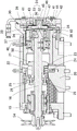
图1为实施方式中滚压总成的剖视图。FIG. 1 is a cross-sectional view of a rolling assembly in an embodiment.
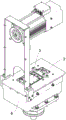
图2为实施方式中滚压总成的立体结构示意图。FIG. 2 is a schematic three-dimensional structure diagram of a rolling assembly in an embodiment.
图3为图2中隐藏部分结构的立体结构示意图。FIG. 3 is a schematic three-dimensional structure diagram of the structure of the hidden part in FIG. 2 .
图4为图1中A-A剖视图。FIG. 4 is a cross-sectional view A-A in FIG. 1 .
图5为对应图4的俯视示意图。FIG. 5 is a schematic top view corresponding to FIG. 4 .
图6为图1中局部的结构示意图。FIG. 6 is a schematic structural diagram of a part of FIG. 1 .
图7为图6的立体结构示意图。FIG. 7 is a schematic three-dimensional structure diagram of FIG. 6 .
图8为图7的俯视图。FIG. 8 is a plan view of FIG. 7 .
图9为图6的右视图。FIG. 9 is a right side view of FIG. 6 .
具体实施方式Detailed ways
参见附图,本实施方式中,滚压总成包括滚压机构,滚压机构包括有支撑壳15,支撑壳15上设有滚压轴16,滚压轴16转动及轴向移动设置,支撑壳15的前部还设有滚压套座装置30,滚压套座装置30包括有套座38与靠模44,靠模44连接在套座38的前端,滚压轴的前端设有楔块部37,滚压轴的前端连接有活块装置31,活块装置包括内活块32和外活块33;内活块32上具有楔孔36与楔块部配合,当滚压轴16进行轴向移动的时候,楔块部与楔孔配合能够使内活块偏心移动(偏向一侧移动),滚压轴进行转动的时候,通过楔块部与楔孔配合能够使内活块转动,因此当滚压轴即转动又轴向移动时,能够使内活块转动和偏心移动;内活块与外活块之间连接有第一轴承,内活块的偏心移动能够使外活块进行偏心移动,通过第一轴承使内活块在外活块内转动,外活块除了公转不用自转。外活块33位于套座38内;外活块33上还设有支轴45,支轴45随外活块进行移动(偏心移动和公转),支轴上设有第二轴承46,第二轴承46上设滚压轮47,由第二轴承46支撑滚压轮47在支轴上进行滚动;滚压轮47位于靠模44的内孔中,滚压轮47随外活块上的支轴进行偏心移动和公转,滚压轮与靠模的内孔配合进行滚压。滚压轴的转动和轴向移动并通过楔块部与楔孔的配合能够带动内活块转动以及偏心移动,从而使外活块在套座内能够偏心移动和公转,最终使滚压轮随外活块上的支轴进行偏心移动和公转,滚压轮与靠模的内孔配合进行滚压。该滚压总成采用新设计的活块装置,使与滚压轮安装的第二轴承可以采用较小的轴承,结构紧凑;活块装置中的第一轴承可以采用尺寸较大的轴承,第一轴承的使用寿命增长;第一轴承和第二轴承分别单向受力,不会双向正反受力,进一步提升使用寿命。且为端面密封结构的设置提供基础。Referring to the drawings, in this embodiment, the rolling assembly includes a rolling mechanism, the rolling mechanism includes a
套座38位于支撑壳15的前支撑孔内,前支撑孔与套座之间设有第三轴承50,由第三轴承50(如铜套)支撑套座38在前支撑孔中进行轴向滑动,套座连接有导杆51,支撑壳15上具有导套或导孔与导杆连接,通过导杆与导套或导孔配合进行导向,使套座能够稳定轴向滑动,避免转动。滚压套座装置的套座在支撑壳的前支撑孔内由第三轴承支撑可以进行轴向活动,从而为套座以及滚压套座装置的前后调整以及轴向缓冲提供技术支持。进一步优化,导杆51上配有张紧回位弹簧52,张紧回位弹簧位于套座与支撑壳之间,通过张紧回位弹簧能够使套座在支撑壳上进行轴向缓冲,通过导杆的端部还配有锁紧螺母53,由锁紧螺母限位在导套或导孔的一侧,通过锁紧螺母在导杆上的位置能够调整套座在支撑壳上的前后轴向位置,满足生产不同规格需求。The
外活块33上设有圆盘部34,套座38上设有环形槽39,圆盘部的圆周边缘由环形槽39围住,圆盘部的圆周边缘匹配在环形槽内,避免圆盘部34从环形槽39内脱离形成漏点,环形槽与圆盘部滑动配合,圆盘部的圆周边缘始终位于环形槽内并保持滑动配合,运行更稳定;套座38上设有进入通道40,进入通道40与环形槽39连通,环形槽内的前侧面具有密封圈安装槽,密封圈安装槽内配有密封圈41。由密封圈配合圆盘部进行密封阻隔,将润滑油从进入通道进入后避免润滑油和纸粉从圆盘部与环形槽之间通过,润滑油能够由进入通道进入到环形槽来润滑圆盘部在环形槽内移动,使外活块及圆盘部偏心移动更顺畅。润滑油则可以通过支撑壳15上的通道与进入通道衔接时通油。The outer
环形槽39内的前侧面或后侧面具有凹槽环,当润滑油进入后,圆盘部偏心转动能够使润滑油在里面翻滚,润滑效果更好,同时降低与圆盘部的滑动摩擦接触面。图中,凹槽环设置在环形槽的前侧面上,并在密封圈安装槽与凹槽环之间设置泄油通道,由泄油通道将密封圈安装槽与凹槽环进行连通,降低润滑油从密封圈安装槽处泄漏的风险。作为优选,密封圈可以采用星型密封圈,密封效果较佳。圆盘部上设有排出通道43,排出通道与环形槽连通,能够将进入到环形槽内的润滑油排出进行循环。The front side or rear side of the
套座38上设有台阶孔,台阶孔配有压板44,压板与台阶孔围成环形槽39,加工以及组装更方便,特别是环形槽内的前侧面上的凹槽环以及密封圈安装槽加工更简便,密封圈的装配更方便。The
滚压轴16上连接转动传动轮54,转动传动轮54位于支撑壳15外,当转动传动轮54进行转动时,能够带动滚压轴进行转动,转动传动轮可以由电机55传动,可以通过皮带驱动进行传动转动。本实施例中,支撑壳15设置在第一移动板1上,滚压轴16还与第二移动板2传动连接,第一移动板1连接在第一横向轨道上,第一横向轨道供第一移动板在第一横向轨道上进行横向往复移动,第二移动板2连接在第二横向轨道上,第二横向轨道供第二移动板在第二横向轨道上进行横向往复移动。底座6上设置旋转驱动立轴3,旋转驱动立轴3上传动连接有前进凸轮7和后退凸轮8,即旋转驱动立轴呈竖直状态,当旋转驱动立轴3转动时能够带动其上的前进凸轮7和后退凸轮8进行转动。比如,第一横向轨道和第二横向轨道均可以采用线轨(如V型),相应移动板上配置轮子在线轨上移动。The rolling
第一移动板1上设有前滚子9,前滚子9位于前进凸轮7的前侧,前进凸轮7与前滚子9顶传配合(即顶靠传动),第一移动板1还与第一弹簧装置10传动配合,第一弹簧装置10连接在第一移动板1与底座6之间。第二移动板2上设有后滚子13,后滚子13位于后退凸轮8的后侧,后退凸轮8与后滚子13顶传配合(即顶靠传动),第二移动板还与第二弹簧装置14传动配合,第二弹簧装置14连接在第二移动板与第一移动板之间。当前进凸轮顶传前滚子前进(图中1向右)时,前进凸轮的工作曲线逐渐凸出,前滚子与第一移动板同步前进,第一弹簧装置能够进行缓冲以及蓄力(比如第一弹簧装置采用压缩弹簧则进行压缩),第一移动板前进到位后,前进凸轮的工作曲线保持前滚子的位置;第二弹簧装置在第一移动板前进的时候变形带动(如第二弹簧装置采用压缩弹簧则进行压缩变形推动)第二移动板前进,后退凸轮的工作曲线内缩让位供后滚子以及第二移动板前进,直至第一移动板前进到位后,第二弹簧装置继续释放弹力作用给第二移动板前进直至到位(能够用于滚压工作保持延长和缓冲),然后后退凸轮的工作曲线凸出顶传后滚子后退(图中1向左),第二移动板与后滚子同步后退,接着前进凸轮的工作曲线让位供前滚子后退,第二移动板与后滚子同步后退则第二弹簧装置能够作用第一移动板后退,第一弹簧装置也将作用第一移动板后退,直至后退到位。The first moving plate 1 is provided with a
由一旋转驱动立轴上的前进凸轮和后退凸轮与第一弹簧装置、第二弹簧装置配合带动第一移动板以及第二移动板配合前进以及后退,传动结构更合理、更紧凑,运行稳定性较高,能够满足进一步提速需求;第一移动板用于安装滚压总成的支撑壳安装,支撑壳还将用于安装设置滚压套座装置,滚压轴在支撑壳上转动及轴向移动设置,第二移动板能够用于传动连接滚压轴,则能够带动滚压轴进行前进和后退,由第二弹簧装置配合能够使滚压工作保持延长和缓冲并且避免过载碰撞受损。The forward cam and the backward cam on the rotary drive vertical shaft cooperate with the first spring device and the second spring device to drive the first moving plate and the second moving plate to move forward and backward in coordination, the transmission structure is more reasonable and compact, and the running stability is relatively high. The first moving plate is used to install the support shell of the rolling assembly, and the support shell will also be used to install the rolling sleeve seat device, and the rolling shaft rotates and axially moves on the support shell. , the second moving plate can be used to drive and connect the rolling shaft, which can drive the rolling shaft to advance and retreat, and the cooperation of the second spring device can keep the rolling work extended and buffered and avoid overload and collision damage.
第一弹簧装置10包括有第一弹簧或第一气缸或第一液压缸,第二弹簧装置14包括有第二弹簧或第二气缸或第二液压缸。图中,第一弹簧装置采用第一弹簧(如压缩弹簧),第二弹簧装置采用第二弹簧(如压缩弹簧),可以设置相应的弹簧安装座供弹簧连接安装,还可以设置相应的弹簧导杆供弹簧套设使相应弹簧运行更稳定,弹簧导杆配相应的导孔。The
第一横向轨道设置在滚压总成的底座6上,第二横向轨道设置在第一连接板1上,第一连接板上设有缺口部,第二连接板2设置在缺口部;布局合理,结构更紧凑。滚压总成的传动机构能够配置在滚压总成的底座6上,随滚压总成进行整体更换,较为方便。The first transverse track is arranged on the
作为优先,本实施例中前进凸轮和后退凸轮为共轭凸轮上的两凸轮,形成共轭凸轮与前滚子、后滚子传动配合关系,更稳定,满足快速需求,使用寿命更长。As a priority, in this embodiment, the forward cam and the backward cam are two cams on the conjugate cam, forming a transmission cooperation relationship between the conjugate cam and the front roller and the rear roller, which is more stable, meets the fast demand, and has a longer service life.
旋转驱动立轴3与底座6之间设有第四轴承17,旋转驱动立轴3由第四轴承17支撑在底座上进行竖直立向的旋转。旋转驱动立轴的下部连接输入齿轮装置18,输入齿轮装置18位于底座的下端口的下方,通过输入齿轮装置将动力输入旋转驱动立轴上,带动旋转驱动立轴进行转动。前进凸轮、后退凸轮设置在第一移动板以及第二移动板的下方。A
滚压轴16上传动连接有传动套21,当滚压轴16被传动进行转动时,传动套21也将跟随进行同步转动。传动套21上具有周向设置的环形凹槽22,当传动套21转动时其环形凹槽也将进行相应的转动。第二移动板上设有传动座20,第二弹簧装置可以与传动座传动连接配合,传动座20上设有至少三个滚轮23,滚轮23配置在环形凹槽22内,三个滚轮相互间形成直角或锐角三角形。滚轮23可以在传动座20上进行滚动,传动座20上可以设置供滚轮23安装的滚轮轴24,滚轮23配置在环形凹槽22内,当传动座20被驱动进行前进和后退时(传动座由第二移动板带动前后移动),则可以通过滚轮与传动套的环形凹槽配合带动滚压轴前进和后退(轴向移动),同时又不影响滚压轴的转动;另外三个滚轮相互间形成直角或锐角三角形,使滚压轴被至少三个滚轮包围住,更加稳定,避免抖动。传动套与传动座之间的配合传动结构保滚压轴的轴向移动与转动相互之间能够稳定配合,且结构紧凑,避免抖动,满足高速运行需求。A
作为优选,滚轮23设置三个,三个滚轮分别位于环形凹槽的左侧、右侧和下侧,形成直角三角形分布,确保滚压轴在轴向移动与转动相互之间稳定配合的同时,方便装配。作为优选,环形凹槽与滚压轴同心设置,即轴心线处于同一直线上,稳定性进一步提升。图中滚压轴横向水平设置。本实施例中,传动座20上具有凹形口,三个滚轮分布在凹形口左、右和下。Preferably, three
传动套21套设在滚压轴上,滚压轴上并位于传动套的两侧分别设有锁紧螺母,滚压轴上设有外螺纹与锁紧螺母配合,调节两侧的锁紧螺母将调节并固定传动套在滚压轴上的位置,满足不同需求,即当滚压的尺寸、位置发生变化时可以进行调节。或者,更为优选的方案,更小紧凑,传动套21套设在滚压轴16上,滚压轴16上设有外螺纹,传动套21上设有内螺纹与外螺纹配合,传动套21具有径向开口锁槽25和轴向锁紧孔,径向开口锁槽与轴向锁紧孔连通,径向开口锁槽与内螺纹对应,轴向锁紧孔内配有锁紧紧固件26(如锁紧螺丝),通过传动套在滚压轴上转动调整位置,调整后再通过锁紧紧固件锁紧改变径向开口锁槽的大小,从而使内螺纹变形锁住咬合内螺纹上;径向开口锁槽与传动套的内孔连通,内螺纹位于传动套的内孔上,效果更好。传动套的外侧设置撬孔,方便使用工具扳动传动套在滚压轴上的螺纹配合转动。The
滚压轴与套座之间设有前旋转及轴向滑动支撑装置56,由前旋转及轴向滑动支撑装置对滚压轴进行转动和轴向滑动(移动)的支撑;滚压轴与支撑壳的后支撑孔之间设有后旋转及轴向滑动支撑装置57, 由后旋转及轴向滑动支撑装置对滚压轴进行转动和轴向滑动(移动)的支撑。本实施例中,前旋转及轴向滑动支撑装置包括有第五轴承和第一导向套(如铜套),滚压轴位于第一导向套内,第五轴承设置在第一导向套与套座之间,滚压轴在第一导向套内被支撑进行轴向移动,第一导向套由第五轴承支撑在套座上进行转动。第一导向套与滚压轴之间设有轴向滑键,滚压轴与第一导向套即能够相对轴向滑动,又能保持同步转动,更加稳定。后旋转及轴向滑动支撑装置包括有安装套、支撑滑套、第六轴承和第二导向套(如铜套),安装套连接在后支撑孔上,第二导向套位于安装套与支撑滑套之间,第六轴承设置在支撑滑套与滚压轴之间,由第六轴承支撑滚压轴在支撑滑套上转动,支撑滑套由第二导向套支撑进行轴向滑动,方便设置润滑油路,支撑滑套内可以设置隔套方便两边的第六轴承安装。安装套与支撑滑套之间设置密封圈,密封圈可以设置在安装套的装配凹槽内。There is a front rotation and axial sliding
Claims (10)
Priority Applications (2)
| Application Number | Priority Date | Filing Date | Title |
|---|---|---|---|
| CN201910928963.0A CN111761875B (en) | 2019-09-28 | 2019-09-28 | Rolling assembly |
| PCT/CN2020/115377 WO2021057559A1 (en) | 2019-09-28 | 2020-09-15 | Roll-pressing assembly |
Applications Claiming Priority (1)
| Application Number | Priority Date | Filing Date | Title |
|---|---|---|---|
| CN201910928963.0A CN111761875B (en) | 2019-09-28 | 2019-09-28 | Rolling assembly |
Publications (2)
| Publication Number | Publication Date |
|---|---|
| CN111761875A true CN111761875A (en) | 2020-10-13 |
| CN111761875B CN111761875B (en) | 2024-11-12 |
Family
ID=72718895
Family Applications (1)
| Application Number | Title | Priority Date | Filing Date |
|---|---|---|---|
| CN201910928963.0A Active CN111761875B (en) | 2019-09-28 | 2019-09-28 | Rolling assembly |
Country Status (2)
| Country | Link |
|---|---|
| CN (1) | CN111761875B (en) |
| WO (1) | WO2021057559A1 (en) |
Families Citing this family (1)
| Publication number | Priority date | Publication date | Assignee | Title |
|---|---|---|---|---|
| CN114132007B (en) * | 2021-12-29 | 2025-09-23 | 浙江上易机械股份有限公司 | A paper container bottom forming mechanism |
Citations (26)
| Publication number | Priority date | Publication date | Assignee | Title |
|---|---|---|---|---|
| CN2500470Y (en) * | 2001-09-30 | 2002-07-17 | 瑞安市胜利机械有限公司 | Bowl (cup) bottom rolling sealing mechanism for moulding machine of bowl (cup) double film paper |
| EP1407840A2 (en) * | 2002-10-11 | 2004-04-14 | Fette GmbH | Radial rolling head |
| KR20050017532A (en) * | 2003-08-14 | 2005-02-22 | (주)성우엔비테크 | Device for joining the bottom part of a paper cup in paper-cup forming machine |
| CN1861382A (en) * | 2006-06-14 | 2006-11-15 | 彭来静 | Device for knurling bottom of cubic paper cup of paper cup formation machine |
| CN101181826A (en) * | 2007-12-05 | 2008-05-21 | 戴道金 | Paper cup machine |
| CN201136309Y (en) * | 2007-12-05 | 2008-10-22 | 戴道金 | Cup bottom knurling mechanism for paper cup making machine |
| CN201161463Y (en) * | 2007-10-13 | 2008-12-10 | 黄友总 | Cup bottom rolling and sealing mechanism of high speed paper cup machine |
| CN201456464U (en) * | 2009-06-30 | 2010-05-12 | 浙江上易机械有限公司 | Eccentric rolling mechanism of paper container former |
| CN201566180U (en) * | 2009-12-07 | 2010-09-01 | 王建平 | Bottom rolling device of paper cup machine and paper bowl machine |
| US20120318807A1 (en) * | 2011-06-17 | 2012-12-20 | Berry Plastics Corporation | Process for forming an insulated container having artwork |
| CN203472207U (en) * | 2013-08-30 | 2014-03-12 | 瑞安市明国机械有限公司 | Bottom rolling device of paper cup forming machine |
| CN204123718U (en) * | 2014-09-05 | 2015-01-28 | 瑞安市瑞泽机械有限公司 | Paper cup making machine knurling mechanism |
| CN204136485U (en) * | 2014-09-27 | 2015-02-04 | 瑞安市胜利机械有限公司 | Sealing mechanism is rolled at the bottom of the cup of the radial direction pushing knurled wheel of paper cup making machine |
| CN104385684A (en) * | 2014-09-27 | 2015-03-04 | 瑞安市胜利机械有限公司 | Cup-bottom rolled-sealing mechanism of radial pushing-type paper cup |
| CN204820461U (en) * | 2015-07-29 | 2015-12-02 | 瑞安市明国机械有限公司 | Full -automatic paper cup forming machine's annular knurl device |
| JP2016147443A (en) * | 2015-02-13 | 2016-08-18 | 凸版印刷株式会社 | Knurled |
| CN205970148U (en) * | 2016-08-30 | 2017-02-22 | 浙江新德宝机械有限公司 | Paper cup or paper bowl annular knurl device |
| CN205970145U (en) * | 2016-08-30 | 2017-02-22 | 浙江新德宝机械有限公司 | Paper cup or paper bowl annular knurl device |
| CN206124320U (en) * | 2016-09-26 | 2017-04-26 | 瑞安市贝斯特机械有限公司 | Bowl cover machine and edge knurling machine constructs thereof |
| CN207128336U (en) * | 2017-08-31 | 2018-03-23 | 浙江新德宝机械有限公司 | Dixie cup or paper bowl bottom spinning machine |
| KR101848909B1 (en) * | 2016-11-29 | 2018-04-13 | 현진제업주식회사 | Apparatus for forming bottom part of paper-made cup |
| US20180135694A1 (en) * | 2016-11-17 | 2018-05-17 | Aktiebolaget Skf | Rolling-element bearing transmission |
| CN108839379A (en) * | 2018-05-23 | 2018-11-20 | 浙江庞度环保科技有限公司 | Paper cup making machine |
| CN208324359U (en) * | 2018-06-26 | 2019-01-04 | 浙江国豪机械有限公司 | A kind of bottom of a cup rolling sealing mechanism of paper cup making machine |
| CN209336174U (en) * | 2018-12-21 | 2019-09-03 | 浙江新立机械有限公司 | Paper bowl machine knurling mechanism |
| CN210759495U (en) * | 2019-09-28 | 2020-06-16 | 浙江新德宝机械有限公司 | Rolling assembly |
Family Cites Families (5)
| Publication number | Priority date | Publication date | Assignee | Title |
|---|---|---|---|---|
| EP2362123A1 (en) * | 2010-02-17 | 2011-08-31 | Aage V. Kjærs Maskinfabrik A/S | Underground shut-off valve with a hinged flap |
| CN210733414U (en) * | 2019-09-28 | 2020-06-12 | 浙江新德宝机械有限公司 | Transmission mechanism of rolling assembly |
| CN210679855U (en) * | 2019-09-28 | 2020-06-05 | 浙江新德宝机械有限公司 | Rolling mechanism with end face sealing structure |
| CN210679879U (en) * | 2019-09-28 | 2020-06-05 | 浙江新德宝机械有限公司 | Auxiliary transmission structure of rolling shaft of rolling assembly |
| CN110893697B (en) * | 2019-12-07 | 2026-03-31 | 浙江新德宝机械有限公司 | Horizontal high-speed paper cup or paper bowl forming machine |
-
2019
- 2019-09-28 CN CN201910928963.0A patent/CN111761875B/en active Active
-
2020
- 2020-09-15 WO PCT/CN2020/115377 patent/WO2021057559A1/en not_active Ceased
Patent Citations (27)
| Publication number | Priority date | Publication date | Assignee | Title |
|---|---|---|---|---|
| CN2500470Y (en) * | 2001-09-30 | 2002-07-17 | 瑞安市胜利机械有限公司 | Bowl (cup) bottom rolling sealing mechanism for moulding machine of bowl (cup) double film paper |
| EP1407840A2 (en) * | 2002-10-11 | 2004-04-14 | Fette GmbH | Radial rolling head |
| KR20050017532A (en) * | 2003-08-14 | 2005-02-22 | (주)성우엔비테크 | Device for joining the bottom part of a paper cup in paper-cup forming machine |
| CN1861382A (en) * | 2006-06-14 | 2006-11-15 | 彭来静 | Device for knurling bottom of cubic paper cup of paper cup formation machine |
| CN201161463Y (en) * | 2007-10-13 | 2008-12-10 | 黄友总 | Cup bottom rolling and sealing mechanism of high speed paper cup machine |
| CN101181826A (en) * | 2007-12-05 | 2008-05-21 | 戴道金 | Paper cup machine |
| CN201136309Y (en) * | 2007-12-05 | 2008-10-22 | 戴道金 | Cup bottom knurling mechanism for paper cup making machine |
| CN201456464U (en) * | 2009-06-30 | 2010-05-12 | 浙江上易机械有限公司 | Eccentric rolling mechanism of paper container former |
| CN201566180U (en) * | 2009-12-07 | 2010-09-01 | 王建平 | Bottom rolling device of paper cup machine and paper bowl machine |
| US20120318807A1 (en) * | 2011-06-17 | 2012-12-20 | Berry Plastics Corporation | Process for forming an insulated container having artwork |
| CN203472207U (en) * | 2013-08-30 | 2014-03-12 | 瑞安市明国机械有限公司 | Bottom rolling device of paper cup forming machine |
| CN204123718U (en) * | 2014-09-05 | 2015-01-28 | 瑞安市瑞泽机械有限公司 | Paper cup making machine knurling mechanism |
| CN204136485U (en) * | 2014-09-27 | 2015-02-04 | 瑞安市胜利机械有限公司 | Sealing mechanism is rolled at the bottom of the cup of the radial direction pushing knurled wheel of paper cup making machine |
| CN104385684A (en) * | 2014-09-27 | 2015-03-04 | 瑞安市胜利机械有限公司 | Cup-bottom rolled-sealing mechanism of radial pushing-type paper cup |
| JP2016147443A (en) * | 2015-02-13 | 2016-08-18 | 凸版印刷株式会社 | Knurled |
| CN204820461U (en) * | 2015-07-29 | 2015-12-02 | 瑞安市明国机械有限公司 | Full -automatic paper cup forming machine's annular knurl device |
| CN205970148U (en) * | 2016-08-30 | 2017-02-22 | 浙江新德宝机械有限公司 | Paper cup or paper bowl annular knurl device |
| CN205970145U (en) * | 2016-08-30 | 2017-02-22 | 浙江新德宝机械有限公司 | Paper cup or paper bowl annular knurl device |
| CN206124320U (en) * | 2016-09-26 | 2017-04-26 | 瑞安市贝斯特机械有限公司 | Bowl cover machine and edge knurling machine constructs thereof |
| CN108071785A (en) * | 2016-11-17 | 2018-05-25 | 斯凯孚公司 | Rolling bearing transmission mechanism |
| US20180135694A1 (en) * | 2016-11-17 | 2018-05-17 | Aktiebolaget Skf | Rolling-element bearing transmission |
| KR101848909B1 (en) * | 2016-11-29 | 2018-04-13 | 현진제업주식회사 | Apparatus for forming bottom part of paper-made cup |
| CN207128336U (en) * | 2017-08-31 | 2018-03-23 | 浙江新德宝机械有限公司 | Dixie cup or paper bowl bottom spinning machine |
| CN108839379A (en) * | 2018-05-23 | 2018-11-20 | 浙江庞度环保科技有限公司 | Paper cup making machine |
| CN208324359U (en) * | 2018-06-26 | 2019-01-04 | 浙江国豪机械有限公司 | A kind of bottom of a cup rolling sealing mechanism of paper cup making machine |
| CN209336174U (en) * | 2018-12-21 | 2019-09-03 | 浙江新立机械有限公司 | Paper bowl machine knurling mechanism |
| CN210759495U (en) * | 2019-09-28 | 2020-06-16 | 浙江新德宝机械有限公司 | Rolling assembly |
Also Published As
| Publication number | Publication date |
|---|---|
| WO2021057559A1 (en) | 2021-04-01 |
| CN111761875B (en) | 2024-11-12 |
Similar Documents
| Publication | Publication Date | Title |
|---|---|---|
| US11241857B2 (en) | Horizontal high-speed paper cup/paper bowl forming machine | |
| CN219747407U (en) | Deep groove ball bearing channel processing device | |
| WO2020199574A1 (en) | Toothed part rolling and spinning forming device and method | |
| CN210759495U (en) | Rolling assembly | |
| CN104690202B (en) | Main mould swinging type high-velocity cold headers | |
| CN116654710A (en) | Copper wire tractor with speed regulation function | |
| CN111761875A (en) | Rolling assembly | |
| CN110102633A (en) | Auxiliary die for side positioning | |
| CN101323177A (en) | Sliding block driving mechanism of multiple slide rod press machine | |
| CN105689401A (en) | Integrated cross wedge rolling mill driven by hydraulic motor | |
| CN119927112A (en) | A forging equipment for lightweight motor shaft of automobile | |
| CN211542546U (en) | New Horizontal High Speed Paper Cup or Paper Bowl Forming Machine | |
| CN101927596A (en) | Inking device of offset printing machine | |
| CN110900287B (en) | Bar and pipe slotting and blanking integrated linkage device based on same hydraulic compensation | |
| CN218656636U (en) | Fixed star thread rolling machine | |
| CN206242658U (en) | A kind of new type printing press roller transmission device | |
| CN102554696A (en) | Multi-station conversion indexing mechanism | |
| CN1018336B (en) | Dynamic stable two-roller horizontal hot-rolled pipe puncher | |
| CN116038502A (en) | A superfinishing method and superfinishing machine for the outer circular surface of an arc busbar bearing roller | |
| CN112157171B (en) | A horizontal swing shifter for the knife rest on a screen punching machine | |
| CN201625886U (en) | Machine head rotating and rolling wheel feeding mechanism of turning groove forming machine | |
| CN1075403C (en) | Rotary forming apparatus and method of rotary forming | |
| CN211866774U (en) | Liquid storage device groove cutting machine | |
| CN113492189A (en) | Mechanical press directly driven by cam | |
| CN223197980U (en) | A thread rolling machine spindle mounting structure |
Legal Events
| Date | Code | Title | Description |
|---|---|---|---|
| PB01 | Publication | ||
| PB01 | Publication | ||
| SE01 | Entry into force of request for substantive examination | ||
| SE01 | Entry into force of request for substantive examination | ||
| CB02 | Change of applicant information | ||
| CB02 | Change of applicant information |
Country or region after: China Address after: 325400 fengzhai nature village, Wandu village, Wanquan Town, Pingyang County, Wenzhou City, Zhejiang Province Applicant after: ZHEJIANG NEW DEBAO MACHINERY Co.,Ltd. Address before: No.23, Wansheng Road, furniture Park, light industry base, Wanquan Town, Pingyang County, Wenzhou City, Zhejiang Province Applicant before: ZHEJIANG NEW DEBAO MACHINERY Co.,Ltd. Country or region before: China |
|
| GR01 | Patent grant | ||
| GR01 | Patent grant |