CN111761925A - Ceramic product printing device and preparation process thereof - Google Patents
Ceramic product printing device and preparation process thereof Download PDFInfo
- Publication number
- CN111761925A CN111761925A CN202010425048.2A CN202010425048A CN111761925A CN 111761925 A CN111761925 A CN 111761925A CN 202010425048 A CN202010425048 A CN 202010425048A CN 111761925 A CN111761925 A CN 111761925A
- Authority
- CN
- China
- Prior art keywords
- printing
- ceramic product
- pair
- ceramic
- workbench
- Prior art date
- Legal status (The legal status is an assumption and is not a legal conclusion. Google has not performed a legal analysis and makes no representation as to the accuracy of the status listed.)
- Pending
Links
- 238000007639 printing Methods 0.000 title claims abstract description 67
- 239000000919 ceramic Substances 0.000 title claims abstract description 60
- 238000002360 preparation method Methods 0.000 title abstract description 7
- 230000007246 mechanism Effects 0.000 claims abstract description 20
- 230000000712 assembly Effects 0.000 claims abstract description 11
- 238000000429 assembly Methods 0.000 claims abstract description 11
- 238000007598 dipping method Methods 0.000 claims abstract description 6
- VYPSYNLAJGMNEJ-UHFFFAOYSA-N Silicium dioxide Chemical compound O=[Si]=O VYPSYNLAJGMNEJ-UHFFFAOYSA-N 0.000 claims description 22
- 239000000741 silica gel Substances 0.000 claims description 22
- 229910002027 silica gel Inorganic materials 0.000 claims description 22
- 238000004049 embossing Methods 0.000 claims description 10
- 238000004519 manufacturing process Methods 0.000 claims description 6
- 238000000034 method Methods 0.000 claims description 4
- 230000008569 process Effects 0.000 claims description 4
- 239000000463 material Substances 0.000 claims description 3
- 230000001502 supplementing effect Effects 0.000 claims description 3
- 239000003973 paint Substances 0.000 claims 2
- 238000010008 shearing Methods 0.000 claims 1
- 239000011248 coating agent Substances 0.000 abstract description 6
- 238000000576 coating method Methods 0.000 abstract description 6
- 230000005540 biological transmission Effects 0.000 description 6
- 238000009434 installation Methods 0.000 description 4
- 229920001296 polysiloxane Polymers 0.000 description 3
- 238000010586 diagram Methods 0.000 description 2
- 230000004048 modification Effects 0.000 description 2
- 238000012986 modification Methods 0.000 description 2
- 238000007790 scraping Methods 0.000 description 2
- 230000009471 action Effects 0.000 description 1
- 230000009286 beneficial effect Effects 0.000 description 1
- 238000001354 calcination Methods 0.000 description 1
- 239000004927 clay Substances 0.000 description 1
- 238000004040 coloring Methods 0.000 description 1
- 230000008878 coupling Effects 0.000 description 1
- 238000010168 coupling process Methods 0.000 description 1
- 238000005859 coupling reaction Methods 0.000 description 1
- 238000005034 decoration Methods 0.000 description 1
- 230000008034 disappearance Effects 0.000 description 1
- 230000000694 effects Effects 0.000 description 1
- 239000003302 ferromagnetic material Substances 0.000 description 1
- 230000006872 improvement Effects 0.000 description 1
- 229910052500 inorganic mineral Inorganic materials 0.000 description 1
- 230000005291 magnetic effect Effects 0.000 description 1
- 239000011707 mineral Substances 0.000 description 1
- 238000002156 mixing Methods 0.000 description 1
- 238000009740 moulding (composite fabrication) Methods 0.000 description 1
- 238000010298 pulverizing process Methods 0.000 description 1
- 239000002994 raw material Substances 0.000 description 1
- 238000001179 sorption measurement Methods 0.000 description 1
- XLYOFNOQVPJJNP-UHFFFAOYSA-N water Substances O XLYOFNOQVPJJNP-UHFFFAOYSA-N 0.000 description 1
Images


Classifications
-
- B—PERFORMING OPERATIONS; TRANSPORTING
- B41—PRINTING; LINING MACHINES; TYPEWRITERS; STAMPS
- B41F—PRINTING MACHINES OR PRESSES
- B41F17/00—Printing apparatus or machines of special types or for particular purposes, not otherwise provided for
- B41F17/001—Pad printing apparatus or machines
-
- B—PERFORMING OPERATIONS; TRANSPORTING
- B41—PRINTING; LINING MACHINES; TYPEWRITERS; STAMPS
- B41P—INDEXING SCHEME RELATING TO PRINTING, LINING MACHINES, TYPEWRITERS, AND TO STAMPS
- B41P2217/00—Printing machines of special types or for particular purposes
- B41P2217/10—Printing machines of special types or for particular purposes characterised by their constructional features
-
- B—PERFORMING OPERATIONS; TRANSPORTING
- B41—PRINTING; LINING MACHINES; TYPEWRITERS; STAMPS
- B41P—INDEXING SCHEME RELATING TO PRINTING, LINING MACHINES, TYPEWRITERS, AND TO STAMPS
- B41P2217/00—Printing machines of special types or for particular purposes
- B41P2217/50—Printing presses for particular purposes
Landscapes
- Devices For Post-Treatments, Processing, Supply, Discharge, And Other Processes (AREA)
Abstract
The invention provides a ceramic product printing device, which comprises: the horizontal driving assembly is arranged on the workbench; the base frame is driven by the transverse driving assembly to do transverse reciprocating motion, and a longitudinal driving assembly is arranged on the base frame; the coating mechanisms of the pair of printing assemblies are symmetrically arranged on the base frame, and comprise ink rollers and scrapers; the printing station is arranged between the pair of dipping tables. The ceramic product printing device and the preparation process thereof have high working efficiency.
Description
Technical Field
The invention relates to the technical field of ceramic product processing, in particular to a ceramic product printing device and a preparation process thereof.
Background
The ceramic is made up by using natural clay and various natural minerals as main raw materials and making them pass through such processes of pulverizing, mixing, forming and calcining. And ceramic printing is one kind of ceramic decoration.
Chinese patent CN207496222U discloses an impression type ceramic printing machine, which comprises a base with a gravure pattern plate, a blank support seat for supporting a ceramic product blank, and a color tank for containing water-based coloring materials, and is characterized in that: the frame reciprocating transverse motion under the drive of transverse motion mechanism, frame upper portion hoist and mount that relative transverse motion mechanism rigidity has the vertical motion of drive silica gel head vertical motion, the frame is provided with the collateral branch frame to frame both ends extension symmetry, the collateral branch frame install the ink roller in proper order, the side cylinder that a pair of symmetry set up, install in scraper, the brush of scraping the blade holder, the pivot and the collateral branch frame coupling of scraping the blade holder to under the lapse action of side cylinder, make and scrape the blade holder and rotate along the pivot and drive scraper, brush to intaglio pattern board pressfitting, its printing effect is stable, the phenomenon of pattern skew or disappearance does not appear in the stamp process. However, in the actual production process, the production efficiency is low, and the requirement of mass production on a large scale is difficult to meet.
In summary, how to improve the production efficiency of the ceramic product printing device is a problem that needs to be solved urgently by the technical personnel in the field.
Disclosure of Invention
The invention aims to provide a ceramic product printing device and a preparation process thereof, and solves the problem of low production efficiency of the conventional ceramic product printing device.
In order to solve the technical problems, the invention provides the following technical scheme: a ceramic ware printing apparatus, comprising:
the horizontal driving assembly is arranged on the workbench;
the base frame is driven by the transverse driving assembly to do transverse reciprocating motion, and a longitudinal driving assembly is arranged on the base frame;
the coating mechanisms of the pair of printing assemblies are symmetrically arranged on the base frame, and comprise ink rollers and scrapers;
the printing station is arranged between the pair of dipping tables.
Further, the ceramic product printing device comprises a conveying device, wherein the conveying device is used for intermittently conveying the ceramic products, so that the ceramic products can stay on the printing station one by one.
Further, the automatic lifting device comprises a base and a lifting mechanism, wherein the workbench is arranged on the base in a height-adjustable mode through the lifting mechanism.
Furthermore, the lifting mechanism comprises a scissor arm assembly and a second cylinder, the scissor arm assembly is arranged between the base and the workbench, and the second cylinder controls the lifting of the workbench through the scissor arm assembly.
Furthermore, the scissor arm assembly comprises a pair of outer fork arms, a pair of inner fork arms, a lower sliding rod, an upper sliding rod and a middle shaft, the upper end of each outer fork arm is pivoted on the upper pivoting seat at the bottom of the workbench, the lower end of each outer fork arm is connected with the lower sliding rod, the lower sliding rod is arranged on the lower sliding seat at the top of the base in a sliding manner, the upper end of each inner fork arm is connected with the upper sliding rod, the upper sliding rod is arranged on the upper sliding seat at the bottom of the workbench in a sliding manner, the lower end of each inner fork arm is pivoted on the lower pivoting seat at the top of the base, the middle parts of the outer fork arms and the middle parts of the inner fork arms are rotatably connected to the middle shaft, the second air cylinder is rotatably arranged on the lower sliding rod, and the piston rod of the second air cylinder is hinged to the middle shaft.
Furthermore, the longitudinal driving assembly further comprises a first air cylinder, the first air cylinder is arranged on the base frame, the connecting frame is connected and arranged on a piston rod of the first air cylinder, and an installation rod of the silica gel head is detachably connected to the connecting frame.
Furthermore, a connecting sleeve is fixedly connected to the connecting frame, a threaded hole is formed in the connecting sleeve, and the threaded column portion of the mounting rod is in threaded connection with the threaded hole.
Further, the top of the threaded column part is provided with a prism part, the upper end of the prism part penetrates through the through hole in the connecting frame and extends upwards, the connecting frame is provided with a limiting groove, the bottom of the limiting groove is embedded with a magnet, a locking part is fixed in the limiting groove through the magnet in an adsorption mode, and the locking part is provided with a locking hole matched with the prism part.
Further, the transverse driving assembly comprises a pair of supports and a linear module, the linear module is erected on the tops of the pair of supports, and the base frame is installed on a sliding block of the linear module.
The invention also aims to provide a preparation process adopting the ceramic product printing device, which comprises the following steps:
1) feeding: placing the ceramic product to be printed at a printing station;
2) printing: the two printing assemblies alternately perform printing treatment on the ceramic product positioned on the printing station;
3) blanking and supplementing: and when the ceramic product subjected to the printing treatment is moved away from the printing station, a ceramic product to be printed is placed at the printing station again.
According to the technical scheme, the invention has the following beneficial effects:
compared with the prior art, in the two printing assemblies of the ceramic product printing device, when the silica gel head of one printing assembly is pressed on the ceramic product, the silica gel head of the other printing assembly is pressed on the corresponding pattern plate coated with the ceramic glaze, so that the two printing assemblies can alternately print the ceramic product on the printing station, and the working efficiency is higher.
The invention is described in further detail below with reference to the figures and the detailed description.
Drawings
In order to more clearly illustrate the embodiments of the present invention or the technical solutions in the prior art, the drawings used in the description of the embodiments or the prior art will be briefly described below, it is obvious that the drawings in the following description are only embodiments of the present invention, and for those skilled in the art, other drawings can be obtained according to the provided drawings without creative efforts.
FIG. 1 is a schematic structural diagram of the present invention.
Fig. 2 is a partial structural schematic diagram of the present invention.
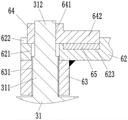
Fig. 3 is a schematic view of a further enlarged partial structure of the present invention.
Description of reference numerals: the automatic feeding device comprises a base 1, a lower sliding seat 11, a lower pivoting seat 12, a workbench 2, an upper sliding seat 21, an upper pivoting seat 22, a printing component 3, a silica gel head 31, a threaded column part 311, a prism part 312, a dipping platform 32, a coating mechanism 33, a transverse driving component 4, a support 41, a linear module 42, a base frame 5, a side support 51, a longitudinal driving component 6, a first cylinder 61, a connecting frame 62, a through hole 621, a limiting groove 622, an embedding groove 623, a connecting sleeve 63, a threaded hole 631, a locking piece 64, a locking hole 641, an extension arm 642, a magnet 65, a transmission device 7, a lifting mechanism 8, an outer fork arm 81, an inner fork arm 82, a second cylinder 83, a lower sliding rod 84, an upper sliding rod 85 and a middle shaft.
Detailed Description
The embodiments of the invention will be described in detail below with reference to the drawings, but the invention can be implemented in many different ways as defined and covered by the claims.
Referring to fig. 1 to 3, the invention will be further explained, as shown in fig. 1, the ceramic product embossing apparatus includes a base 1, a workbench 2, a pair of embossing assemblies 3, a base frame 5, a transmission device 7 and a lifting mechanism 8, a transverse driving assembly 4 is disposed on the workbench 2, the transverse driving assembly 4 includes a pair of brackets 41 and a linear module 42, the linear module 42 is mounted on the tops of the pair of brackets 41, the base frame 5 is mounted on a slide block of the linear module 42, so that the base frame 5 is driven by the transverse driving assembly 4 to make transverse reciprocating motion, a longitudinal driving assembly 6 is disposed on the base frame 5, dipping platforms 32 of the pair of embossing assemblies 3 are symmetrically disposed on the workbench 2, an embossing station is disposed between the pair of dipping platforms 32, a pattern plate is disposed on the top of the pattern platform 32, silica gel heads 31 of the pair of embossing assemblies 3 are symmetrically disposed on a connecting frame 62 of the longitudinal driving assembly 6, and the silica gel head 31 is driven by the longitudinal driving component 6 to do longitudinal reciprocating motion, the coating mechanisms 33 of the pair of printing components 3 are symmetrically arranged on side brackets 51 at two sides of the base frame 5, the coating mechanisms 33 comprise ink rollers, scrapers, a pair of symmetrically arranged side air cylinders and brushes, in the transverse moving process of the base frame 5, the coating mechanisms 33 coat ceramic glaze on corresponding pattern plates, the transmission device 7 adopts a belt conveying device, the transmission device 7 is used for intermittently conveying ceramic products to pass through printing stations, so that the ceramic products can be stopped at the printing stations one by one, the lifting mechanism 8 is arranged between the workbench 2 and the base 1, the height of the workbench 2 is adjustable, and the printing requirements of the ceramic products with different sizes can be met.
As shown in fig. 2, the lifting mechanism 8 includes a scissor arm assembly and a second cylinder 83, the scissor arm assembly is disposed between the base 1 and the worktable 2, the second cylinder 83 controls the lifting of the worktable 2 via the scissor arm assembly, and specifically, the scissor arm assembly includes a pair of outer fork arms 81, a pair of inner fork arms 82, a lower slide bar 84, an upper slide bar 85 and a central shaft 86, the upper ends of the pair of outer fork arms 81 are pivotally connected to the corresponding upper pivotally connected seats 22 at the bottom of the worktable 2, the lower ends of the pair of outer fork arms 81 are both connected to the lower slide bar 84, the lower slide bar 84 is slidably disposed on the lower slide seat 11 at the top of the base 1, the upper ends of the pair of inner fork arms 82 are both connected to the upper slide bar 85, the upper slide bar 85 is slidably disposed on the upper slide seat 21 at the bottom of the worktable 2, the lower ends of the pair of inner fork arms 82 are both pivotally connected to the corresponding lower pivotally connected seats 12 at the top of the base 1, the middle portions of the pair of outer fork arms 81, the second air cylinder 83 is rotatably arranged on the lower sliding rod 84, and a piston rod of the second air cylinder 83 is hinged with an extension rod fixedly connected to the central shaft 86.
As shown in fig. 1, the longitudinal driving assembly 6 further includes a first cylinder 61, the first cylinder 61 is fixedly disposed on the base frame 5, a connecting frame 62 is connected to a piston rod of the first cylinder 61, and a mounting rod of the silicone head 31 is detachably connected to the connecting frame 62, so as to facilitate replacement of the silicone head 31.
As shown in fig. 3, a connecting sleeve 63 is fixedly connected to the connecting frame 62, a threaded hole 631 is formed in the connecting sleeve 63, a threaded column 311 of the mounting rod is threadedly connected into the threaded hole 631, a prism 312 is arranged at the top of the threaded column 311, the upper end of the prism 312 can extend upwards through a through hole 621 formed in the connecting frame 62, a limiting groove 622 is formed in the connecting frame 62, a magnet 65 is embedded in an embedding groove 623 at the bottom of the limiting groove 622, the locking member 64 is made of a ferromagnetic material, an extension arm 642 of the locking member 64 can be attracted and fixed in the limiting groove 622 by the magnet 65, a locking hole 641 matched with the prism 312 is formed in the locking member 64, when the silicone head 31 is mounted, the mounting rod is first screwed so that the threaded column 311 of the mounting rod is threadedly connected into the threaded hole 631, then the locking member 64 is sleeved on the prism 312 of the mounting rod, and then the mounting rod is rotated so that, and then make the installation pole of silica gel head 31 unable to rotate to make silica gel head 31 be installed on link 62 reliably, and when dismantling silica gel head 31, overcome the magnetic force of magnet 65 earlier and dismantle locking piece 64, then rotate the installation pole and dismantle silica gel head 31 can, the installation of silica gel head 31, dismantle convenience very.
A preparation process adopting the ceramic product printing device comprises the following steps:
1) feeding: the conveying device 7 intermittently conveys the ceramic products to pass through the printing station, and when the conveying device 7 stops moving, the ceramic products to be printed just stay at the printing station;
2) printing: the ceramic product moving to the printing station is printed alternately by the two printing assemblies 3, specifically, in the interval when the transmission device 7 stops moving, when the silica gel head 31 on the left side moves to the position right above the printing station, the base frame 5 stops moving, then the first cylinder 61 drives the connecting frame 62 to move downwards to drive the silica gel head 31 on the left side to press on the ceramic product, meanwhile, the silica gel head 31 on the right side presses on the plate coated with the ceramic glaze on the right side, then the first cylinder 61 drives the connecting frame 62 to move upwards to reset, then, the transmission device 7 starts to drive the ceramic product which finishes printing processing to leave the printing station, meanwhile, the transverse driving assembly 4 drives the base frame 5 to move leftwards until the silica gel head 31 on the right side moves to the position right above the printing station, and meanwhile, the silica gel head 31 on the left side moves to the position right above the corresponding pattern plate, then, the first air cylinder 61 drives the connecting frame 62 to move downwards to drive the silica gel head 31 positioned on the right side to press on the ceramic product, and meanwhile, the silica gel head 31 positioned on the left side presses on the corresponding pattern plate coated with the ceramic glaze, so that the ceramic product moved to the printing station is printed alternately by the two printing assemblies 3;
3) blanking and supplementing: the conveying device 7 conveys the ceramic products to be printed to the printing station while conveying the ceramic products to be printed to leave the printing station.
Therefore, the ceramic product printing device has higher working efficiency.
The above is only a preferred embodiment of the present invention, and is not intended to limit the present invention, and various modifications and changes will occur to those skilled in the art. Any modification, equivalent replacement, or improvement made within the spirit and principle of the present invention should be included in the protection scope of the present invention.
Claims (10)
1. A ceramic ware embossing apparatus, comprising:
the device comprises a workbench (2), wherein a transverse driving assembly (4) is arranged on the workbench (2);
the base frame (5) is driven by the transverse driving component (4) to do transverse reciprocating motion, and a longitudinal driving component (6) is arranged on the base frame (5);
a pair of stamp subassemblies (3), dip in material platform (32) symmetry setting of a pair of stamp subassemblies (3) on workstation (2), dip in and be provided with the pattern board on material platform (32), the silica gel head (31) symmetry setting of a pair of stamp subassemblies (3) is in on link (62) of vertical drive assembly (6), just silica gel head (31) is in vertical reciprocating motion is done under the drive of vertical drive assembly (6), paint mechanism (33) symmetry setting of a pair of stamp subassemblies (3) is in on bed frame (5), paint mechanism (33) includes ink roller and scraper;
the printing station is arranged between the pair of dipping tables (32).
2. The ceramic product embossing apparatus as claimed in claim 1, further comprising a conveying device (7), said conveying device (7) being adapted to intermittently convey the ceramic products so that they can be individually rested on the embossing station.
3. Ceramic product printing apparatus according to claim 2, further comprising a base (1) and a lifting mechanism (8), wherein the working table (2) is height-adjustably arranged on the base (1) by means of the lifting mechanism (8).
4. The ceramic product printing device according to claim 3, wherein the lifting mechanism (8) comprises a scissor arm assembly and a second air cylinder (83), the scissor arm assembly is arranged between the base (1) and the workbench (2), and the second air cylinder (83) controls the lifting of the workbench (2) through the scissor arm assembly.
5. The ceramic product decorating device according to claim 4, wherein the shearing fork arm assembly comprises a pair of outer fork arms (81), a pair of inner fork arms (82), a lower slide bar (84), an upper slide bar (85) and a central shaft (86), the upper ends of the outer fork arms (81) are pivoted on the upper pivoting seat (22) at the bottom of the workbench (2), the lower ends of the outer fork arms (81) are connected with the lower slide bar (84), the lower slide bar (84) is slidably arranged on the lower slide seat (11) at the top of the base (1), the upper ends of the inner fork arms (82) are connected with the upper slide bar (85), the upper slide bar (85) is slidably arranged on the upper slide seat (21) at the bottom of the workbench (2), the lower ends of the inner fork arms (82) are pivoted on the lower pivoting seat (12) at the top of the base (1), the middle parts of the outer fork arms (81) and the middle parts of the inner fork arms (82) are rotatably connected with the central shaft (86) 86) And the second air cylinder (83) is rotatably arranged on the lower sliding rod (84), and a piston rod of the second air cylinder (83) is hinged with the middle shaft (86).
6. The ceramic product printing device according to claim 3, wherein the longitudinal driving assembly (6) further comprises a first air cylinder (61), the first air cylinder (61) is arranged on the base frame (5), the connecting frame (62) is connected and arranged on a piston rod of the first air cylinder (61), and a mounting rod of the silica gel head (31) is detachably connected on the connecting frame (62).
7. The ceramic product embossing device according to the claim 6, characterized in that the connecting frame (62) is fixedly connected with a connecting sleeve (63), the connecting sleeve (63) is provided with a threaded hole (631), and the threaded column part (311) of the mounting rod is screwed in the threaded hole (631).
8. The ceramic product printing device according to claim 7, wherein a prism part (312) is arranged at the top of the threaded pillar part (311), the upper end of the prism part (312) extends upwards through a through hole (621) in the connecting frame (62), a limiting groove (622) is arranged on the connecting frame (62), a magnet (65) is embedded in the bottom of the limiting groove (622), a locking part (64) is fixed in the limiting groove (622) in an absorbing manner through the magnet (65), and a locking hole (641) matched with the prism part (312) is arranged on the locking part (64).
9. Ceramic product printing apparatus according to claim 3, wherein the transverse drive assembly (4) comprises a pair of brackets (41) and a linear module (42), the linear module (42) being mounted on top of the pair of brackets (41), the base frame (5) being mounted on a slide of the linear module (42).
10. A process for manufacturing a ceramic product embossing apparatus as claimed in claim 1, comprising the steps of:
1) feeding: placing the ceramic product to be printed at a printing station;
2) printing: the two printing assemblies (3) alternately perform printing treatment on the ceramic products on the printing stations;
3) blanking and supplementing: and when the ceramic product subjected to the printing treatment is moved away from the printing station, a ceramic product to be printed is placed at the printing station again.
Priority Applications (1)
| Application Number | Priority Date | Filing Date | Title |
|---|---|---|---|
| CN202010425048.2A CN111761925A (en) | 2020-05-19 | 2020-05-19 | Ceramic product printing device and preparation process thereof |
Applications Claiming Priority (1)
| Application Number | Priority Date | Filing Date | Title |
|---|---|---|---|
| CN202010425048.2A CN111761925A (en) | 2020-05-19 | 2020-05-19 | Ceramic product printing device and preparation process thereof |
Publications (1)
| Publication Number | Publication Date |
|---|---|
| CN111761925A true CN111761925A (en) | 2020-10-13 |
Family
ID=72719587
Family Applications (1)
| Application Number | Title | Priority Date | Filing Date |
|---|---|---|---|
| CN202010425048.2A Pending CN111761925A (en) | 2020-05-19 | 2020-05-19 | Ceramic product printing device and preparation process thereof |
Country Status (1)
| Country | Link |
|---|---|
| CN (1) | CN111761925A (en) |
Cited By (3)
| Publication number | Priority date | Publication date | Assignee | Title |
|---|---|---|---|---|
| CN112590375A (en) * | 2020-12-24 | 2021-04-02 | 王丽 | Pottery bowl inner wall stamp equipment |
| CN113415070A (en) * | 2021-05-19 | 2021-09-21 | 杨松 | Production and processing is with pottery stamp line equipment |
| CN114161823A (en) * | 2021-12-06 | 2022-03-11 | 王渝皓 | Printing device for processing porcelain plate |
Citations (7)
| Publication number | Priority date | Publication date | Assignee | Title |
|---|---|---|---|---|
| US4593616A (en) * | 1983-10-04 | 1986-06-10 | Madag Maschinen-Und Apparatebau Dietikon Ag | Dabber printing machine with plural dabbers |
| CN204764099U (en) * | 2015-06-02 | 2015-11-18 | 宁波佳信旅游用品有限公司 | Liftable table |
| CN205573297U (en) * | 2016-04-22 | 2016-09-14 | 嘉善威尔尼绒业有限公司 | Stamp device with heat radiation structure |
| CN206678553U (en) * | 2017-03-30 | 2017-11-28 | 广东皓达科技有限公司 | A kind of double-colored ceramics of list print color machine |
| CN208101344U (en) * | 2018-04-16 | 2018-11-16 | 郭缅 | A kind of ceramics cup body pad printer |
| CN110509665A (en) * | 2019-10-09 | 2019-11-29 | 蓝思智能机器人(长沙)有限公司 | a printing machine |
| CN210148909U (en) * | 2019-02-02 | 2020-03-17 | 郭缅 | Multicolor ceramic pad printing machine |
-
2020
- 2020-05-19 CN CN202010425048.2A patent/CN111761925A/en active Pending
Patent Citations (7)
| Publication number | Priority date | Publication date | Assignee | Title |
|---|---|---|---|---|
| US4593616A (en) * | 1983-10-04 | 1986-06-10 | Madag Maschinen-Und Apparatebau Dietikon Ag | Dabber printing machine with plural dabbers |
| CN204764099U (en) * | 2015-06-02 | 2015-11-18 | 宁波佳信旅游用品有限公司 | Liftable table |
| CN205573297U (en) * | 2016-04-22 | 2016-09-14 | 嘉善威尔尼绒业有限公司 | Stamp device with heat radiation structure |
| CN206678553U (en) * | 2017-03-30 | 2017-11-28 | 广东皓达科技有限公司 | A kind of double-colored ceramics of list print color machine |
| CN208101344U (en) * | 2018-04-16 | 2018-11-16 | 郭缅 | A kind of ceramics cup body pad printer |
| CN210148909U (en) * | 2019-02-02 | 2020-03-17 | 郭缅 | Multicolor ceramic pad printing machine |
| CN110509665A (en) * | 2019-10-09 | 2019-11-29 | 蓝思智能机器人(长沙)有限公司 | a printing machine |
Cited By (4)
| Publication number | Priority date | Publication date | Assignee | Title |
|---|---|---|---|---|
| CN112590375A (en) * | 2020-12-24 | 2021-04-02 | 王丽 | Pottery bowl inner wall stamp equipment |
| CN112590375B (en) * | 2020-12-24 | 2023-01-17 | 杨成 | Pottery bowl inner wall stamp equipment |
| CN113415070A (en) * | 2021-05-19 | 2021-09-21 | 杨松 | Production and processing is with pottery stamp line equipment |
| CN114161823A (en) * | 2021-12-06 | 2022-03-11 | 王渝皓 | Printing device for processing porcelain plate |
Similar Documents
| Publication | Publication Date | Title |
|---|---|---|
| CN111761925A (en) | Ceramic product printing device and preparation process thereof | |
| CN208452552U (en) | A fully automatic 3D pad printing machine | |
| CN208118652U (en) | A kind of curved surface screen printing machine | |
| CN212446703U (en) | Multi-station pad printing machine | |
| CN109367207A (en) | A kind of efficient automatic screen printing machine | |
| CN105172338A (en) | Automatic detection and automatic unloading sorting wire mesh machine | |
| KR102099466B1 (en) | Automatic system for printing many colors on many sides of molded product by pad | |
| CN113211955A (en) | Device and method for printing color card | |
| CN212098037U (en) | Printing assembly line equipment | |
| CN211000400U (en) | Automatic screen printer | |
| CN212708586U (en) | a printer | |
| CN212147908U (en) | Rocker arm type screen printing machine | |
| CN204820619U (en) | Efficient digital product shell pattern silk screen printing equipment | |
| CN209794838U (en) | Efficient automatic screen printing machine | |
| CN204845104U (en) | A kind of automatic printing equipment | |
| CN114347639B (en) | Curved glass printing method | |
| CN210139690U (en) | Automatic location silk screen printing machine | |
| CN213056380U (en) | Automatic printing device for gift box | |
| CN207257063U (en) | Multi-functional shuttle type offset beam printing machine | |
| CN115195275B (en) | Six-color metal plate printer convenient for color difference adjustment | |
| CN111055587A (en) | Printing device | |
| CN216268114U (en) | Automatic silk screen printing machine | |
| CN114161823B (en) | Printing device for ceramic disc machining | |
| CN214419891U (en) | Special-shaped bottle screen printing device | |
| CN213472538U (en) | Tool of bottle body stamping machine |
Legal Events
| Date | Code | Title | Description |
|---|---|---|---|
| PB01 | Publication | ||
| PB01 | Publication | ||
| SE01 | Entry into force of request for substantive examination | ||
| SE01 | Entry into force of request for substantive examination | ||
| RJ01 | Rejection of invention patent application after publication |
Application publication date: 20201013 |
|
| RJ01 | Rejection of invention patent application after publication |