CN1118329C - Carrier parts for exhaust gas catalysts - Google Patents
Carrier parts for exhaust gas catalysts Download PDFInfo
- Publication number
- CN1118329C CN1118329C CN97190610A CN97190610A CN1118329C CN 1118329 C CN1118329 C CN 1118329C CN 97190610 A CN97190610 A CN 97190610A CN 97190610 A CN97190610 A CN 97190610A CN 1118329 C CN1118329 C CN 1118329C
- Authority
- CN
- China
- Prior art keywords
- sheet metal
- carrier body
- upstream
- ripple
- catchment
- Prior art date
- Legal status (The legal status is an assumption and is not a legal conclusion. Google has not performed a legal analysis and makes no representation as to the accuracy of the status listed.)
- Expired - Fee Related
Links
Images


Classifications
-
- B—PERFORMING OPERATIONS; TRANSPORTING
- B01—PHYSICAL OR CHEMICAL PROCESSES OR APPARATUS IN GENERAL
- B01J—CHEMICAL OR PHYSICAL PROCESSES, e.g. CATALYSIS OR COLLOID CHEMISTRY; THEIR RELEVANT APPARATUS
- B01J35/00—Catalysts, in general, characterised by their form or physical properties
- B01J35/50—Catalysts, in general, characterised by their form or physical properties characterised by their shape or configuration
- B01J35/56—Foraminous structures having flow-through passages or channels, e.g. grids or three-dimensional [3D] monoliths
-
- F—MECHANICAL ENGINEERING; LIGHTING; HEATING; WEAPONS; BLASTING
- F01—MACHINES OR ENGINES IN GENERAL; ENGINE PLANTS IN GENERAL; STEAM ENGINES
- F01N—GAS-FLOW SILENCERS OR EXHAUST APPARATUS FOR MACHINES OR ENGINES IN GENERAL; GAS-FLOW SILENCERS OR EXHAUST APPARATUS FOR INTERNAL-COMBUSTION ENGINES
- F01N3/00—Exhaust or silencing apparatus having means for purifying, rendering innocuous, or otherwise treating exhaust
- F01N3/08—Exhaust or silencing apparatus having means for purifying, rendering innocuous, or otherwise treating exhaust for rendering innocuous
- F01N3/10—Exhaust or silencing apparatus having means for purifying, rendering innocuous, or otherwise treating exhaust for rendering innocuous by thermal or catalytic conversion of noxious components of exhaust
- F01N3/24—Exhaust or silencing apparatus having means for purifying, rendering innocuous, or otherwise treating exhaust for rendering innocuous by thermal or catalytic conversion of noxious components of exhaust characterised by constructional aspects of converting apparatus
- F01N3/28—Construction of catalytic reactors
- F01N3/2803—Construction of catalytic reactors characterised by structure, by material or by manufacturing of catalyst support
- F01N3/2807—Metal other than sintered metal
- F01N3/281—Metallic honeycomb monoliths made of stacked or rolled sheets, foils or plates
-
- F—MECHANICAL ENGINEERING; LIGHTING; HEATING; WEAPONS; BLASTING
- F01—MACHINES OR ENGINES IN GENERAL; ENGINE PLANTS IN GENERAL; STEAM ENGINES
- F01N—GAS-FLOW SILENCERS OR EXHAUST APPARATUS FOR MACHINES OR ENGINES IN GENERAL; GAS-FLOW SILENCERS OR EXHAUST APPARATUS FOR INTERNAL-COMBUSTION ENGINES
- F01N3/00—Exhaust or silencing apparatus having means for purifying, rendering innocuous, or otherwise treating exhaust
- F01N3/08—Exhaust or silencing apparatus having means for purifying, rendering innocuous, or otherwise treating exhaust for rendering innocuous
- F01N3/10—Exhaust or silencing apparatus having means for purifying, rendering innocuous, or otherwise treating exhaust for rendering innocuous by thermal or catalytic conversion of noxious components of exhaust
- F01N3/24—Exhaust or silencing apparatus having means for purifying, rendering innocuous, or otherwise treating exhaust for rendering innocuous by thermal or catalytic conversion of noxious components of exhaust characterised by constructional aspects of converting apparatus
- F01N3/28—Construction of catalytic reactors
- F01N3/2803—Construction of catalytic reactors characterised by structure, by material or by manufacturing of catalyst support
- F01N3/2807—Metal other than sintered metal
- F01N3/281—Metallic honeycomb monoliths made of stacked or rolled sheets, foils or plates
- F01N3/2814—Metallic honeycomb monoliths made of stacked or rolled sheets, foils or plates all sheets, plates or foils being corrugated
-
- F—MECHANICAL ENGINEERING; LIGHTING; HEATING; WEAPONS; BLASTING
- F01—MACHINES OR ENGINES IN GENERAL; ENGINE PLANTS IN GENERAL; STEAM ENGINES
- F01N—GAS-FLOW SILENCERS OR EXHAUST APPARATUS FOR MACHINES OR ENGINES IN GENERAL; GAS-FLOW SILENCERS OR EXHAUST APPARATUS FOR INTERNAL-COMBUSTION ENGINES
- F01N2330/00—Structure of catalyst support or particle filter
- F01N2330/30—Honeycomb supports characterised by their structural details
- F01N2330/32—Honeycomb supports characterised by their structural details characterised by the shape, form or number of corrugations of plates, sheets or foils
- F01N2330/321—Honeycomb supports characterised by their structural details characterised by the shape, form or number of corrugations of plates, sheets or foils with two or more different kinds of corrugations in the same substrate
-
- Y—GENERAL TAGGING OF NEW TECHNOLOGICAL DEVELOPMENTS; GENERAL TAGGING OF CROSS-SECTIONAL TECHNOLOGIES SPANNING OVER SEVERAL SECTIONS OF THE IPC; TECHNICAL SUBJECTS COVERED BY FORMER USPC CROSS-REFERENCE ART COLLECTIONS [XRACs] AND DIGESTS
- Y10—TECHNICAL SUBJECTS COVERED BY FORMER USPC
- Y10T—TECHNICAL SUBJECTS COVERED BY FORMER US CLASSIFICATION
- Y10T428/00—Stock material or miscellaneous articles
- Y10T428/12—All metal or with adjacent metals
- Y10T428/1234—Honeycomb, or with grain orientation or elongated elements in defined angular relationship in respective components [e.g., parallel, inter- secting, etc.]
-
- Y—GENERAL TAGGING OF NEW TECHNOLOGICAL DEVELOPMENTS; GENERAL TAGGING OF CROSS-SECTIONAL TECHNOLOGIES SPANNING OVER SEVERAL SECTIONS OF THE IPC; TECHNICAL SUBJECTS COVERED BY FORMER USPC CROSS-REFERENCE ART COLLECTIONS [XRACs] AND DIGESTS
- Y10—TECHNICAL SUBJECTS COVERED BY FORMER USPC
- Y10T—TECHNICAL SUBJECTS COVERED BY FORMER US CLASSIFICATION
- Y10T428/00—Stock material or miscellaneous articles
- Y10T428/24—Structurally defined web or sheet [e.g., overall dimension, etc.]
- Y10T428/24149—Honeycomb-like
Landscapes
- Chemical & Material Sciences (AREA)
- Engineering & Computer Science (AREA)
- Chemical Kinetics & Catalysis (AREA)
- Mechanical Engineering (AREA)
- Toxicology (AREA)
- Combustion & Propulsion (AREA)
- Health & Medical Sciences (AREA)
- General Engineering & Computer Science (AREA)
- Materials Engineering (AREA)
- Organic Chemistry (AREA)
- Catalysts (AREA)
- Exhaust Gas After Treatment (AREA)
- Exhaust Gas Treatment By Means Of Catalyst (AREA)
Abstract
Description
技术领域technical field
本发明涉及一种废气催化剂用的载体部件,更具体地涉及一种金属载体部件,它包括卷绕的、叠合的或以其它方式分层的多层高温耐腐蚀金属薄片,它们形成多个通道或通路,能使废气通过这些通路流动。The present invention relates to a carrier part for exhaust gas catalyst, more particularly to a metal carrier part, which comprises coiled, stacked or otherwise layered multi-layer high-temperature corrosion-resistant metal sheets, which form multiple Channels or passages through which exhaust gases flow.
背景技术Background technique
此种金属载体部件用于例如汽车的废气系统中。这些载体部件暴露于严重的交变热应力中,后者限制载体部件的使用寿命。Such metal carrier parts are used, for example, in the exhaust system of motor vehicles. These carrier parts are exposed to severe alternating thermal stresses, which limit the service life of the carrier parts.
已经提出了增大此种载体部件的弹性和控制压力与拉伸力的各种方法。日本公布的未审批申请JP-A62-83044(对应于德国公布的未审批申请DE-A3534904)公开了一种催化剂载体部件,该部件用两种不相同的金属薄片(薄板)的交替层制成,包括一种带双波纹的第一金属薄片和一种不带波纹的第二金属薄片。在这种类型的载体部件中,两种金属薄片之间的接触点的数目减少,由此提供需要的弹性。日本公布的未审批申请JP-A6-269683公开一种催化剂载体部件,其中形成交替层的两种不相同的金属薄片分别是一种带简单波纹的第一金属薄片和一种不带波纹的第二金属薄片。根据该已知的载体部件,第一和第二金属薄片中至少一种具有切口或开孔。或者是,第一和第二金属薄片中至少一种分为多个间隔排列的区段。在这种载体部件中,区段之间的切口或开孔或间隔可以控制压力和拉伸力。Various methods of increasing the elasticity of such carrier members and of controlling compressive and tensile forces have been proposed. Japanese published unexamined application JP-A62-83044 (corresponding to German published unexamined application DE-A3534904) discloses a catalyst support part made of alternating layers of two different metal sheets (sheets) , comprising a first metal sheet with double corrugations and a second metal sheet without corrugations. In this type of carrier part, the number of contact points between the two metal sheets is reduced, thereby providing the required elasticity. Japanese published unexamined application JP-A6-269683 discloses a catalyst support member in which two different metal sheets forming alternating layers are a first metal sheet with simple corrugations and a second non-corrugated sheet. Two metal sheets. According to this known carrier part, at least one of the first and second metal foils has cutouts or openings. Alternatively, at least one of the first and second metal sheets is divided into a plurality of spaced apart segments. In such carrier components, cuts or openings or spaces between segments can control compressive and tensile forces.
已知有用两种不同波纹的金属薄片的交替层卷绕成的载体部件。在1989年7月4日颁布给Cyron的US-A4,845,073中描述了一个例子。在这种已知的载体部件中,金属薄片有内外表面,接触点设置在第一金属薄片的内表面和第二金属薄片的外表面上。在卷绕期间,向内取向的波谷与第二金属薄片的向内取向的波谷同步。Carrier parts are known which are wound from alternating layers of two differently corrugated metal sheets. An example is described in US-A 4,845,073, issued July 4, 1989 to Cyron. In this known carrier part, the metal foils have inner and outer surfaces, the contact points being arranged on the inner surface of the first metal foil and on the outer surface of the second metal foil. During winding, the inwardly directed troughs are synchronized with the inwardly oriented troughs of the second metal sheet.
本发明的目的是提供一种废气催化剂用的载体部件,该部件具有足够高的结构刚性,待加热的质量减小,而暴露给废气的有效表面积增大。It is an object of the present invention to provide a carrier part for an exhaust gas catalyst which has a sufficiently high structural rigidity, reduces the mass to be heated and increases the effective surface area exposed to the exhaust gas.
发明的公开内容Disclosure of Invention
根据本发明的一个方面,本发明提供一种废气催化剂用的载体部件,它包括:According to one aspect of the present invention, the present invention provides a carrier part for an exhaust gas catalyst, which includes:
第一和第二金属薄片的多层结构,形成使气体流动通过的通路相对于气体流动的方向,所述多层结构有一个上游区和一个下游区,这两个区互相隔开;a multilayer structure of first and second metal sheets forming a passage for gas flow therethrough with respect to the direction of gas flow, said multilayer structure having an upstream zone and a downstream zone, the two zones being spaced apart from each other;
所述多层结构有一个设置在所述上游区和下游区之间的中间区;said multilayer structure has an intermediate zone disposed between said upstream zone and downstream zone;
所述第一金属薄片具有这样的波纹,使得所述第一波纹在所述上游区和下游区的每个区内与所述第二金属薄片接触;said first metal sheet has corrugations such that said first corrugations are in contact with said second metal sheet in each of said upstream and downstream regions;
所述第一金属薄片在所述中间区内不与所述第二金属薄片接触。The first metal foil is not in contact with the second metal foil in the intermediate region.
根据本发明的一个特定方面,第二金属薄片的波纹不同于第一波纹状金属薄片,而且其中不同波纹的第一和第二金属薄片具有周期性,这种周期性使它们能够在每个上游区和下游区内互相同步。According to a particular aspect of the invention, the corrugations of the second foil are different from those of the first corrugated foil, and wherein the first and second foils of different corrugations have a periodicity which enables them to Zone and downstream zone are synchronized with each other.
根据本发明的另一个特定方面,不同波纹的第一和第二金属薄片中只有一种延伸在所述中间区内。According to another particular aspect of the invention, only one of the differently corrugated first and second metal sheets extends within said intermediate zone.
根据本发明的再一个特定方面,第一金属薄片具有第一波纹,该第一波纹具有第一周期和第一波幅,而第二金属薄片具有第二波纹,该第二波纹具有第二周期和第二波幅。第一周期基本上等于第二周期的第二波幅小于第一波幅。第一和第二金属薄片中只有一种延伸在中间区内。According to yet another particular aspect of the invention, the first metal sheet has first corrugations with a first period and a first amplitude, and the second metal sheet has second corrugations with a second period and a first amplitude. second wave. The first period is substantially equal to the second period and the second amplitude is smaller than the first amplitude. Only one of the first and second foils extends within the intermediate region.
根据本发明的又一个特定方面,在上游区和下游区的每一个中,第一金属薄片具有一个具有第一周期和第一波幅的第一波纹,而在中间区内,第一金属薄片具有一个具有第二周期和第二波幅的第二波纹,该第二波幅小于第一波幅。According to yet another particular aspect of the invention, in each of the upstream zone and the downstream zone the first metal sheet has a first corrugation with a first period and a first amplitude, and in the intermediate zone the first metal sheet has A second corrugation having a second period and a second amplitude that is less than the first amplitude.
附图简述Brief description of the drawings
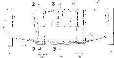
图1是一种催化转换器的部分纵向剖开的纵向视图;Fig. 1 is a longitudinal view of a partial longitudinal section of a catalytic converter;
图2是通过图1中线2-2截取的截面图,表示本发明的载体部件的第一实施例的一部分;Fig. 2 is a sectional view taken through line 2-2 in Fig. 1, showing a part of the first embodiment of the carrier member of the present invention;
图3是通过图1中线3-3截取的截面图,表示本发明的第一实施例的另一部分;Fig. 3 is a sectional view taken through line 3-3 in Fig. 1, showing another part of the first embodiment of the present invention;
图4是图2的局部放大图;Figure 4 is a partial enlarged view of Figure 2;
图5是图3的局部放大图;Fig. 5 is a partial enlarged view of Fig. 3;
图6是本发明的载体部件的第二实施例的局部图;Figure 6 is a partial view of a second embodiment of the carrier part of the present invention;
图7是通过图6的线7-7截取的截面图;Figure 7 is a cross-sectional view taken through line 7-7 of Figure 6;
图8是通过图6的线8-8截取的截面图;Figure 8 is a cross-sectional view taken through line 8-8 of Figure 6;
图9是通过图6的线9-9截取的截面图;Figure 9 is a cross-sectional view taken through line 9-9 of Figure 6;
图10是通过图6的线10-10截取的截面图;Figure 10 is a cross-sectional view taken through line 10-10 of Figure 6;
图11是通过图6的线11-11截取的截面图;Figure 11 is a cross-sectional view taken through line 11-11 of Figure 6;
图12是载体部件一部分的局部透视图;Figure 12 is a partial perspective view of a portion of a carrier member;
图13是载体部件另一部分的局部透视图;Figure 13 is a partial perspective view of another part of the carrier member;
图14类似于图6,示出本发明的载体部件的第三实施例;Fig. 14 is similar to Fig. 6, shows the third embodiment of the carrier part of the present invention;
图15是通过图14的线15-15截取的截面图;Figure 15 is a cross-sectional view taken through line 15-15 of Figure 14;
图16是通过图14的线16-16截取的截面图;Figure 16 is a cross-sectional view taken through line 16-16 of Figure 14;
图17是通过图14的线17-17截取的截面图;Figure 17 is a cross-sectional view taken through line 17-17 of Figure 14;
图18是通过图14的线18-18截取的截面图;Figure 18 is a cross-sectional view taken through line 18-18 of Figure 14;
图19是通过图14的线19-19截取的截面图;Figure 19 is a cross-sectional view taken through line 19-19 of Figure 14;
实施本发明的最佳方式Best Mode for Carrying Out the Invention
参照附图,特别参照图1,从内燃机出来的废气沿箭头10的方向供向废气转换器(净化器)12。废气转换器12有一个贝壳状外壳14。外壳14沿其纵向的一端为入口16,而其另一端为出口18。废气催化剂用的载体部件20有一个支承件22,它被安装在外壳14中。载体部件20可以分为和包括三个区,即上游区30、下游区32及在上下游区30和32之间的中游区34。Referring to the drawings, especially to FIG. 1 , the exhaust gas from the internal combustion engine is supplied to the exhaust gas converter (purifier) 12 in the direction of
图2表示上游区30中的排气通路36,而图4为其局部放大图。下游区32的构造与上游区30相同。图3表示中游区34中的排气通路38,而图5为其局部放大图。在上下游区的每个区中,载体部件20包括两种不同波纹的金属薄片即第一金属薄片40和第二金属薄片42的交替叠合层。在中间区34中,载体部件20包括两种不同波形金属薄片40和42之一的间隔层。FIG. 2 shows the
两种波纹的金属薄片40和42具有周期性,使它们能够当其叠合时彼此同步。结果是接触点的分布非常均匀,接触点具有彼此适合的形状和在两种薄板40和42之间的相同弯曲方向。The two
参看图4,第一金属薄片40具有上下表面44和46,而第二金属薄片42具有上下表面48和50。接触点可以分为第一组和第二组。第一组接触点位于第一金属薄片40的下表面46上和第二金属薄片42的上表面48上。换句话说,在一个接一个叠合金属薄片40和42期间,第一金属薄片40的波形的向下取向的波谷与第二金属薄片42的波形的向下取向的波谷同步。第二组接触点位于第一金属薄片40的上表面44上和第二金属薄片42的下表面50上。换句话说,在一个接一个叠合金属薄片40和42期间,第一金属薄片40的波形的向上取向的波峰与第二金属薄片42的波形的向上取向的波峰同步。Referring to FIG. 4 , the
在该例子中,第一金属薄片40沿载体部件20的纵向延伸通过上游区30、中游区34和下游区32的整个长度。第二金属薄片42仅仅延伸通过上游区30的整个长度和下游区32的整个长度32。换句话说,如图3和5所示,第二金属薄片42并不延伸通过中间区34。In this example, the
第一金属薄片40的波纹具有周期P1和波幅A1,而第二金属薄片42的波纹具有周期P2和波幅A2。P2与P1基本相同,而A2比A1小得多,使得接触点处第一金属薄片40的曲率稍许大于接触点处第二金属薄片42的留率。The corrugations of the
最好是,P1=P2,A1=nP1而A1=mA2,其中n的范围为0.2至0.3,m的范围为2.4至6。Preferably, P1=P2, A1=nP1 and A1=mA2, where n ranges from 0.2 to 0.3 and m ranges from 2.4 to 6.
在该例子中,波纹基本上为正弦曲线。波形为正弦波形。第一金属薄片40的波高2A1(波幅A1的两倍)为1.2mm,而波长P1的范围为2.0mm至3.0mm。第二金属薄片42的波高2A2(波幅A2的两倍)的范围为0.2至0.5mm,而波长P2基本上等于P1。In this example, the corrugations are substantially sinusoidal. The waveform is a sinusoidal waveform. The wave height 2A1 (twice the amplitude A1 ) of the
由于P1基本上等于P2,第一金属薄片40的叠层的波峰和波谷沿纵向通过中间区34的整个长度对准。在中间区34中,通路38的截面不会产生特别窄或特别宽的情况。这在随后用催化剂材料涂敷载体部件20时是有利的,因为不会产生会堵塞的小间隙。Since P1 is substantially equal to P2, the crests and troughs of the stack of
因此,在中间区34中,第一金属薄片40具有足够宽的能够接触废气的有效表面面积,即催化剂涂层的表面积。这可以尽可能减少催化剂涂层的浪费。Therefore, in the
此外,可以保证废气与催化剂涂层充分接触,从而提高催化剂的转换效率。In addition, it can ensure that the exhaust gas is fully in contact with the catalyst coating, thereby improving the conversion efficiency of the catalyst.
在冷起动期间,废气转换器12的催化剂低于其起动温度,因而必须通过发动机的废气提高到它的工作温度。待加热的催化剂的质量越小,它就越快地达到其起动温度。在载体部件20的中间区34内没有使用第二金属薄片42,使待加热的质量减小。其结果是减少了将催化剂加热到其起动温度所需的时间。During a cold start, the catalyst of the
在载体部件20的中间区34内,因为波峰和波谷沿载体部件20的纵向保持对准,所以第一金属薄片40的叠合层可以密集而不会产生任何可能变成堵塞的局部狭窄间隙。这对于增大向废气暴露的催化剂涂层的有效表面积是有利的。In the
参照图4,第一金属薄片40的相邻多层之间的距离H可以由于使用波幅A2增大的第二金属薄片42的多层而变窄。Referring to FIG. 4 , the distance H between adjacent multiple layers of the
在前面叙述的实施例中,在中间区34中已经除去第二中间薄片42。另一种办法是,可以在载体部件20的中间区34中除去第一金属薄片40。In the previously described embodiments, the second
按照第一实施例,载体部件20由两种不相似的或不同波形的金属薄片40和42的叠层构成。但是,本发明可以做成一种包括不同波形金属薄片40和42的卷绕层的载体部件。According to a first embodiment, the
在载体部件20的第一实施例中,由于在中间区34中除去了第二金属薄片42,因此在中间区34中不存在第一和第二金属薄片40和42之间的接触点。In the first embodiment of the
在下面叙述的第二实施例中,一种双波纹金属薄片用作第一金属薄片。双波纹金属薄片除了第一波纹外还包括一种第二波纹,其波幅小于第一波纹的波幅。在载体部件的每个上游区和下游区内,第一波纹与第二金属薄片的多层接触。在中间区内,第二波纹与第二金属薄片成间隔关系。换句话说,在中间区内不存在接触点。In the second embodiment described below, a double corrugated metal foil is used as the first metal foil. The double corrugated metal sheet includes, in addition to the first corrugations, a second corrugation whose amplitude is smaller than that of the first corrugations. In each upstream and downstream region of the carrier part, the first corrugations are in contact with multiple layers of the second foil. In the intermediate region, the second corrugation is in spaced relation to the second metal sheet. In other words, there are no contact points in the intermediate zone.
参照图6至13,其中描述载体部件60的第二实施例。Referring to Figures 6 to 13, a second embodiment of a
图6示出载体部件60的部分平面图,其中箭头10表示从内燃机出来供给到载体部件60的废气的方向。载体部件60可以分成和包括五个区,即上游区62、第一过渡区64、中间区66、第二过渡区68和下游区70。图7表示上游区62中的废气通路72。图8表示第一过渡区64中的废气通路74。图9表示中间区66中的废气通路76。图10表示第二过渡区68中的废气通路78。FIG. 6 shows a partial plan view of the
图11表示下游区70中的废气通路80。在这些区62、64、66、68和70的每一个中,载体部件60包括第一金属薄片82和第二金属薄片84的叠合交替层。在该例子中,第一金属薄片82具有双波纹,而第二金属薄片84是一个光滑的平面薄片。或者是,第二金属薄片84可以具有正弦波波形。与第一实施例不同,第二金属薄片84延伸通过第一过渡区64、中间区66和第二过渡区68的整个长度。FIG. 11 shows the
参看图7至图11,第一金属薄片82具有上下表面86和88,而第二金属薄片84具有上下表面90和92。第一和第二金属薄片82和84相互叠合。结果是大量接触点均匀分布在上下游区域62和72的每个区内(见图7和11)。在第一和第二过渡区64和70的每个区内出现少量接触点的均匀分布(见图8和10)。在中间区内(见图9),没有接触点。接触点可以分为第一组和第二组。第一组接触点设置在第一金属薄片82的下表面88上和第二金属薄片84的上表面90上。换句话说,在金属薄片82和84互相叠合期间,第一金属薄片82的双波纹的第一波纹94的向下取向的波谷与第二金属薄片84的上表面90接触。第二组接触点设置在第一金属薄片82的上表面86上和第二金属薄片84的下表面92上。换句话说,在金属薄片82和84叠合期间第一金属薄片82的第一波纹94的向上取向的波峰与第二金属薄片84的下表面92接触。Referring to FIGS. 7-11 , the
第一金属薄片82除了第一波纹94外还有一个第二波纹96。第一波纹94具有周期P3和波幅A3。第二波纹96具有周期P4和波幅A4。A4小于A3,而P4由下式表示:In addition to the
P4=P3×(1/N)式中:N≥2(N是整数)。P4=P3*(1/N) In the formula: N≥2 (N is an integer).
在该例子中,N为2,因此P4=P3×(1/2)成立。因为,在该例子中,波纹94和96基本上是正弦波而波形为正弦波形,所以第二波纹96的两个小波已取代了第一波纹94的一个大波。In this example, N is 2, so P4=P3×(1/2) holds. Since, in this example, corrugations 94 and 96 are substantially sinusoidal and the waveform is sinusoidal, two small waves of
回到图6,第一波纹94延伸通过用斜线(阴影线)表示的每个部分,而第二波纹96延伸通过每个空白部分。在图8、9和10中,虚线表示第一波纹94,它延伸通过上游区62。Returning to FIG. 6 , the
在图8所示的第一过渡区64中,如上所述,第二波纹96的两个小波已经取代了第一波纹94的每隔一个的大波。在图9所示的中间区66中,第二波纹96的两个小波已经取代了第一波纹94的另一个大波。在图10所示的第二过渡区68中,已经被第一过渡区64中的第二波纹96的两个小波取代的第一波纹94的每隔一个的大波如图12中所示地恢复原状。在图11所示的下游区70中,第一波纹94的所有大波都恢复原状。In the
沿上游区62和第一过渡区64之间的边界,从点C到一个点切割第一波纹94的每隔一个的大波,允许如图12中所示地形成第二波纹96的两个小波。沿第一过渡区64和中间区66之间的边界,从点d到点e切割第一波纹94的每一个剩余的大波,允许如图13中所示地形成第二波纹96的两个小波。Cutting every other large wave of the
以相似的方式,形成第二过渡区70中第二波纹96的小波。\;在载体部件60中,第二波纹96的小波已经取代了第一过渡区64、中间区66和第二过渡区68中第一波纹94的大多数大波。结果是大量减少了第一和第二金属薄片82和84之间的接触点数目。这对随后用催化剂材料涂敷载体部件60是有利的。In a similar manner, the wavelets of the
在上游区62和下游区70中,双波纹的第一金属薄片82固定在相邻的两层第二金属薄片84上。这对于金属薄片82保持其原先设计的形状是有效的。这提高了载体部件60的结构强度,使得可以延长使用寿命。In the
如上所述,在第二过渡区68之间的边界处第一波纹94的每隔一个的大波转换为第二波纹96的两个小波。结果是提高了第一波纹94和第二波纹96之间的整体性。As noted above, every other large wave of the
关系P4=P3×(1/N)成立,式中:N为整数并且不小于2。这在第一和第二过渡区64和68的每一个中形成第二波纹96的小波方面是有利的。这是因为第一波纹94的大波和第二波纹96的小波是光滑而连续地桥接的。结果,不仅提高了结构强度,而且还提高了生产率。The relationship P4=P3×(1/N) holds true, where: N is an integer and not less than 2. This is advantageous in forming wavelets of the
在载体部件60的第二实施例中,中间区66设置在上游区62和下游区70之间,在中间区只有第二波纹96的小波存在于第二金属薄片84的相邻两层之间。换句话说,大波支配区62、小波支配区66和大波支配区70是沿通过载体部件60的废气方向排列的。这种排列可以沿废气方向按周期重复。这种周期性排列在使通过载体部件的废气扩散得以增强方面是有利的。这导致提高催化剂的转换效率。这种排列沿废气方向并因而在载体部件的长度和宽度上增加接触点的分布,从而提高载体部件的结构强度。In a second embodiment of the
参照图14至19,图中描述载体部件60A的第三实施例。Referring to Figures 14 to 19, a third embodiment of a carrier member 60A is depicted.
载体部件60A基本上与第二实施例中刚描述的载体部件60基本相同。但是,不同的是,下游区70A中第一波纹94的大波与上游区62中第一波纹94的大波相位不同。在载体部件60A的第二过渡区68A(见图18)中,第二波纹96的两个小波已经替代了下游区70A中每隔一个的大波(见图19)。The carrier part 60A is substantially the same as the
这种相位偏移使通过载体部件60A的废气扩散进一步增强。结果,催化剂的转换效率进一步提高。This phase shift further enhances the diffusion of the exhaust gas through the carrier part 60A. As a result, the conversion efficiency of the catalyst is further improved.
Claims (16)
Applications Claiming Priority (6)
| Application Number | Priority Date | Filing Date | Title |
|---|---|---|---|
| JP138942/96 | 1996-05-31 | ||
| JP138942/1996 | 1996-05-31 | ||
| JP13894296A JP3334493B2 (en) | 1996-05-31 | 1996-05-31 | Structure of metal catalyst support |
| JP14467496A JP3454018B2 (en) | 1996-06-06 | 1996-06-06 | Structure of metal catalyst support |
| JP144674/96 | 1996-06-06 | ||
| JP144674/1996 | 1996-06-06 |
Publications (2)
| Publication Number | Publication Date |
|---|---|
| CN1194596A CN1194596A (en) | 1998-09-30 |
| CN1118329C true CN1118329C (en) | 2003-08-20 |
Family
ID=26471869
Family Applications (1)
| Application Number | Title | Priority Date | Filing Date |
|---|---|---|---|
| CN97190610A Expired - Fee Related CN1118329C (en) | 1996-05-31 | 1997-05-28 | Carrier parts for exhaust gas catalysts |
Country Status (8)
| Country | Link |
|---|---|
| US (1) | US6475446B1 (en) |
| EP (1) | EP0858367B1 (en) |
| KR (1) | KR100231746B1 (en) |
| CN (1) | CN1118329C (en) |
| DE (1) | DE69718436T2 (en) |
| MY (1) | MY118401A (en) |
| TW (1) | TW352344B (en) |
| WO (1) | WO1997045200A1 (en) |
Families Citing this family (26)
| Publication number | Priority date | Publication date | Assignee | Title |
|---|---|---|---|---|
| JP3610720B2 (en) * | 1997-03-03 | 2005-01-19 | 日産自動車株式会社 | Metal catalyst carrier structure |
| DE60006789T3 (en) | 1999-02-26 | 2012-03-22 | Donaldson Co., Inc. | SEALING SYSTEM FOR FILTERS |
| US6190432B1 (en) | 1999-02-26 | 2001-02-20 | Donaldson Company, Inc. | Filter arrangement; sealing system; and methods |
| DE19922356C2 (en) * | 1999-05-14 | 2001-06-13 | Helmut Swars | Honeycomb body |
| US7655195B1 (en) | 1999-08-30 | 2010-02-02 | Ngk Insulators, Ltd. | Undulated-wall honeycomb structure and manufacturing method thereof |
| JP2003080083A (en) * | 2001-09-14 | 2003-03-18 | Calsonic Kansei Corp | Metallic catalyst support |
| US7090487B2 (en) * | 2002-01-22 | 2006-08-15 | Catacel Corp. | Catalytic combustor having high cell density |
| JP4344687B2 (en) | 2002-05-09 | 2009-10-14 | ドナルドソン カンパニー,インコーポレイティド | Air filter having fluted filter media |
| KR20050098922A (en) | 2003-02-11 | 2005-10-12 | 도널드선 컴파니 인코포레이티드 | Air cleaner arrangements; serviceable filter elements;and,method |
| JP2005177615A (en) * | 2003-12-19 | 2005-07-07 | Nissan Motor Co Ltd | Fuel reforming catalyst |
| KR20060127066A (en) | 2003-12-22 | 2006-12-11 | 도날드슨 캄파니 인코포레이티드 | Filter element having a seal configuration and a method of manufacturing the same |
| JP3912377B2 (en) | 2003-12-25 | 2007-05-09 | 日産自動車株式会社 | Method for producing exhaust gas purification catalyst powder |
| EP1722880B2 (en) | 2004-02-17 | 2018-10-03 | Donaldson Company, Inc. | Air cleaner arrangements; serviceable filter elements; and, methods |
| JP4547930B2 (en) | 2004-02-17 | 2010-09-22 | 日産自動車株式会社 | Catalyst, catalyst preparation method and exhaust gas purification catalyst |
| JP4547935B2 (en) | 2004-02-24 | 2010-09-22 | 日産自動車株式会社 | Exhaust gas purification catalyst, exhaust gas purification catalyst, and catalyst manufacturing method |
| US7691338B2 (en) * | 2004-03-10 | 2010-04-06 | Siemens Energy, Inc. | Two stage catalytic combustor |
| JP4513372B2 (en) * | 2004-03-23 | 2010-07-28 | 日産自動車株式会社 | Exhaust gas purification catalyst and exhaust gas purification catalyst |
| JP4513384B2 (en) | 2004-03-31 | 2010-07-28 | 日産自動車株式会社 | High heat-resistant exhaust gas purification catalyst and method for producing the same |
| WO2005107924A2 (en) | 2004-04-30 | 2005-11-17 | Donaldson Company, Inc. | Filter arrangements; housings; assemblies; and, methods |
| US7905936B2 (en) | 2004-04-30 | 2011-03-15 | Donaldson Company, Inc. | Filter arrangements; housing; assemblies; and, methods |
| BRPI0617353A2 (en) | 2005-10-11 | 2011-07-26 | Donaldson Co Inc | Air Filter Arrangement, Mounting and Methods |
| US8409316B2 (en) | 2005-11-09 | 2013-04-02 | Donaldson Company, Inc. | Seal arrangement for filter element; filter element assembly; and, methods |
| EP2190554B1 (en) | 2007-09-07 | 2013-01-09 | Donaldson Company, Inc. | Air filter assembly |
| WO2009062233A1 (en) * | 2007-11-12 | 2009-05-22 | Impulse Engine Technology Pty Limited | Muffler |
| US8317890B2 (en) | 2008-08-29 | 2012-11-27 | Donaldson Company, Inc. | Filter assembly; components therefor; and, methods |
| CN115920865A (en) * | 2022-12-30 | 2023-04-07 | 上海兰宝环保科技有限公司 | A zeolite runner for complex waste gas treatment |
Family Cites Families (16)
| Publication number | Priority date | Publication date | Assignee | Title |
|---|---|---|---|---|
| DE3534904A1 (en) | 1985-09-30 | 1987-04-02 | Interatom | METAL CATALYST SUPPORT BODY Wrapped or Layered from Sheets with Double or Multiple Waves Structure |
| ES2032472T5 (en) | 1987-01-19 | 1995-08-16 | Emitec Emissionstechnologie | METALLIC CATALYST SUPPORT BODY OF TWO DIFFERENT CORRUGATED SHEET PLATES. |
| DE8816514U1 (en) | 1988-04-25 | 1989-10-26 | Emitec Gesellschaft für Emissionstechnologie mbH, 5204 Lohmar | Electrically heated catalyst carrier body |
| DE3910359A1 (en) * | 1989-03-31 | 1990-10-04 | Behr Gmbh & Co | SUPPORT BODY FOR A CATALYTIC REACTOR FOR EXHAUST GAS PURIFICATION |
| DE8909128U1 (en) | 1989-07-27 | 1990-11-29 | Emitec Gesellschaft für Emissionstechnologie mbH, 5204 Lohmar | Honeycomb bodies with internal leading edges, in particular catalyst bodies for motor vehicles |
| JPH0481635A (en) | 1990-07-25 | 1992-03-16 | Toyo Sanso Kk | Zero gas generator for calibrating nitrogen microanalyser |
| JP2649461B2 (en) * | 1991-12-25 | 1997-09-03 | トヨタ自動車株式会社 | Carrier structure for exhaust gas purification catalyst |
| JP3336035B2 (en) * | 1992-04-27 | 2002-10-21 | 臼井国際産業株式会社 | Metal honeycomb carrier |
| JPH06254411A (en) * | 1993-03-05 | 1994-09-13 | Showa Aircraft Ind Co Ltd | Catalyst carrier for exhaust emission control device and preparation |
| US5599509A (en) | 1993-03-17 | 1997-02-04 | Nippondenso Co., Ltd. | Honeycomb body and catalyst converter having catalyst carrier configured of this honeycomb |
| JPH06269683A (en) | 1993-03-18 | 1994-09-27 | Showa Aircraft Ind Co Ltd | Catalytic carrier for exhaust gas purifying device |
| US5549873A (en) | 1994-02-18 | 1996-08-27 | Volkswagen Ag | Exhaust gas converter arrangement |
| CZ289693B6 (en) | 1994-04-11 | 2002-03-13 | Scambia Industrial Developments | Catalyst for catalytic treatment of exhaust gas |
| JPH07293232A (en) * | 1994-04-21 | 1995-11-07 | Nippon Soken Inc | Metal catalyst carrier for exhaust gas purification |
| JPH08117608A (en) | 1994-10-21 | 1996-05-14 | Usui Internatl Ind Co Ltd | Metallic honeycomb body |
| JPH08177473A (en) * | 1994-12-22 | 1996-07-09 | Nippon Soken Inc | Exhaust gas purification device |
-
1997
- 1997-05-28 EP EP97924231A patent/EP0858367B1/en not_active Expired - Lifetime
- 1997-05-28 US US08/973,470 patent/US6475446B1/en not_active Expired - Fee Related
- 1997-05-28 CN CN97190610A patent/CN1118329C/en not_active Expired - Fee Related
- 1997-05-28 DE DE69718436T patent/DE69718436T2/en not_active Expired - Fee Related
- 1997-05-28 WO PCT/JP1997/001802 patent/WO1997045200A1/en not_active Ceased
- 1997-05-28 KR KR1019970709850A patent/KR100231746B1/en not_active Expired - Fee Related
- 1997-05-29 MY MYPI97002368A patent/MY118401A/en unknown
- 1997-05-31 TW TW086107483A patent/TW352344B/en active
Also Published As
| Publication number | Publication date |
|---|---|
| KR100231746B1 (en) | 1999-11-15 |
| TW352344B (en) | 1999-02-11 |
| EP0858367B1 (en) | 2003-01-15 |
| WO1997045200A1 (en) | 1997-12-04 |
| KR19990028532A (en) | 1999-04-15 |
| DE69718436D1 (en) | 2003-02-20 |
| MY118401A (en) | 2004-10-30 |
| CN1194596A (en) | 1998-09-30 |
| EP0858367A1 (en) | 1998-08-19 |
| DE69718436T2 (en) | 2003-06-05 |
| US6475446B1 (en) | 2002-11-05 |
Similar Documents
| Publication | Publication Date | Title |
|---|---|---|
| EP0858367B1 (en) | Carrier body for exhaust gas catalysts | |
| KR100581469B1 (en) | Monolithic honeycomb and its manufacturing method | |
| CN1748075A (en) | Method and tool for producing structured sheet metal layers, and catalyst support | |
| US5591413A (en) | Metal carrier for a catalytic converter | |
| JPS6283044A (en) | metal catalyst carrier | |
| CN1100618C (en) | Metal thin film for metal catalyst carrier and metal catalyst converter employing metal thin film | |
| US5187142A (en) | Catalytic converter metal monolith | |
| KR101414693B1 (en) | Monolithic exhaust treatment unit for treating an exhaust gas | |
| CA1283865C (en) | Method for optimizing stacking characteristics of corrugated metal foil | |
| CN1107789C (en) | Metal foil with openings | |
| CN1653249A (en) | Tuned catalyst substrate with corrugated shell and method of making the same | |
| RU2493384C2 (en) | Cellular element with zones of resilience | |
| US20030012708A1 (en) | Metal honeycomb structure | |
| CN1093908C (en) | Catalytic Converters for Small Engines | |
| CN1085120C (en) | Honeycomb body made of sheet-metal layers of different initial materials | |
| US20060168810A1 (en) | Process and apparatus for producing a structured sheet-metal strip | |
| KR940008737A (en) | Catalytic converter with a metal carrier comprising a matrix of catalyst coated metal strips welded to the jacketed tube | |
| CN1177313A (en) | Honeycomb body only partially connected to outer casing | |
| US20260028928A1 (en) | Catalytic converter for exhaust gas aftertreatment, with improved structure | |
| JP3454018B2 (en) | Structure of metal catalyst support | |
| JP6733051B2 (en) | Method for manufacturing honeycomb body | |
| CN110520604B (en) | Metallic honeycomb body with improved adhesion microstructure | |
| JPS63104653A (en) | Metal honeycomb carrier | |
| JPH05146827A (en) | Method for forming corrugated sheet having recessed part on crest parts of corrugated surface | |
| JP2005313082A (en) | Catalyst carrier made of metal |
Legal Events
| Date | Code | Title | Description |
|---|---|---|---|
| C06 | Publication | ||
| PB01 | Publication | ||
| C10 | Entry into substantive examination | ||
| SE01 | Entry into force of request for substantive examination | ||
| C14 | Grant of patent or utility model | ||
| GR01 | Patent grant | ||
| C17 | Cessation of patent right | ||
| CF01 | Termination of patent right due to non-payment of annual fee |
Granted publication date: 20030820 Termination date: 20110528 |