The present application claims priority of chinese patent application with the application number 201910364535.X, entitled "a scheduling switching method and apparatus", filed by the national intellectual property office in 2019, 04/30.s, the entire contents of which are incorporated herein by reference.
Disclosure of Invention
The embodiment of the application provides a scheduling switching method and a scheduling switching device, which are used for indicating a scheduling mode of a switching terminal and determining the effective time of the scheduling mode.
In order to achieve the above purpose, the embodiment of the present application adopts the following technical solutions:
in a first aspect, an embodiment of the present application provides a scheduling switching method, where a terminal receives a switching instruction sent by a network device and used for instructing the terminal to switch from a first scheduling manner to a second scheduling manner, and determines an effective time of the second scheduling manner, so that the terminal adopts the second scheduling manner to schedule a data channel and/or a time for triggering a reference signal when the effective time of the second scheduling manner arrives.
The switching indication may include one or more values of a minimum K0 value, a minimum K2 value, and a minimum aperiodic CSI-RS trigger offset value; alternatively, the handover indication may include one or more index values that may be used to indicate a minimum K0 value or a minimum K2 value or a minimum aperiodic CSI-RS trigger offset value or a minimum aperiodic SRS trigger offset value. The K0 value is the time slot difference between the time slot of the PDCCH and the time slot of the PDSCH scheduled by the PDCCH; the K2 value is the time slot difference between the time slot of the PDCCH and the time slot of the PUSCH scheduled by the PDCCH; the aperiodic CSI-RS triggering offset value is a time slot difference between a time slot where the PDCCH is located and a time slot where the aperiodic CSI-RS triggered by the PDCCH is located; the aperiodic SRS triggering offset value is the time slot difference between the time slot in which the PDCCH is positioned and the time slot in which the aperiodic SRS is triggered.
The first scheduling mode is different from the second scheduling mode, the first scheduling mode is a synchronous scheduling mode, and the second scheduling mode is a cross-time slot scheduling mode; or, the first scheduling mode is cross-slot scheduling, the second scheduling mode is simultaneous-slot scheduling, or both the first scheduling mode and the second scheduling mode are cross-slot scheduling, but a time slot difference between a time slot occupied by the PDCCH in the first scheduling mode and a time slot occupied by a data channel scheduled by the PDCCH is different from a time slot difference between the time slot occupied by the PDCCH in the first scheduling mode and the time slot occupied by the data channel scheduled by the PDCCH. Under the scheduling of the same time slot, in order to ensure the reliability of data channel and/or reference signal transmission, the terminal needs to always start its own radio frequency module to buffer the data channel and/or reference signaling. And under the cross-time slot scheduling, the terminal can temporarily close the radio frequency module of the terminal to achieve the purpose of energy saving.
Based on the method described in the first aspect, the terminal may receive a switching instruction sent by the network device for instructing to switch the scheduling mode of the terminal, and after receiving the switching instruction, determine the effective time of the switched scheduling mode, so that when the effective time of the switched scheduling mode of the terminal arrives, the terminal schedules the data channel and/or triggers the reference signal in the scheduling mode, and particularly when the switched scheduling mode is cross-timeslot scheduling, close its radio frequency module to enter an energy saving state.
In a first possible design of the first aspect, in combination with the first aspect, the handover indication is included in a PDCCH, and the effective time of the second scheduling manner is: the next symbol of the last symbol occupied by the feedback information of the PDCCH; or, the next time slot of the time slot occupied by the feedback information of the PDCCH; or monitoring the first scheduling information monitoring opportunity after the time domain position occupied by the feedback information of the PDCCH; the feedback information of the PDCCH is used for indicating whether the terminal correctly receives the PDCCH; the scheduling information monitoring occasion is an occasion when the terminal monitors a PDCCH for scheduling a data channel.
The next symbol of the last symbol occupied by the feedback information of the PDCCH may be a symbol adjacent to the last symbol occupied by the feedback information of the PDCCH, or may be any symbol after the last symbol occupied by the feedback information of the PDCCH, which is not limited in this application.
The next time slot of the time slot occupied by the feedback information of the PDCCH may be a time slot adjacent to the time slot occupied by the feedback information of the PDCCH after the time slot occupied by the feedback information of the PDCCH, or may be any time slot after the time slot occupied by the feedback information of the PDCCH.
The first scheduling information monitoring opportunity after the time domain position occupied by the feedback information of the PDCCH may be a first occurring scheduling information monitoring opportunity after the time domain position occupied by the feedback information of the PDCCH, or may be any other scheduling information monitoring opportunity after the time domain position occupied by the feedback information of the PDCCH.
Based on the possible design, the second scheduling manner may be validated after the feedback information of the PDCCH is sent, and thus, the reliability or accuracy of the terminal receiving the PDCCH including the handover indication may be ensured.
In a second possible design of the first aspect, in combination with the first aspect, the handover indication is included in a PDCCH, and the PDCCH is used for scheduling a downlink data channel of the terminal; the effective time of the second scheduling mode is as follows: the next symbol of the last symbol occupied by the feedback information of the downlink data channel; or, the next time slot of the time slot occupied by the feedback information of the downlink data channel; or, a first scheduling information monitoring opportunity after a time domain position occupied by feedback information of a downlink data channel; the feedback information of the data channel is used for indicating whether the terminal receives the data channel; the scheduling information monitoring occasion is an occasion when the terminal monitors a PDCCH for scheduling a data channel.
The next symbol of the last symbol occupied by the feedback information of the downlink data channel may be a symbol adjacent to the last symbol occupied by the feedback information of the downlink data channel, or may be any symbol after the last symbol occupied by the feedback information of the downlink data channel.
The next time slot of the time slot occupied by the feedback information of the downlink data channel may be a time slot adjacent to the time slot occupied by the feedback information of the downlink data channel after the time slot occupied by the feedback information of the downlink data channel, or may be any time slot after the time slot occupied by the feedback information of the downlink data channel.
Wherein, the first scheduling information monitoring opportunity after the time domain position occupied by the feedback information of the downlink data channel can be the scheduling information monitoring opportunity which appears for the first time after the time domain position occupied by the feedback information of the downlink data channel, and can also be other arbitrary scheduling information monitoring opportunities after the time domain position occupied by the feedback information of the downlink data channel, if: the scheduling information monitoring time can be the nth scheduling information monitoring time after the time domain position occupied by the feedback information of the downlink data channel.
Based on the possible design, the second scheduling mode may be activated after the transmission of the feedback information of the downlink data channel scheduled by the PDCCH including the switching indication is completed, so that the reliability or accuracy of the terminal receiving the downlink data channel scheduled by the PDCCH including the switching indication may be ensured.
In a third possible design of the first aspect, the handover indication is included in a PDCCH, and the PDCCH is used to schedule an uplink data channel of the terminal; the effective time of the second scheduling mode is as follows: the next symbol of the last symbol occupied by the uplink data channel; or, the next time slot of the time slot occupied by the uplink data channel; or, monitoring the first scheduling information monitoring opportunity after the time domain position occupied by the uplink data channel; the scheduling information monitoring occasion is the occasion when the terminal monitors the PDCCH used for scheduling the data channel.
The next symbol of the last symbol occupied by the uplink data channel may be a symbol adjacent to the last symbol occupied by the uplink data channel, or may be an arbitrary symbol after the last symbol occupied by the uplink data channel.
The next time slot of the time slot occupied by the uplink data channel may be a time slot adjacent to the time slot occupied by the uplink data channel after the time slot occupied by the uplink data channel, or may be any time slot after the time slot occupied by the uplink data channel.
The first scheduling information monitoring opportunity after the time domain position occupied by the uplink data channel may be the first occurring scheduling information monitoring opportunity after the time domain position occupied by the uplink data channel, or may be any other scheduling information monitoring opportunity after the time domain position occupied by the uplink data channel.
Based on the possible design, the second scheduling mode may be activated after the transmission of the uplink data channel scheduled by the PDCCH including the handover indication is completed, so that the reliability or accuracy of smoothly transmitting the uplink data channel scheduled by the PDCCH including the handover indication by the terminal may be ensured.
In a fourth possible design of the first aspect, in combination with the first aspect, the handover indication is included in a PDCCH, the PDCCH is located in an nth slot, and N is an integer; the effective time of the second scheduling mode is as follows: the (N + M) th time slot, or the first scheduling information monitoring opportunity not earlier than the (N + M) th time slot; and M is determined according to the minimum value of the time slot difference which is effective when the terminal receives the switching indication, wherein the time slot difference refers to the time slot difference between the time slot occupied by the PDCCH of the scheduling data channel and the time slot occupied by the PDCCH of the scheduling data channel.
Wherein M is equal to the minimum value; or, M is equal to the sum of the minimum value and the first value; alternatively, M is the maximum of the second value and the minimum value.
Based on the possible design, the effective time of the second scheduling mode can be determined according to the time slot occupied by the PDCCH including the switching indication and the capability of the terminal for processing the PDCCH, so that the terminal is ensured to take effect after the PDCCH including the switching indication is analyzed.
In a fifth possible design of the first aspect, in combination with the fourth possible design of the first aspect, the handover indication is included in a MAC CE, and the MAC CE is included in the PDSCH; the effective time of the second scheduling mode is after the time slot occupied by the feedback information of the PDSCH, and the effective time of the second scheduling mode is separated from the time slot occupied by the feedback information of the PDSCH by a first time length; the feedback information of the PDSCH is used to indicate whether the terminal correctly receives the PDSCH.
Wherein the first duration is related to a time when the physical layer of the terminal receives the PDSCH and passes up to the MAC layer of the terminal.
Based on the possible design, the second scheduling manner may be validated after the terminal acquires the MAC CE including the handover indication from the PDSCH, so that reliability or accuracy of receiving the MAC CE including the handover indication by the terminal may be ensured.
In a sixth possible design of the first aspect, with reference to the first aspect, the method further includes: the terminal receives an effective instruction which is used for indicating the effective time of the second scheduling mode; the terminal determines the effective time of the second scheduling mode, and the method comprises the following steps: and the terminal determines the effective time of the second scheduling mode according to the effective indication.
Based on the possible design, the network device can directly indicate the effective time of the second scheduling mode to the terminal, so that the terminal determines the effective time of the second scheduling mode according to the indication of the network device, and the method is simple and easy to implement.
In a seventh possible design of the first aspect, in combination with the sixth possible design of the first aspect, the validation indication is included in the PDCCH or the PDSCH, such as: the validation indication may be included in DCI in the PDCCH or in MAC CE in the PDSCH.
Based on the possible design, the network device can indicate the effective time of the second scheduling mode to the terminal through the PDCCH or the PDSCH, and the indication modes are flexible and various.
In an eighth possible design of the first aspect, in combination with the first aspect, the effective time of the second scheduling manner is: the next symbol of the last symbol occupied by the data channel scheduled by the first scheduling information; or, the next time slot of the time slots occupied by the data channel scheduled by the first scheduling information; or, a first scheduling information monitoring opportunity after a time domain position occupied by a data channel scheduled by the first scheduling information; the time domain position of the first scheduling information is not later than the time domain position occupied by the switching indication, and the scheduling information monitoring time is the time when the terminal monitors the PDCCH used for scheduling the data channel.
The next symbol of the last symbol occupied by the data channel scheduled by the first scheduling information may be a symbol adjacent to the last symbol occupied by the data channel scheduled by the first scheduling information, or may be any symbol after the last symbol occupied by the data channel scheduled by the first scheduling information.
The next time slot of the time slot occupied by the data channel scheduled by the first scheduling information may be a time slot adjacent to the time slot occupied by the data channel scheduled by the first scheduling information after the time slot occupied by the data channel scheduled by the first scheduling information, or may be any time slot after the time slot occupied by the data channel scheduled by the first scheduling information.
Wherein, the first scheduling information monitoring time machine after the time domain position occupied by the data channel scheduled by the first scheduling information can be the scheduling information monitoring time which appears for the first time after the time domain position occupied by the data channel scheduled by the first scheduling information, and also can be any other scheduling information monitoring time after the time domain position occupied by the data channel scheduled by the first scheduling information, if: and monitoring the Nth scheduling information monitoring opportunity after the time domain position occupied by the data channel scheduled for the first scheduling information, wherein N is a positive integer.
Based on the possible design, the second scheduling mode can be taken into effect after the data channel scheduled by the scheduling information of the switching indication is transmitted, so that the reliability and the accuracy of the data channel transmission are ensured.
In a ninth possible design of the first aspect, combined with the first aspect, the handover indication is included in the PDCCH, and the effective time of the second scheduling manner is: the next symbol of the last symbol occupied by the feedback information of the downlink data channel scheduled by the first scheduling information; or, the next time slot of the time slot occupied by the feedback information of the downlink data channel scheduled by the first scheduling information; or, the first scheduling information monitoring opportunity is behind the time domain position occupied by the feedback information of the downlink data channel scheduled by the first scheduling information; the time domain position of the first scheduling information is not later than the time domain position occupied by the switching indication, and the scheduling information monitoring time is the time when the terminal starts monitoring the PDCCH.
The next symbol of the last symbol occupied by the feedback signal of the downlink data channel scheduled by the first scheduling information may be a symbol adjacent to the last symbol occupied by the feedback signal of the downlink data channel scheduled by the first scheduling information, or may be any symbol after the last symbol occupied by the feedback signal of the downlink data channel scheduled by the first scheduling information.
The next time slot of the time slot occupied by the feedback signal of the downlink data channel scheduled by the first scheduling information may be a time slot adjacent to the time slot occupied by the feedback signal of the downlink data channel scheduled by the first scheduling information after the time slot occupied by the feedback signal of the downlink data channel scheduled by the first scheduling information, or may be any time slot after the time slot occupied by the feedback signal of the downlink data channel scheduled by the first scheduling information.
The first scheduling information monitoring opportunity after the time domain position occupied by the feedback information of the downlink data channel scheduled by the first scheduling information may be the scheduling information monitoring opportunity which occurs for the first time after the time domain position occupied by the feedback information of the downlink data channel scheduled by the first scheduling information, or any other scheduling information monitoring opportunity after the time domain position occupied by the feedback information of the downlink data channel scheduled by the first scheduling information.
Based on the possible design, the second scheduling mode can be taken into effect after feedback information corresponding to the downlink data channel scheduled by the scheduling information of the switching indication is transmitted, so that the reliability of the downlink data channel transmission is ensured.
In a tenth possible design of the first aspect, in combination with the eighth possible design of the first aspect or the seventh possible design of the first aspect, the first scheduling information is scheduling information of a data channel that is scheduled to be transmitted latest, among all scheduling information that is not later than the handover indication.
Based on the possible design, the second scheduling mode can be validated after the data channels scheduled by the scheduling information not later than the switching indication are completely transmitted, so that the reliability of all scheduling not later than the switching indication is ensured.
In an eleventh possible design of the first aspect, in combination with the first aspect or any one of the possible designs of the first aspect, the first scheduling manner and the second scheduling manner are indicated by at least one of the following parameters: a minimum validated K0 value, a minimum validated K2 value, a minimum validated aperiodic CSI-RS trigger offset value, a minimum validated aperiodic SRS trigger offset value; wherein, the value K0 is the time slot difference between the time slot of the PDCCH and the time slot of the PDSCH scheduled by the PDCCH; the K2 value is the time slot difference between the time slot of the PDCCH and the time slot of the PUSCH scheduled by the PDCCH; the aperiodic CSI-RS triggering offset value is a time slot difference between a time slot where the PDCCH is located and a time slot where the aperiodic CSI-RS triggered by the PDCCH is located; the aperiodic SRS trigger offset value is the time slot difference between the time slot in which the PDCCH is positioned and the time slot in which the triggered aperiodic SRS is positioned.
Based on the possible design, any value of the minimum effective K0 value, the minimum effective K2 value, the minimum effective aperiodic CSI-RS trigger offset value and the minimum effective aperiodic SRS trigger offset value can indicate the scheduling mode of the terminal, and the method is simple and easy to implement.
In yet another possible design, in combination with the first aspect or any one of the possible designs of the first aspect, a handover indication is included in the PDCCH, and the handover indication is further used to instruct the terminal to handover from the first BWP to the second BWP; the terminal determines the effective time of the second scheduling mode, and the method comprises the following steps: the terminal determines the effective time of a second scheduling mode on a target BWP according to the time slot N of the PDCCH, the effective minimum time slot interval and the target coefficient; wherein N is a natural number, the target coefficient is determined according to the system parameter numerology of the target BWP and the numerology of the first downlink BWP, and the first downlink BWP is the downlink BWP activated when the terminal receives the handover instruction.
Based on the possible design, under the condition of switching the BWP of the terminal, the effective time of the second scheduling method is determined according to the system parameters of the BWP after the terminal is switched and the system parameters of the downlink BWP currently activated by the terminal, so as to avoid the problem that the effective time of the scheduling method changes when the system parameters of the BWP are different, that is, when the subcarrier interval of the BWP of the terminal changes.
In yet another possible design, the first aspect orIn any possible design of the first aspect, the second scheduling mode may take effect no earlier than the qth timeslot; q is equal to
Wherein M is equal to the effective minimum slot interval; or, M is equal to the sum of the minimum time slot interval in effect and the first value; alternatively, M is the maximum of the second value and the minimum time slot interval in effect.
Based on the possible design, the Q-th time slot after the terminal receives the switching indication takes effect on the basis of the minimum scheduling time slot interval on the target BWP, the second scheduling mode is regenerated after the terminal completely analyzes the PDCCH including the switching indication, and the accuracy of PDCCH receiving is improved.
In another possible design, with reference to the first aspect or any one of the possible designs of the first aspect, the second scheduling method takes effect no earlier than the qth timeslot, and includes: the effective time of the second scheduling mode is the starting position of the Q-th time slot.
Based on the possible design, the starting position of the Q-th time slot can be used as the effective time of the scheduling mode, namely the Q-th time slot comes to take effect in the second scheduling mode, and the method is simple and easy to implement.
In a further possible design, in combination with the first aspect or any one of the possible designs of the first aspect, the target coefficient is equal to
Wherein mu
TParameter numerology, μ for target BWP
1Numerology for the first downlink BWP.
Based on this possible design, the ratio of the system parameters of the BWP can be directly used as the target coefficient, which is simple and easy to implement.
In yet another possible design, with reference to the first aspect or any one of the possible designs of the first aspect, the first BWP is a first downlink BWP, and the second BWP is a second downlink BWP; the first scheduling mode is a first downlink scheduling mode, and the second scheduling mode is a second downlink scheduling mode; the target BWP is a second downlink BWP; or the first BWP is a first downlink BWP, and the second BWP is a second downlink BWP; the first scheduling mode is a first uplink scheduling mode, and the second scheduling mode is a second uplink scheduling mode; the target BWP is a first upstream BWP; or the first BWP is a first upstream BWP, and the second BWP is a second upstream BWP; the first scheduling mode is a first downlink scheduling mode, and the second scheduling mode is a second downlink scheduling mode; the target BWP is a first downlink BWP; or the first BWP is a first upstream BWP, and the second BWP is a second upstream BWP; the first scheduling mode is a first uplink scheduling mode, and the second scheduling mode is a second uplink scheduling mode; the target BWP is the second upstream BWP.
Based on the possible design, switching in the uplink scheduling mode and switching in the uplink BWP can be realized; or switching in an uplink scheduling mode and switching in a downlink BWP (broadband wireless broadband protocol); or, switching downlink scheduling modes and switching uplink BWPs; or, under various conditions such as switching of downlink scheduling modes and switching of downlink BWP, the scheduling method provided by the present application is executed, and the application scenarios are various, thereby improving the applicability of the scheduling mode provided by the embodiment of the present application.
In a further possible design, in combination with the first aspect or any one of the possible designs of the first aspect, the switching indication is further used to indicate one or more of the following parameters: skipping skiping by a PDCCH (physical Downlink control channel) of the terminal, monitoring the period of the PDCCH by the terminal, a multi-input multi-output (MIMO) parameter of the terminal, and a search space and/CORESET monitored by the terminal; and the effective time of the one or more parameters is the same as that of the second scheduling mode.
Based on the possible design, when the network device indicates to switch the scheduling mode and switch the BWP, the other parameter information of the terminal is indicated, and the effective time of the other parameter information is specified to be the same as the effective time of the scheduling mode, which is simple and easy to implement.
In a second aspect, the present application provides a communication device, which may be a terminal or a chip or a system on a chip in a terminal, and may also be a functional module in a terminal for implementing the method according to the first aspect or any possible design of the first aspect. The communication device may implement the functions performed by the terminal in the aspects or possible designs described above, which may be implemented by hardware executing corresponding software. The hardware or software comprises one or more modules corresponding to the functions. Such as: the communication apparatus may include: a receiving unit, a determining unit;
The terminal comprises a receiving unit, a sending unit and a receiving unit, wherein the receiving unit is used for receiving a switching instruction which is sent by the network equipment and used for instructing the terminal to switch from the first scheduling mode to the second scheduling mode.
And the determining unit is used for determining the effective time of the second scheduling mode.
The specific implementation manner of the communication apparatus may refer to the behavior function of the terminal in the scheduling switching method provided by the first aspect or any one of the possible designs of the first aspect, and details are not repeated here. Thus, the communication device provided may achieve the same advantageous effects as the first aspect or any one of the possible designs of the first aspect.
In a third aspect, a communication apparatus is provided, which may be a terminal or a chip in a terminal or a system on a chip. The communication device may implement the functions performed by the terminal in the aspects described above or in each of the possible designs, which functions may be implemented by hardware. In one possible design, the communication device may include: a processor and a communications interface, the processor being operable to support a communications device to implement the functionality referred to in the first aspect above or in any one of the possible designs of the first aspect, for example: the processor can receive a switching instruction which is sent by the network equipment and used for instructing the terminal to switch from the first scheduling mode to the second scheduling mode through the communication interface, and determine the effective time of the second scheduling mode. In yet another possible design, the communication device may further include a memory, the memory for storing computer-executable instructions and data necessary for the communication device. When the communication device is running, the processor executes the computer-executable instructions stored by the memory to cause the communication device to perform the method for scheduling handover as described in the first aspect or any one of the possible designs of the first aspect.
In a fourth aspect, a computer-readable storage medium is provided, which may be a readable non-volatile storage medium, and has stored therein instructions, which when executed on a computer, make the computer perform the scheduling switching method according to the first aspect or any one of the possible designs of the above aspect.
In a fifth aspect, there is provided a computer program product comprising instructions which, when run on a computer, cause the computer to perform the method of scheduling switching according to the first aspect or any one of the possible designs of the above aspect.
In a sixth aspect, a communication apparatus is provided, which may be a terminal or a chip or a system on a chip in a terminal, and includes one or more processors and one or more memories. The one or more memories coupled to the one or more processors, the one or more memories for storing computer program code, the computer program code comprising computer instructions which, when executed by the one or more processors, cause the communication apparatus to perform the method of scheduling handover as set forth in the first aspect above or any one of the possible designs of the first aspect.
For technical effects brought by any design manner in the third aspect to the sixth aspect, reference may be made to the technical effects brought by the first aspect or any possible design manner in the first aspect, and details are not repeated.
In a seventh aspect, an embodiment of the present application provides a communication system, including the terminal and the network device as described in any one of the second aspect to the sixth aspect.
In an eighth aspect, an embodiment of the present application provides another scheduling method, where the method includes: a terminal receives minimum time slot interval indication information sent by network equipment, wherein the minimum time slot interval indication information is used for indicating the minimum time slot interval of a target BWP; the terminal determines a minimum slot interval of the target BWP based on the minimum slot interval indication information and the system parameter numerology of the target BWP, the minimum slot interval of the target BWP being based on the numerology of the target BWP.
Based on the eighth aspect, the terminal may determine the minimum slot interval of the target BWP according to the information on the minimum slot interval of the target BWP indicated by the network device. The target BWP may be a BWP after the terminal handover, or may be a BWP activated when the terminal receives the minimum slot interval indication information, which is not limited.
In a possible design, with reference to the eighth aspect, the minimum slot interval indication information includes a value corresponding to the minimum slot interval of the target BWP. Based on this possible design, the value (value) of the minimum slot interval associated with the target BWP may be indicated to the terminal, so that the terminal determines the minimum time interval of the target BWP directly according to the value, which is simple and easy.
In a possible design, with reference to the eighth aspect, the minimum slot interval indicator includes a value corresponding to a reference minimum slot interval; the terminal determines the minimum slot interval of the target BWP according to the minimum slot interval indication information and the numerology of the target BWP, including: the terminal determines the minimum slot interval of the target BWP according to the value corresponding to the reference minimum slot interval, the reference numerology, and the numerology of the target BWP.
Based on the possible design, a value (value) of the reference minimum slot interval corresponding to the reference numlog may be indicated to the terminal, so that the terminal determines the minimum time interval of the target BWP indirectly according to the value of the reference minimum slot interval and the mathematical relationship between the reference numerology and the target BWP, which is simple and easy.
In a possible design, with reference to the eighth aspect, the minimum slot interval indicator includes a first index value, and the terminal determines the minimum slot interval of the target BWP according to the minimum slot interval indicator and the numerology of the target BWP, including: the terminal determines the minimum slot interval of the target BWP according to the first index value, the first corresponding relation and the numerology of the target BWP; wherein the first corresponding relationship comprises a corresponding relationship of the index value and the minimum slot interval of the target BWP.
Based on the possible design, an index value corresponding to a value (value) of the minimum slot interval of the target BWP may be indicated to the terminal, so that the terminal indirectly determines the value of the minimum slot interval according to the index value, and determines the minimum time interval of the target BWP according to the value of the minimum slot interval and a proportional relationship between reference numerology and numerology of the target BWP, which is simple and easy.
In one possible design, with reference to the eighth aspect, the minimum slot interval indication information includes a second index value; the terminal determines the minimum slot interval of the target BWP according to the minimum slot interval indication information and the numerology of the target BWP, including: the terminal determines the minimum slot interval of the target BWP according to the second index value, the second corresponding relation, the reference numerology and the numerology of the target BWP; wherein the second corresponding relationship comprises a corresponding relationship between the index value and the reference minimum time slot interval.
Based on this possible design, an index value corresponding to the reference minimum slot interval may be indicated to the terminal, so that the terminal determines the reference minimum slot interval indirectly according to the index value, and further determines the minimum time interval of the target BWP according to the reference minimum time interval and the proportional relationship between the reference numerology and the numerology of the target BWP.
In a ninth aspect, the present application provides a communication device, which may be a terminal or a chip or a system on a chip in a terminal, and may also be a functional module in a terminal for implementing the method according to any possible design of the eighth aspect or the eighth aspect. The communication device may implement the functions performed by the terminal in the aspects or possible designs described above, which may be implemented by hardware executing corresponding software. The hardware or software comprises one or more modules corresponding to the functions. Such as: the communication apparatus may include: a receiving unit, a determining unit;
a receiving unit, configured to receive minimum slot interval indication information sent by a network device, where the minimum slot interval indication information is used to indicate a minimum slot interval of a target BWP;
A determining unit, configured to determine a minimum slot interval of the target BWP according to the minimum slot interval indication information and a system parameter numerology of the target BWP, where the minimum slot interval of the target BWP is based on the numerology of the target BWP.
The specific implementation manner of the communication apparatus may refer to the behavior function of the terminal in the scheduling switching method provided by any one of the possible designs of the eighth aspect or the eighth aspect, and details are not repeated here. Therefore, the communication device provided can achieve the same advantageous effects as the eighth aspect or any one of the possible designs of the eighth aspect.
In a tenth aspect, a communication device is provided, which may be a terminal or a chip in a terminal or a system on a chip. The communication device may implement the functions performed by the terminal in the aspects described above or in each of the possible designs, which functions may be implemented by hardware. In one possible design, the communication device may include: a processor and a communication interface, the processor being operable to enable the communication device to carry out the functions referred to in any one of the possible designs of the above-mentioned eighth aspect, for example: the processor may receive, via the communication interface, minimum slot interval indication information transmitted by the network device, the minimum slot interval indication information indicating a minimum slot interval of the target BWP, and determine a minimum slot interval of the target BWP based on the minimum slot interval indication information and a system parameter numerology of the target BWP, the minimum slot interval of the target BWP being based on the numerology of the target BWP. In yet another possible design, the communication device may further include a memory, the memory for storing computer-executable instructions and data necessary for the communication device. When the communication device is running, the processor executes the computer-executable instructions stored in the memory to cause the communication device to perform the scheduling switching method according to any one of the possible designs of the above-mentioned eighth aspect or eighth aspect.
In an eleventh aspect, a computer-readable storage medium is provided, which may be a readable non-volatile storage medium, and the computer-readable storage medium stores instructions that, when executed on a computer, enable the computer to execute the schedule switching method according to the eighth aspect or any one of the above possible designs.
In a twelfth aspect, there is provided a computer program product containing instructions that, when run on a computer, enable the computer to perform the scheduling switching method of the eighth aspect or any one of the above possible designs.
In a thirteenth aspect, a communication device is provided, which may be a terminal or a chip or system-on-chip in a terminal, and includes one or more processors and one or more memories. The one or more memories are coupled to the one or more processors and the one or more memories are configured to store computer program code comprising computer instructions that, when executed by the one or more processors, cause the communication apparatus to perform the method of scheduling handover as set forth in any of the possible designs of the above-described eighth aspect or eighth aspect.
For technical effects brought by any design manner of the ninth aspect to the thirteenth aspect, reference may be made to the technical effects brought by any possible design manner of the eighth aspect or the eighth aspect, and details are not repeated.
In a fourteenth aspect, an embodiment of the present application provides a communication system, including the terminal and the network device as described in any one of the ninth aspect to the thirteenth aspect.
In a fifteenth aspect, an embodiment of the present application provides another scheduling method, where the method includes: a terminal receives a switching instruction sent by network equipment; wherein the switching indication is used for indicating to switch the terminal from the first bandwidth part BWP to the second BWP; the terminal determines a minimum slot interval on the second BWP based on the minimum slot interval on the first BWP, the system parameter numerology of the first BWP, and the numerology of the second BWP.
Based on the fifteenth aspect, the minimum slot interval of the BWP after the switch can be determined according to the system parameters of the two BWPs before and after the switch in the case of BWP switch, and thus, the minimum slot interval of the BWP after the switch can be adjusted timely to ensure that the time lengths of the minimum slot intervals are the same in the case that the subcarrier intervals of the two BWPs before and after the switch are different.
In one possible design, with reference to the fifteenth aspect, the determining, by the terminal, the minimum slot interval on the second BWP according to the minimum slot interval on the first BWP, the numerology of the first BWP, and the numerology of the second BWP includes: the terminal determines the minimum time slot interval on the second BWP according to the minimum time slot interval on the first BWP and the first coefficient; wherein the first coefficient is determined based on numerology of the second BWP and numerology of the first BWP.
In one possible design, in combination with the possible design of the fifteenth aspect, the first factor is equal to
Wherein mu
2Parameter numerology for said second BWP, said μ
1Is numerology of the first downlink BWP.
Based on the possible design, the minimum time slot interval of the BWP after the switch can be determined according to the ratio of the system parameters of the two BWPs before and after the switch, and the method is simple and easy to implement.
In a sixteenth aspect, the present application provides a communication device, which may be a terminal or a chip or a system on a chip in a terminal, and may also be a functional module in a terminal for implementing the method according to any one of the possible designs of the fifteenth aspect or the fifteenth aspect. The communication device may implement the functions performed by the terminal in the aspects or possible designs described above, which may be implemented by hardware executing corresponding software. The hardware or software comprises one or more modules corresponding to the functions. Such as: the communication apparatus may include: a receiving unit, a determining unit;
A receiving unit, configured to receive a handover instruction sent by a network device; wherein the switching indication is used for indicating to switch the terminal from the first bandwidth part BWP to the second BWP;
a determining unit configured to determine a minimum slot interval on the second BWP based on the minimum slot interval on the first BWP, the system parameter numerology of the first BWP, and the numerology of the second BWP.
The specific implementation manner of the communication apparatus may refer to the behavior function of the terminal in the scheduling switching method provided by any one of the possible designs of the fifteenth aspect or the fifteenth aspect, and details are not repeated here. Therefore, the communication apparatus provided can achieve the same advantageous effects as any one of the possible designs of the fifteenth aspect or the fifteenth aspect.
In a seventeenth aspect, a communication device is provided, which may be a terminal or a chip or system-on-chip in a terminal. The communication device may implement the functions performed by the terminal in the aspects described above or in each of the possible designs, which functions may be implemented by hardware. In one possible design, the communication device may include: a processor and a communication interface, the processor being operable to enable the communication device to carry out the functions referred to in any one of the above-mentioned possible designs of the fifteenth aspect, for example: the processor can receive a switching indication sent by the network equipment through the communication interface; wherein the switching indication is used for indicating to switch the terminal from the first bandwidth part BWP to the second BWP; a minimum slot spacing on the second BWP is determined based on the minimum slot spacing on the first BWP, the system parameter numerology of the first BWP, and the numerology of the second BWP. In yet another possible design, the communication device may further include a memory, the memory for storing computer-executable instructions and data necessary for the communication device. When the communication device is running, the processor executes the computer-executable instructions stored in the memory, so as to enable the communication device to execute the scheduling switching method according to any one of the fifteenth possible designs of the above-mentioned aspect or fifteenth aspect.
In an eighteenth aspect, a computer-readable storage medium is provided, which may be a readable non-volatile storage medium, and the computer-readable storage medium stores instructions that, when executed on a computer, enable the computer to perform the scheduling switching method of the fifteenth aspect or any one of the above possible designs.
In a nineteenth aspect, there is provided a computer program product comprising instructions that, when run on a computer, enable the computer to perform the method of scheduling switching according to the fifteenth aspect or any one of the possible designs of the above aspects.
In a twentieth aspect, a communication apparatus is provided, which may be a terminal or a chip or system on a chip in a terminal, comprising one or more processors and one or more memories. The one or more memories coupled to the one or more processors for storing computer program code comprising computer instructions which, when executed by the one or more processors, cause the communications apparatus to perform the method of dispatch switching as set forth in any one of the possible designs of the fifteenth aspect or the fifteenth aspect.
For technical effects brought by any design manner in the fifteenth aspect to the twentieth aspect, reference may be made to technical effects brought by any possible design manner in the fifteenth aspect or the fifteenth aspect, and details are not repeated.
In a twenty-first aspect, an embodiment of the present application provides a communication system, including the terminal and the network device as described in any one of the fifteenth aspect to the nineteenth aspect.
Detailed Description
Before describing embodiments of the present application, some terms referred to in the embodiments of the present application will be explained for the convenience of understanding the methods provided by the embodiments of the present application:
a Physical Downlink Control Channel (PDCCH) is mainly used for carrying Downlink Control Information (DCI), and the DCI may include common control information (e.g., system information) and user-specific information (e.g., downlink resource allocation indication, uplink scheduling, random access response, uplink power control parameter, etc.). The PDCCH may schedule data channels through the DCI it carries, such as: the DCI may be used to indicate a transmission parameter of a data channel (e.g., a time domain resource location of the data channel, etc.), before transmitting the data channel, the network device may send the PDCCH to the terminal, and after receiving the PDCCH, the terminal may demodulate the DCI in the PDCCH first and then transmit the data channel on the time domain resource location indicated by the DCI.
A data channel, which may be used to carry data. In the 3GPP protocol, data channels are divided into: a Physical Uplink Shared Channel (PUSCH) (alternatively referred to as an uplink data channel) and a physical downlink channel (PDSCH) (alternatively referred to as a downlink data channel). The PUSCH is used to carry data (or referred to as uplink data) transmitted from the terminal to the network device, and the PDSCH is used to carry data (or referred to as downlink data) transmitted from the network device to the terminal.
Further, the PDCCH may also indicate a time domain resource location of a channel state information reference signal (CSI-RS) through the DCI carried by the PDCCH to trigger transmission of an aperiodic (non-periodic) CSI-RS, and/or the PDCCH may indicate a time domain resource location of a Sounding Reference Signal (SRS) through the DCI carried by the PDCCH to trigger transmission of an aperiodic SRS, and the like. Taking PDCCH triggering CSI-RS transmission as an example, the network device may send PDCCH to the terminal, DCI carried by the PDCCH is used to indicate a time domain resource location of the CSI-RS, and after receiving the PDCCH, the terminal may demodulate the DCI in the PDCCH and receive the CSI-RS sent by the network device at the time domain resource location indicated by the DCI.
And the CSI-RS is used for the terminal to measure the channel state between the terminal and the network equipment, and can comprise one or more channel state measurement resources. For example, the network device may send DCI for indicating a time domain resource location of the CSI-RS and the CSI-RS to the terminal, where the terminal receives the CSI-RS at the time domain resource location indicated by the DCI, measures a channel state measurement resource included in the CSI-RS, and reports Channel State Information (CSI) to the network device according to a measurement result.
And the SRS is used for the network equipment to measure the channel information between the network equipment and the terminal. Such as: the network device may send DCI for indicating a time domain resource location of the SRS to the terminal, the terminal receives the DCI, sends the SRS to the network device through a part or all of antennas of the terminal at the time domain resource location indicated by the DCI, and the network device receives the SRS and measures channel information between the SRS and the terminal according to the received SRS.
A bandwidth part (BWP) for transmitting signals. In the 3GPP standard, the bandwidth part can be divided into an uplink bandwidth part (UP BWP) and a downlink bandwidth part (DL BWP) according to the direction of the signal transmitted on the BWP. UP BWP may be used to transmit signals from the terminal to the network device, that is, the terminal may send uplink signals on UL BWP; the downlink BWP may be used to transmit signals from the network device to the terminal, and the terminal may receive the downlink signals on the DL BWP.
Different BWPs may be configured with different BWP parameters, which may include the numerology (system parameters or parameters) of the BWP. numerology corresponds to the subcarrier spacing of BWP, and slot length, Cyclic Prefix (CP) length, etc. of BWP. Wherein the subcarrier spacing of BWP is equal to 2μ×15[kHz]μ BWP nummerogy. The larger the numerology of BWP, the larger the subcarrier spacing of BWP, the shorter the corresponding symbol length. For example, when the BWP subcarrier spacing is 15kHz, the corresponding slot length is 1ms, and when the BWP subcarrier spacing is 30kHz, the corresponding slot length is 0.5 ms.
For example, table a below is a BWP parameter table, and numerology may be represented by five values as shown in table a: 0-4, the subcarrier intervals corresponding to the five values are as follows: 15kHz, 30kHz, 60kHz, 120kHz and 240 kHz.
TABLE a
| numerology
|
Subcarrier spacing (kHz)
|
| 0
|
15
|
| 1
|
30
|
| 2
|
60
|
| 3
|
120
|
| 4
|
240 |
In the 3GPP standard, a terminal has only one active UL BWP and one active DL BWP when operating in a cell, i.e. the terminal only operates on one active UL BWP and one active DL BWP at the same time. Wherein there is a change in the active BWP, i.e. the BWP can be switched at any time. For example, the network device configures two DL BWPs, DL BWP1 and DL BWP2, for the terminal, the activated DL BWP is DL BWP1, and at this time, the network device may send a BWP handover indication through the PDCCH, instructing the terminal to handover from DL BWP1 to DL BWP 2. Similarly, the network device may also indicate the activated ul bwp of the terminal through the PDCCH for handover. The numerology of BWP before and after handoff may be different.
Wherein one PDCCH may occupy one or more symbols within one slot (slot). The time slot occupied by the PDCCH, the initial position of the symbols occupied by the PDCCH in the time slot and the number of the symbols are not limited in the embodiment of the application. Optionally, when the PDCCH is used for scheduling a data channel, the network device configures a scheduling information monitoring timer (scheduling information monitoring) for the terminal in advance, and the terminal starts to monitor the PDCCH when a scheduling information monitoring opportunity configured by the network device arrives. The scheduling information monitoring occasion may be periodically configured to the terminal, so that the terminal periodically monitors the PDCCH.
The time slot occupied by the PDCCH may be the same as or different from the time slot occupied by the data channel scheduled by the PDCCH and/or the triggered reference signal. In the 3GPP protocol, according to the conditions of the time slot occupied by the PDCCH and the time slot occupied by the data channel scheduled by the PDCCH and/or the triggered reference signal, the scheduling mode of the terminal is divided into: simultaneous slot scheduling (single slot scheduling), cross-slot scheduling (cross-slot scheduling). The simultaneous slot scheduling may mean that the PDCCH and the scheduled data channel and/or the triggered reference signal thereof are located in the same time slot, and the cross-slot scheduling may mean that the PDCCH and the scheduled data channel and/or the triggered reference signal thereof are located in different time slots, for example:
When the PDCCH is used for scheduling the PDSCH, the PDCCH and the PDSCH scheduled by the PDCCH may be in the same time slot, i.e., in the same time slot scheduling, or in different time slots, i.e., in cross-slot scheduling. In the 3GPP protocol, it is indicated by the value of K0 that the PDCCH and its scheduled PDSCH are scheduled simultaneously or across slots. The value K0 is a time slot difference between a time slot occupied by the PDCCH and a time slot occupied by the PDSCH scheduled by the PDCCH, and the value K0 has a value set, and the value set is configured to the terminal by the network device, for example, the value set may be {0, 1, 2 … … }. If K0 is 0, it means that PDCCH and PDSCH are in the same time slot, i.e. "simultaneous slot scheduling". If K0>0, it indicates that the PDCCH is not in the same time slot as the PDSCH, i.e., "cross-slot scheduling". The network device may directly indicate the value K0 to the terminal, or configure a Time Domain Resource Allocation (TDRA) table for the terminal, where the TDRA table includes an index value (index) and a K0 value corresponding to the index value, and the network device may indirectly indicate the value K0 to the terminal by indicating the index value to the terminal.
For example, the following table one is a schematic diagram of a TDRA table configured by the network device for the terminal when the PDCCH schedules the PDSCH, where the TDRA table includes a corresponding relationship between an index value and a K0 value, and as shown in table one, when the index value is 0, the K0 value is 0; when the index value is 1, the value of K0 is 1; when the index value is 2, the value of K0 is 1. When the network device schedules the PDSCH to the terminal through the PDCCH, the network device may configure a TDRA table shown in table one to the terminal, and subsequently, if the network device indicates an index value 1 to the terminal, the terminal may look up table one by taking the index value as 1 as an index, and determine that the K0 value corresponding to the index value 1 is 1, and the PDCCH and the PDSCH are in different time slots, that is, cross-slot scheduling.
Watch 1
| Index value (index)
|
K0 value
|
| 0
|
0
|
| 1
|
1
|
| 2
|
1 |
When the PDCCH is used for scheduling the PUSCH, the PDCCH and the scheduled PUSCH may be in the same time slot, i.e., in the same time slot scheduling, or in different time slots, i.e., in cross-slot scheduling. In the 3GPP protocol, it is indicated by the value of K2 that the PDCCH is scheduled with its scheduled PUSCH in a simultaneous slot scheduling or a cross-slot scheduling. The value K2 is a time slot difference between a time slot occupied by the PDCCH and a time slot occupied by the scheduled PUSCH, and the value K2 has a value set, where the value set is configured to the terminal by the network device, and may be {0, 1, 2 … … }, for example. If K2 is 0, it indicates that PDCCH and PUSCH are in the same slot, i.e. "simultaneous slot scheduling". If K2>0, it indicates that PDCCH and PUSCH are not in the same time slot, i.e. "cross-slot scheduling". The network device may directly indicate the value K2 to the terminal, or the network device configures a TDRA table for the terminal, where the TDRA table includes an index value (index) and a value K2 corresponding to the index value, and the network device may indirectly indicate the value K2 to the terminal by indicating the index value to the terminal.
For example, the following table two is a schematic diagram of a TDRA table configured by the network device for the terminal when the PDCCH schedules the PUSCH, where the TDRA table includes a corresponding relationship between an index value and a K2 value, and as shown in table two, when the index value is 0, the K2 value is 0; when the index value is 1, the value of K2 is 2. When the network device schedules the PUSCH to the terminal through the PDCCH, the network device may configure a TDRA table shown in table two to the terminal, and subsequently, if the network device indicates an index value 1 to the terminal, the terminal may use the index value 1 as an index, look up table two, determine that a K2 value corresponding to the index value 1 is 2, where the PDCCH and the PDSCH are in different time slots, and the difference between the PDCCH and the PDSCH is 2 time slots, that is, cross-slot scheduling.
Watch two
| Index value (index)
|
K2 value
|
| 0
|
2
|
| 1
|
2 |
It should be noted that the table one and the table two are only exemplary tables, and besides the contents shown in the tables, the table one and the table two may also include other contents, such as: start and length indication values (starting and length indication values), mapping types (mapping types), and the like may also be included, which is not limited in the present application.
When the PDCCH is used for triggering the CSI-RS, the PDCCH and the triggered CSI-RS may be in the same time slot, i.e., in the same time slot scheduling, or in different time slots, i.e., in the cross-slot scheduling. In the 3GPP protocol, it is indicated by an aperiodic CSI-RS trigger offset value (triggering offset) that the PDCCH and its scheduled CSI-RS are scheduled simultaneously or across slots. The aperiodic CSI-RS trigger offset value is a time slot difference between a time slot occupied by the PDCCH and a time slot occupied by the CSI-RS scheduled by the PDCCH, and a value of the aperiodic CSI-RS trigger offset value may be included in a value set {0, 1, 2 … … }, where the value set may be configured to the terminal by the network device. If the aperiodic CSI-RS trigger offset value is 0, it indicates that the PDCCH and the CSI-RS triggered by the PDCCH are in the same time slot, i.e., "simultaneous slot scheduling". If the aperiodic CSI-RS trigger offset value is greater than 0, the PDCCH and the CSI-RS triggered by the PDCCH are in different time slots, namely cross-slot scheduling. The network device may directly indicate the aperiodic CSI-RS trigger offset value to the terminal, or the network device may indicate the aperiodic CSI-RS trigger offset value to the terminal in another manner, which is not limited.
When the PDCCH is used to trigger the SRS, the PDCCH and the triggered SRS may be in the same time slot, i.e., in the same time slot scheduling, or in different time slots, i.e., in the cross-slot scheduling. In the 3GPP protocol, an aperiodic SRS triggering offset value (triggering offset) indicates that the PDCCH and its scheduled SRS are scheduled simultaneously or in a cross slot. The aperiodic SRS trigger offset value is a time slot difference between a time slot occupied by the PDCCH and a time slot occupied by the scheduled SRS, and a value of the aperiodic SRS trigger offset value may be included in a value set {0, 1, 2 … … }, where the value set may be configured to the terminal by the network device. If the aperiodic SRS trigger offset value is 0, it indicates that the PDCCH is in the same slot as the SRS triggered by the PDCCH, i.e., "simultaneous slot scheduling". If the aperiodic SRS trigger offset value is larger than 0, the PDCCH and the triggered SRS are in different time slots, namely 'cross-slot scheduling'. The network device may directly indicate the aperiodic SRS trigger offset value to the terminal, or the network device may indicate the aperiodic SRS trigger offset value to the terminal in another manner.
For example, taking PDCCH occupying slot0 and PDCCH scheduling PDSCH and PUSCH as examples, as shown in fig. 1, the slot position occupied by PDSCH changes according to the change of K0 value, and the slot position occupied by PUSCH changes according to the change of K2 value. For example, when PDCCH schedules PDSCH0, K0 is 0, indicating that the slot difference between the PDCCH and the slot occupied by its scheduled PDSCH0 is 0, and thus PDSCH0 is also located in the 0 th slot, i.e., slot0 in fig. 1; when PDCCH schedules PDSCH1, K0 is 1, indicating that the time slot difference between PDCCH and the time slot occupied by its scheduled PDSCH1 is 1, and thus PDSCH1 is located in 0+ 1-1 time slot: slot 1; when PDCCH schedules PDSCH2, K0 is 1, indicating that the time slot difference between PDCCH and the time slot occupied by its scheduled PDSCH2 is 1, and thus PDSCH1 is located in 0+ 1-1 time slot: slot 1. When PDCCH schedules PUSCH0, K2 ═ 2, indicating that the slot difference between the PDCCH and the slot occupied by its scheduled PUSCH0 is 2, therefore PUSCH0 is located at 0+2 ═ 2 slots: slot 2. When PDCCH schedules PUSCH1, K2 ═ 2, indicating that the slot difference between the PDCCH and the slot occupied by its scheduled PUSCH1 is 2, therefore PUSCH0 is located at 0+2 ═ 2 slots: slot 2.
Currently, in order to achieve the purpose of reducing the power consumption of the terminal, optimization can be performed from two aspects: firstly, when a service load exists (namely data needs to be transmitted), the data transmission efficiency is improved; and secondly, when no traffic load exists (namely no data needs to be transmitted), the energy consumption of the terminal is reduced. For the second point, it is mentioned in the report of international telecommunication union-radio communication group (ITU-R) that the purpose of reducing the energy consumption of the terminal can be achieved by increasing the proportion of the terminal in the sleep state.
For example, as shown in fig. 2, if the terminal receives the PDCCH in the period t1, as shown in the left side of fig. 2, if the terminal does not know whether there is a simultaneous slot scheduling in the current slot (there may be a simultaneous slot scheduling as long as K0 is 0 in the TDRA table configured by the base station), in order to avoid data and/or signal loss, the terminal must buffer data and/or signals while decoding the PDCCH after receiving the PDCCH, and as shown in the left side of fig. 2, during the period t2, the terminal needs to turn on its radio frequency module to buffer data and/or signals. If the terminal can know that the PDCCH and the data channel are scheduled in a cross-time slot manner in advance as shown in the right side of fig. 2, and the data channel scheduled by the PDCCH and/or the triggered reference signal do not exist in the current time slot, the terminal can close the radio frequency module thereof and does not buffer any data and/or signal in the process of decoding the PDCCH after receiving the PDCCH, so as to achieve the effect of saving energy, and a shaded part corresponding to a part t2 time period shown in the right side of fig. 2 is energy saved by the terminal.
As can be seen from the above, when the terminal has no data traffic, the terminal should be in the "cross-slot scheduling" state to save power consumption (provided that all K0 satisfy K0> 0); when a data service arrives at the terminal, the terminal should be in a "simultaneous slot scheduling" state to ensure that data is transmitted quickly and completely and reduce time delay. In order to enable the scheduling mode of the terminal to be capable of quickly matching the current service type of the terminal, a dynamic signaling may be used to indicate the switching of the scheduling mode, such as: a subset of "valid" in the TDRA table is indicated. For example, there are 3 rows in the table, where the first row is K0 ═ 0 and the last two rows are K0> 0. Only the last two rows may be indicated as valid. Alternatively, the network device configures multiple TDRA tables (e.g., configures multiple TDRA tables as shown in table one above), and dynamically indicates which table is "valid". For example, two TDRA tables are configured, where K0 ═ 0 exists in the first TDRA table, and K0 in the second TDRA table all satisfy K0 ═ 2. Alternatively, the network device dynamically indicates a minimum value of K0. Such as dynamic indicator K0 being a minimum of 3, etc. However, the scheme is only a simple description of how to indicate the scheduling mode. But the effective time of the "schedule mode" is not specified in detail. If the lifetime of the scheduling scheme is not specified explicitly, it may cause a problem of ambiguous signaling between the network device and the terminal. For example, in the above method of configuring two TDRA tables to dynamically indicate which table is in effect, the network device and the terminal may consider different tables to be in effect at a certain time point. In order to solve the problem, an embodiment of the present application provides a scheduling switching method, so as to clearly define the effective time of the scheduling switching.
The following describes in detail a scheduling handover method provided in an embodiment of the present application with reference to the accompanying drawings.
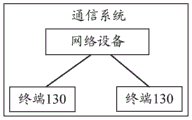
The scheduling switching method provided by the embodiment of the application can be used for a communication system supporting multiple scheduling modes, such as: can be suitably used for the fourth generation (4)thgeneration, 4G) system, Long Term Evolution (LTE) system, fifth generation (5th generation, 5G) system, New Radio (NR) system, and any of the vehicle-to-any communication (V2X) systems, and may be applied to other next-generation communication systems, and the like, without limitation. The method provided by the embodiment of the present application is described below by taking the communication system shown in fig. 3 as an example.
Fig. 3 is a schematic diagram of a communication system according to an embodiment of the present application, and as shown in fig. 3, the communication system may include a network device and a plurality of terminals (e.g., terminal 1, terminal 2). The terminal can be located in the coverage area of the network equipment and connected with the network equipment. In the system shown in fig. 3, the terminal may receive the PDCCH sent by the network device, and send the PUSCH to the network device or receive the PDSCH sent by the network device under the indication of the DCI included in the PDCCH, or receive the CSI-RS sent by the network device or report the SRS to the network device under the indication of the DCI included in the PDCCH.
The network device is mainly used for realizing the functions of resource scheduling, radio resource management, radio access control and the like of the terminal. Specifically, the network device may be any one of a small base station, a wireless access point, a transmission point (TRP) Transmission Point (TP), and some other access node. In the embodiment of the present application, the apparatus for implementing the function of the network device may be a network device, or may be an apparatus or a functional module, such as a chip system, capable of supporting the network device to implement the function. The following describes a scheduling switching method provided in an embodiment of the present application, by taking a device for implementing a function of a network device as an example.
The terminal may be a terminal equipment (terminal equipment), a User Equipment (UE), a Mobile Station (MS), a Mobile Terminal (MT), or the like. Such as: the terminal in fig. 3 may be a mobile phone (mobile phone), a tablet computer or a computer with a wireless transceiving function, and may also be a Virtual Reality (VR) terminal, an Augmented Reality (AR) terminal, a wireless terminal in industrial control, a wireless terminal in unmanned driving, a wireless terminal in telemedicine, a wireless terminal in a smart grid, a wireless terminal in a smart city (smart city), a smart home, a vehicle-mounted terminal, and the like. In the embodiment of the present application, the apparatus for implementing the function of the terminal may be the terminal, or may be an apparatus capable of supporting the terminal to implement the function, such as a chip system. In the following, a scheduling switching method provided in an embodiment of the present application is described by taking a device for implementing a function of a terminal as an example.
In the system shown in fig. 3, the network device may send a handover instruction to the terminal, instructing the terminal to switch from the first scheduling manner to the second scheduling manner, for example: and switching from the synchronous slot scheduling to the cross-time slot scheduling, or switching from the cross-time slot scheduling to the synchronous slot scheduling, after the terminal receives a switching instruction, determining the effective time of the second scheduling mode, and scheduling the data channel and/or triggering the reference signal by adopting the second scheduling mode when the effective time of the second scheduling mode arrives. Especially, under the condition that the second scheduling mode is cross-time slot scheduling, the terminal closes the radio frequency module of the terminal so as to achieve the purpose of energy conservation. Specifically, the process may be described with reference to the corresponding embodiment of fig. 5.
It should be noted that fig. 3 is only an exemplary framework diagram, the number of nodes included in fig. 3 is not limited, and the communication system shown in fig. 3 may include other nodes besides the functional nodes shown in fig. 3, such as: core network devices, gateway devices, application servers, etc., without limitation.
In particular implementations, the terminal shown in fig. 4 may adopt the constituent structure shown in fig. 4 or include the components shown in fig. 4.
Fig. 4 is a schematic composition diagram of a communication apparatus 400 according to an embodiment of the present application, where the communication apparatus 400 may be a terminal or a chip in the terminal or a system on a chip. The communication device 400 may include a processor 401, a communication line 402, and a communication interface 403. Further, the communication device 400 may also include a memory 404. The processor 401, the memory 404 and the communication interface 403 may be connected by a communication line 402.
The processor 401 may be a Central Processing Unit (CPU), a general purpose processor Network (NP), a Digital Signal Processor (DSP), a microprocessor, a microcontroller, a Programmable Logic Device (PLD), or any combination thereof. The processor 401 may also be other means having processing functionality, such as a circuit, a device, a software module, or the like.
A communication line 402 for transmitting information between the respective components included in the communication apparatus 400.
A communication interface 403 for communicating with other devices or other communication networks. The other communication network may be an ethernet network, a Radio Access Network (RAN), a Wireless Local Area Network (WLAN), or the like. The communication interface 403 may be a radio frequency module, a transceiver, or any device capable of enabling communication. The embodiment of the present invention is described by taking the communication interface 403 as an rf module as an example, where the rf module may include an antenna, an rf circuit, and the like, and the rf circuit may include an rf integrated chip, a power amplifier, and the like.
A memory 404 for storing instructions. Wherein the instructions may be a computer program.
The memory 404 may be a read-only memory (ROM) or other types of static storage devices that can store static information and/or instructions, a Random Access Memory (RAM) or other types of dynamic storage devices that can store information and/or instructions, an electrically erasable programmable read-only memory (EEPROM), a compact disc read-only memory (CD-ROM) or other optical disc storage, optical disc storage (including compact disc, laser disc, optical disc, digital versatile disc, blu-ray disc, etc.), a magnetic disc storage medium or other magnetic storage devices, and the like.
It is to be noted that the memory 404 may exist independently from the processor 401 or may be integrated with the processor 401. The memory 404 may be used for storing instructions or program code or some data or the like. The memory 404 may be located within the communication device 400 or may be located outside the communication device 400, without limitation.
The processor 401 is configured to execute the instructions stored in the memory 404 to implement the scheduling switching method provided in the following embodiments of the present application. For example, when the communication apparatus 400 is a terminal or a chip or a system on a chip in a terminal, the processor 401 may execute instructions stored in the memory 404 to implement the steps performed by the terminal in the embodiments described below in the present application. As another example, when the communication apparatus 400 is a functional entity or a chip or a system on a chip in a functional entity, the processor 401 may execute instructions stored in the memory 404 to implement the steps performed by the functional entity in the embodiments described below in the present application.
In one example, processor 401 may include one or more CPUs, such as CPU0 and CPU1 in fig. 4.
As an alternative implementation, the communication device 400 includes multiple processors, for example, the processor 407 may be included in addition to the processor 401 in fig. 4.
As an alternative implementation, the communication apparatus 400 further includes an output device 405 and an input device 406. Illustratively, the input device 406 is a keyboard, mouse, microphone, joystick, or the like, and the output device 405 is a display, speaker (microphone), or the like.
It should be noted that the communication apparatus 400 may be a desktop computer, a portable computer, a network server, a mobile phone, a tablet computer, a wireless terminal, an embedded device, a chip system, or a device with a similar structure as that in fig. 4. Further, the constituent structure shown in fig. 4 does not constitute a limitation of the communication apparatus, and the communication apparatus may include more or less components than those shown in fig. 4, or combine some components, or a different arrangement of components, in addition to the components shown in fig. 4.
In the embodiment of the present application, the chip system may be composed of a chip, and may also include a chip and other discrete devices.
In addition, acts, terms, and the like referred to between the embodiments of the present application may be mutually referenced and are not limited. In the embodiment of the present application, the name of the message or the name of the parameter in the message exchanged between the devices is only an example, and other names may also be used in the specific implementation, which is not limited. For example, the switching indication in the following embodiments may also be described as a power saving signal (power saving signal) or the like, without limitation.
The following describes a scheduling handover method provided in the embodiment of the present application with reference to the communication system shown in fig. 3.
Fig. 5 is a flowchart of a scheduling switching method provided in an embodiment of the present application, and as shown in fig. 5, the method may include steps 501 to 502:
step 501: the network equipment sends a switching instruction to the terminal.
The network device may be the network device in fig. 3, and the terminal may be any terminal in the system shown in fig. 3.
The switching indication may be used to indicate that the terminal switches from the first scheduling manner to the second scheduling manner. The first scheduling mode is different from the second scheduling mode, the first scheduling mode can be the same time slot scheduling, and the second scheduling mode can be the cross-time slot scheduling; or, the first scheduling mode is cross-slot scheduling, and the second scheduling mode is simultaneous-slot scheduling, or both the first scheduling mode and the second scheduling mode are cross-slot scheduling, but a time slot difference between a time slot occupied by the PDCCH in the first scheduling mode and a time slot occupied by a data channel scheduled by the PDCCH is different from a time slot difference between a time slot occupied by the PDCCH in the first scheduling mode and a time slot occupied by a data channel scheduled by the PDCCH, such as: the value of K0 is 1 in the first scheduling mode, and the value of K0 is 2 in the second scheduling mode, which is not limited in this application. The related descriptions of the simultaneous slot scheduling and the cross slot scheduling can refer to the above, and are not described again.
In one possible design, the switching indication may include an indicator explicitly indicating the second scheduling manner, where the indicator may be a binary bit number, such as: when the switching indication comprises binary bit 0, the scheduling mode of the terminal is represented as the slotted scheduling, and when the switching indication comprises binary bit 1, the scheduling mode of the terminal is represented as the cross-slotted scheduling.
In yet another possible design, the switching indication may include a parameter value corresponding to the second scheduling manner, such as: the switching indication may include any one or more of the following parameter values: the terminal can determine which scheduling mode to switch to through parameter values included by the switching indication. For example, if the handover indication includes a minimum K0 value and the minimum K0 value is greater than 0, it is determined that the terminal will switch to cross-slot scheduling, and if the handover indication includes a minimum K0 value and the minimum K0 value is equal to 0, it is determined that there may be both simultaneous scheduling and cross-slot scheduling. If the switch indication includes a value of K0 and the value of K0 is equal to 0, then it is determined that the terminal will switch to slotted scheduling.
In yet another possible design, the handover indication may include an index value (index), which may be used to indicate the second scheduling manner, such as: the index value (index) may correspond to a minimum K0 value, a minimum K2 value, a minimum aperiodic CSI-RS trigger offset value, or a minimum aperiodic SRS trigger offset value, and the terminal may determine the minimum K0 value, the minimum K2 value, the minimum aperiodic CSI-RS trigger offset value, or the minimum aperiodic SRS trigger offset value by the index value, and then determine a scheduling mode of the terminal according to the minimum K0 value, the minimum K2 value, the minimum aperiodic CSI-RS trigger offset value, or the minimum aperiodic SRS trigger offset value.
Illustratively, the network device may send the handover indication to the terminal over a communication link between the network device and the terminal. Specifically, the handover indication may be sent to the terminal through the PDCCH, for example: the handover indication may be sent to the terminal through a certain field in DCI transmitted through the PDCCH, or the handover indication may also be sent to the terminal through other signaling, for example: the handover indication may be sent to the terminal through a media access control element (MAC CE) transmitted on the PDSCH, which is not limited in this application.
It should be noted that, in the embodiment of the present application, the naming of the handover indication is not limited, and optionally, the handover indication may also be named as other messages, for example: the switching indication may also be named a power saving signal, etc., which is not limited in this application.
Step 502: and the terminal receives the switching indication and determines the effective time of the second scheduling mode.
For example, when the handover indication is sent to the terminal through DCI transmitted through the PDCCH, the terminal may receive the PDCCH sent by the network device and obtain the handover indication from the DCI included in the PDCCH; when the handover indication is sent to the terminal through the MAC CE transmitted on the PDSCH, the terminal may receive the PDSCH sent by the network device, and obtain the handover indication from the MAC CE included in the PDSCH.
The effective time of the second scheduling mode may refer to a time when the terminal may schedule a data channel (e.g., PDSCH, PUSCH) and/or trigger a reference signal (e.g., CSI-RS, SRS) by using the second scheduling mode; or the time when the second scheduling mode starts to take effect. When the effective time of the second scheduling manner arrives, or after the effective time of the second scheduling manner arrives and before the next handover indication arrives, the terminal may adjust its own functional module (e.g., a radio frequency module, a processing module for demodulating PDCCH, etc.), and schedule the data channel and/or trigger the reference signal using the second scheduling manner. For example, when the second scheduling manner is cross-slot scheduling, the terminal may close its radio frequency module after the effective time of the second scheduling manner (including the effective time of the second scheduling manner), so as to achieve the purpose of saving power for the terminal.
In the embodiment of the present application, in order to ensure the reliability of the transmission of the handover indication, the reliability of the data channel transmitted between the terminal and the network device, and the like, the effective time of the second scheduling method may be determined according to one or more factors, such as whether the terminal correctly receives the PDCCH, whether the terminal correctly receives the data channel scheduled by the PDCCH, and the capability of the terminal itself to process the PDCCH. Specifically, the determination process of the effective time of the second scheduling method may be described with reference to the following first to seventh methods.
Based on the method shown in fig. 5, after receiving the handover instruction, the terminal may determine the effective time of the handed-over scheduling manner, so that when the terminal arrives at the effective time of the second scheduling manner, the terminal schedules the data channel and/or triggers the reference signal in the second scheduling manner, and especially when the second scheduling manner is cross-slot scheduling, if the terminal desires to be in the energy saving state, the terminal may close its radio frequency module in a certain time period after the effective time of the second scheduling manner (e.g., a time period after the terminal receives the PDCCH of the scheduling data and before the PDCCH is demodulated), so as to enter the energy saving state.
Several possible values of the effective time of the second scheduling mode are described below with reference to the following modes one to six:
The first method is as follows: the handover indication is included in a PDCCH, which may not be used for scheduling a data channel and/or a trigger reference signal, but also may be used for scheduling a data channel and/or a trigger reference signal, which is not limited in this application.
The handover indication included in the PDCCH may also be described as a handover indication carried on the PDCCH, or the handover indication is sent to the terminal through the PDCCH, or the handover indication is included in DCI in the PDCCH and is a field in the DCI, or the handover indication is sent to the terminal through the DCI on the PDCCH, or the handover indication is DCI in the PDCCH, and the like, which is not limited in this application.
In the first mode, in order to ensure reliability (or accuracy) of a handover indication included in a PDCCH, the PDCCH may correspond to feedback information, and once the terminal receives the PDCCH, the terminal feeds back a reception condition of the PDCCH to the network device, so that the network device knows whether the terminal correctly receives the PDCCH, and if the network device knows that the terminal does not correctly receive the PDCCH, the PDCCH including the handover indication is retransmitted.
Feedback information corresponding to the PDCCH including the handover indication may be referred to as feedback information of the PDCCH, the feedback information of the PDCCH may be included in the PUCCH or the PUSCH, the feedback information of the PDCCH may occupy one or more symbols in one slot, and one symbol may occupy tens of microseconds (us). Feedback information of the PDCCH may be used to indicate whether the terminal correctly receives the PDCCH including the handover indication, and the feedback information of the PDCCH may be an Acknowledgement (ACK) or a non-acknowledgement (NACK) message. And if the terminal correctly receives the PDCCH, sending ACK to the network equipment, otherwise, if the terminal incorrectly receives the PDCCH comprising the switching indication, sending NACK to the network equipment so that the network equipment retransmits the switching indication to ensure the reliability of the switching indication comprised by the PDCCH. For example: the terminal may use a Cyclic Redundancy Check (CRC) method to verify whether it correctly receives the PDCCH including the handover indication, which is not described in detail.
In order to avoid the problem that the reliability of the handover indication included in the PDCCH is reduced because the terminal cannot transmit the feedback information of the PDCCH to the network device, in the first scheme, the effective time of the second scheduling scheme may be after the feedback information of the PDCCH including the handover indication is transmitted.
Specifically, the effective time of the second scheduling mode may be designed as shown in (1.1) or (1.2) or (1.3) below:
(1.1) the effective time of the second scheduling mode is a symbol (symbol) next to a last symbol occupied by the feedback information of the PDCCH.
The next symbol of the last symbol occupied by the feedback information of the PDCCH may be a symbol adjacent to the last symbol occupied by the feedback information of the PDCCH, or may be any symbol after the last symbol occupied by the feedback information of the PDCCH, which is not limited in this application.
The symbol described in the embodiment of the present application has a certain length, and the time length of one symbol may be several tens of micro seconds (us), such as: the time length of one symbol may be 71 us. When the time length of one symbol is several tens of us, the effective time of the second scheduling method, which is the next symbol of the last symbol occupied by the feedback information of the PDCCH, may include: the effective time of the second scheduling mode is the starting time of the next symbol of the last symbol occupied by the feedback information of the PDCCH, or any other time in the next symbol of the last symbol occupied by the feedback information of the PDCCH, such as: may be the qth us of the next symbol of the last symbol occupied by the feedback information of the PDCCH, where Q is a positive integer.
For example, taking an example that each slot includes 14 symbols, as shown in fig. 6a, the terminal receives the PDCCH including the handover indication at the 1 st symbol of slot1, and sends the feedback information of the PDCCH including the handover indication to the network device at the 12 th symbol of slot1, then as shown by a dotted line in fig. 6a, the effective time of the second scheduling mode may be the 13 th symbol or the 14 th symbol after the 12 th symbol in slot 1. Taking the effective time of the second scheduling manner as the 13 th symbol in slot1 and the time length of each symbol as an example, the effective time of the second scheduling manner may specifically be the 1 st us of the 13 th symbol, may also be the 50 th us of the 13 th symbol, and may also be the 71 th us of the 13 th symbol, which is not limited in the present application.
And (1.2) the effective time of the second scheduling mode is the next time slot of the time slot occupied by the feedback information of the PDCCH.
The next time slot of the time slot occupied by the feedback information of the PDCCH may be a time slot adjacent to the time slot occupied by the feedback information of the PDCCH after the time slot occupied by the feedback information of the PDCCH, or may be any time slot after the time slot occupied by the feedback information of the PDCCH, which is not limited in this application.
The timeslot described in this embodiment of the present application may include a plurality of symbols, such as: one slot may include 12 or 14 symbols, etc. When one time slot includes a plurality of symbols, the effective time of the second scheduling method may be the next time slot of the time slot occupied by the feedback information of the PDCCH: the effective time of the second scheduling mode is a starting symbol of a next time slot of a time slot occupied by the feedback information of the PDCCH, or other arbitrary symbols in the next time slot of the time slot occupied by the feedback information of the PDCCH, such as: the symbol may be an R-th symbol in a next slot of a slot occupied by feedback information of the PDCCH, where R is a positive integer. Or, when one slot includes a plurality of symbols, and the time length of one symbol is several tens of us, the next slot of the slot occupied by the feedback information of the PDCCH, where the effective time of the second scheduling mode is the effective time, may include: the effective time of the second scheduling mode is the starting time of a certain symbol (such as a starting symbol or any other symbol, such as the R-th symbol) in the next time slot of the time slot occupied by the feedback information of the PDCCH, or the effective time of the second scheduling mode is any other time in a certain symbol in the next time slot of the time slot occupied by the feedback information of the PDCCH, such as: the qth us in a certain symbol, Q is an integer, etc.
For example, taking an example that each slot includes 14 symbols, as shown in fig. 6b, the terminal receives the PDCCH including the handover indication in the 1 st symbol of slot1, and sends the feedback information of the PDCCH including the handover indication to the network device in slot1, then as shown by a dotted line in fig. 6b, the effective time of the second scheduling mode may be the next slot of slot 1: slot 2. Such as: when a slot includes 14 symbols, the effective time of the second scheduling manner may be the 1 st symbol in slot2, may also be the 10 th symbol in slot2, may also be the 14 th symbol in slot2, and the like, or, when the time length of each symbol is several tens of us, the effective time of the second scheduling manner may be the 1 st us of the 1 st symbol in slot2, may also be the 10 th us of the 1 st symbol in slot2, and may also be the 50 th us of the 1 st symbol in slot2, and the like.
And (1.3) the effective time of the second scheduling mode is the first scheduling information monitoring opportunity behind the time domain position occupied by the feedback information of the PDCCH.
The scheduling information monitoring occasion (scheduling information monitoring occasion) may be an occasion for a terminal to monitor a PDCCH for scheduling a data channel, and the scheduling information monitoring occasion may occupy one symbol or multiple symbols in a time slot, which is not limited in this application. The terminal may start monitoring the PDCCH for scheduling the data channel when the scheduling information monitoring occasion comes. In practical application, a network device may configure a plurality of scheduling information monitoring time slots for a terminal, and one or more time slots are spaced between two adjacent scheduling information monitoring time slots, so that the terminal periodically monitors a PDCCH for scheduling a data channel.
In order to avoid the problem that the terminal cannot monitor the PDCCH of the scheduling data channel, and the data channel cannot be correctly transmitted, the second scheduling mode takes effect when the monitoring opportunity of the first scheduling information after the time domain position occupied by the feedback information of the PDCCH comes. When the first scheduling information monitoring occasion occupies multiple symbols, the first scheduling information monitoring occasion whose effective time is after the time domain position occupied by the feedback information of the PDCCH in the second scheduling manner may include: the effective time of the second scheduling mode is a starting symbol of the first scheduling information monitoring occasion after the time domain position occupied by the feedback information of the PDCCH, and may also be any other symbol in the first scheduling information monitoring occasion.
When the first scheduling information monitoring opportunity occupies a plurality of symbols, and each symbol occupies tens of us, the first scheduling information monitoring opportunity whose effective time of the second scheduling mode is after the time domain position occupied by the feedback information of the PDCCH may include: the effective time of the second scheduling manner is a starting time of a certain symbol (e.g., a starting symbol or any other symbol) in the first scheduling information monitoring opportunity after the time domain position occupied by the feedback information of the PDCCH, or the effective time of the second scheduling manner is another any time of a certain symbol (e.g., a starting symbol or any other symbol) in the first scheduling information monitoring opportunity after the time domain position occupied by the feedback information of the PDCCH, which is not limited in this application.
It should be noted that, in (1.3), the first scheduling information monitoring occasion after the time domain position occupied by the feedback information of the PDCCH may be a scheduling information monitoring occasion that appears for the first time after the time domain position occupied by the feedback information of the PDCCH, or may be any other scheduling information monitoring occasion after the time domain position occupied by the feedback information of the PDCCH, such as: the scheduling information monitoring time may be an nth scheduling information monitoring time after a time domain position occupied by feedback information of the PDCCH, where N is a positive integer.
For example, taking an example that each slot includes 14 symbols, as shown in fig. 6c, the terminal receives the PDCCH including the handover indication at the 1 st symbol of slot1, and sends the feedback information of the PDCCH including the DCI to the network device at slot1, where a first scheduling information monitoring opportunity after a time domain position occupied by the feedback information of the PDCCH including the DCI is located at slot3, and as shown by a dotted line in fig. 6c, an effective time of the second scheduling manner may be slot 3. Taking the example that each slot includes 14 symbols, the effective time of the second scheduling mode may be the starting symbol of slot3, such as: the 1 st symbol in slot3 may also be the 10 th symbol in slot3, may also be the 14 th symbol in slot3, and the like, or, taking the time length of each symbol as tens of us as an example, the effective time of the second scheduling manner may be the 1 st us of the 1 st symbol in slot3, may also be the 10 th us of the 1 st symbol in slot3, and may also be the 50 th us of the 1 st symbol in slot3, and the like.
In the second mode, the handover indication is included in the PDCCH, and the PDCCH may include scheduling information in addition to the handover indication, where the scheduling information is used for scheduling a downlink data channel (e.g., PDSCH) of the terminal.
The handover indication included in the PDCCH may also be described as a handover indication carried on the PDCCH, or the handover indication is sent to the terminal through the PDCCH, or the handover indication is included in DCI in the PDCCH and is a field in DCI, or the handover indication is sent to the terminal through DCI on the PDCCH, or the handover indication is DCI in the PDCCH, and the like, which is not limited in this application.
In the second mode, in order to ensure the reliability of the downlink data channel scheduled by the PDCCH, the terminal needs to send feedback information of the downlink data channel to the network device, for example: once the terminal receives the downlink data channel scheduled by the PDCCH, the terminal feeds back the receiving condition to the network device, so that the network device knows whether the terminal correctly receives the downlink data channel scheduled by the PDCCH, and if the network device knows that the terminal does not correctly receive the downlink data channel scheduled by the PDCCH, the network device sends the downlink data channel to the terminal again, so as to ensure the reliability of downlink data channel transmission.
The feedback information of the downlink data channel may be included in a PUCCH or a PUSCH, and may occupy one or more symbols in one slot, and one symbol may occupy tens of microseconds (us). The feedback information of the downlink data channel may be used to indicate whether the terminal correctly receives the downlink data channel scheduled by the PDCCH including the handover indication, and the feedback information of the downlink data channel may be ACK or NACK. And if the terminal correctly receives the downlink data channel, sending ACK (acknowledgement) to the network equipment, otherwise, if the terminal does not correctly receive the downlink data channel, sending NACK (negative acknowledgement) to the network equipment so that the network equipment retransmits the downlink data channel to ensure the reliability of downlink data channel transmission. Specifically, the terminal may determine whether it correctly receives the downlink data channel scheduled by the PDCCH by using the prior art, and details are not described.
In order to avoid the problem that the reliability of the downlink data channel is reduced because the terminal cannot send the feedback information of the downlink data channel to the network device, in the second method, the effective time of the second scheduling method may be after the feedback information of the downlink data channel scheduled by the PDCCH is sent.
Specifically, the effective time of the second scheduling mode may be designed as shown in (2.1) or (2.2) or (2.3) below:
and (2.1) the effective time of the second scheduling mode is the next symbol of the last symbol occupied by the feedback information of the downlink data channel.
The next symbol of the last symbol occupied by the feedback information of the downlink data channel may be a symbol adjacent to the last symbol occupied by the feedback information of the downlink data channel, or may be any symbol after the last symbol occupied by the feedback information of the downlink data channel, which is not limited in this application.
When the time length of one symbol is several tens of us, the effective time of the second scheduling mode is the next symbol of the last symbol occupied by the feedback information of the downlink data channel, and the effective time of the second scheduling mode may include: the effective time of the second scheduling mode is the starting time of the next symbol of the last symbol occupied by the feedback information of the downlink data channel, or other times in the next symbol of the last symbol occupied by the feedback information of the downlink data channel, such as: may be the qth us in the next symbol of the last symbol occupied by the feedback information of the downlink data channel, where Q is a positive integer.
For example, taking that each slot includes 14 symbols as an example, as shown in fig. 7a, the terminal monitors a PDCCH including a handover indication in a 1 st symbol of a slot0, and a downlink data channel scheduled by the PDCCH is located in a slot0, feedback information of the downlink data channel is in a 12 th symbol of a slot1, as shown by a dotted line in fig. 7a, an effective time of the second scheduling mode may be a next symbol after the 12 th symbol in the slot1, such as: the 13 th symbol or the 14 th symbol in slot1, etc. Taking the effective time of the second scheduling manner as the 13 th symbol in slot1 and the time length of each symbol as an example, the effective time of the second scheduling manner may specifically be the starting time of the 13 th symbol, such as: the 1us of the 13 th symbol may be the 50us of the 13 th symbol, or may be the 71us of the 13 th symbol, which is not limited in the present application.
And (2.2) the effective time of the second scheduling mode is the next time slot of the time slot occupied by the feedback information of the downlink data channel.
The next time slot of the time slot occupied by the feedback information of the downlink data channel may be a time slot adjacent to the time slot occupied by the feedback information of the downlink data channel after the time slot occupied by the feedback information of the downlink data channel, or may be any time slot after the time slot occupied by the feedback information of the downlink data channel, which is not limited in this application.
The timeslot described in this embodiment of the present application may include a plurality of symbols, such as: may comprise 12 or 14 symbols, etc. When one timeslot includes a plurality of symbols, the effective time of the second scheduling method may be the next timeslot of the timeslot occupied by the feedback information of the downlink data channel, where the time effective time of the second scheduling method is: the effective time of the second scheduling mode is the initial symbol of the next time slot of the time slot occupied by the feedback information of the downlink data channel, or other arbitrary symbols in the next time slot of the time slot occupied by the feedback information of the downlink data channel, such as: the symbol may be an R-th symbol in a time slot next to the time slot occupied by the feedback information of the downlink data channel, where R is a positive integer. Or, when the time slot occupied by the feedback information of the downlink data channel includes a plurality of symbols, and the time length of each symbol is several tens of us, the effective time of the second scheduling method may be the next time slot of the time slot occupied by the feedback information of the downlink data channel: the effective time of the second scheduling mode is the starting time of a certain symbol (such as a starting symbol or any other symbol) in the next time slot of the time slot occupied by the feedback information of the downlink data channel, or other times in a certain symbol in the next time slot of the time slot occupied by the feedback information of the downlink data channel, such as: and the Q & ltth & gt us & lt/th & gt in a certain symbol in the next time slot of the time slot occupied by the feedback information of the downlink data channel is an integer.
For example, taking that each slot includes 14 symbols as an example, as shown in fig. 7b, the terminal monitors a PDCCH including a handover indication in a 1 st symbol of a slot0, and a downlink data channel scheduled by the PDCCH including the handover indication is located in a slot0, and feedback information of the downlink data channel is in a 12 th symbol of a slot1, as shown by a dotted line in fig. 7b, a validity time of the second scheduling mode may be a next slot of the slot1, and may be a start time of the slot 2. Specifically, when the slot includes 14 symbols, the effective time of the second scheduling mode may be a starting symbol in the slot2, such as: the 1 st symbol may also be the 10 th symbol in slot2, may also be the 14 th symbol in slot2, and the like, or, when the time length of each symbol is several tens of us, the effective time of the second scheduling mode may be the starting time of the 1 st symbol in slot2, such as: may be the 1 st us of the 1 st symbol in slot2, may be the 10 th us of the 1 st symbol in slot2, may be the 50 th us of the 1 st symbol in slot2, and the like.
And (2.3) the effective time of the second scheduling mode is the first scheduling information monitoring opportunity behind the time domain position occupied by the feedback information of the downlink data channel.
The description of the scheduling information monitoring time is as described in the first embodiment, and is not repeated. It should be noted that in (2.3), the first scheduling information monitoring time after the time domain position occupied by the feedback information of the downlink data channel may be a scheduling information monitoring time occurring for the first time after the time domain position occupied by the feedback information of the downlink data channel, or may be any other scheduling information monitoring time after the time domain position occupied by the feedback information of the downlink data channel, such as: the scheduling information monitoring time can be the nth scheduling information monitoring time after the time domain position occupied by the feedback information of the downlink data channel, and N is a positive integer.
In order to avoid the problem that the terminal cannot monitor the PDCCH of the scheduling data channel, which causes the data channel to be transmitted incorrectly, the second scheduling mode takes effect when the first scheduling information monitoring opportunity comes after the time domain position occupied by the feedback information of the downlink data channel.
When the first scheduling information monitoring occasion occupies multiple symbols, the first scheduling information monitoring occasion in which the effective time of the second scheduling mode is after the time domain position occupied by the feedback information of the downlink data channel may include: the effective time of the second scheduling mode is a starting symbol of the first scheduling information monitoring opportunity after the time domain position occupied by the feedback information of the downlink data channel, or is any other symbol in the first scheduling information monitoring opportunity after the time domain position occupied by the feedback information of the downlink data channel.
When the first scheduling information monitoring opportunity occupies a plurality of symbols, and each symbol occupies tens of us, the first scheduling information monitoring opportunity whose effective time of the second scheduling mode is after the time domain position occupied by the feedback information of the downlink data channel may include: the effective time of the second scheduling manner is a starting time of a certain symbol (for example, a starting symbol or any other symbol) in the first scheduling information monitoring opportunity after the time domain position occupied by the feedback information of the downlink data channel, or the effective time of the second scheduling manner is another any time of a certain symbol (for example, a starting symbol or any other symbol) in the first scheduling information monitoring opportunity after the time domain position occupied by the feedback information of the downlink data channel, which is not limited in the present application.
For example, as shown in fig. 7c, when the terminal monitors the PDCCH including the switching indication in the 1 st symbol of slot0, and the downlink data channel scheduled by the PDCCH including the switching indication is located in slot0, the feedback information of the downlink data channel is in the 12 th symbol of slot1, and the first scheduling information monitoring time after the time domain position occupied by the feedback information of the downlink data channel is located in slot3, as shown by a dotted line in fig. 7c, the effective time of the second scheduling mode may be the starting time of slot3 or other times. Taking an example that each slot includes 14 symbols, the effective time of the second scheduling manner may be the 1 st symbol in slot3, may also be the 10 th symbol in slot3, may also be the 14 th symbol in slot3, or, taking the time length of each symbol as tens of us as an example, the effective time of the second scheduling manner may be the 1 st us of the 1 st symbol in slot3, may also be the 10 th us of the 1 st symbol in slot3, may also be the 71 th us of the 1 st symbol in slot3, and so on.
In a third mode, the handover indication is included in a PDCCH, and the PDCCH may further include scheduling information in addition to the handover indication, where the scheduling information is used for scheduling an uplink data channel (e.g., PUSCH).
The handover indication included in the PDCCH may also be described as a handover indication carried on the PDCCH, or the handover indication is sent to the terminal through the PDCCH, or the handover indication is included in DCI in the PDCCH and is a field in DCI, or the handover indication is sent to the terminal through DCI on the PDCCH, or the handover indication is DCI in the PDCCH, and the like, which is not limited in this application.
In the third mode, in order to ensure the reliability of the uplink data channel scheduled by the PDCCH, the terminal needs to take effect in the second scheduling mode after receiving the uplink data channel scheduled by the PDCCH.
Specifically, the effective time of the second scheduling mode may be designed as shown in (3.1) or (3.2) or (3.3) below:
and (3.1) the effective time of the second scheduling mode is the next symbol of the last symbol occupied by the uplink data channel.
The next symbol of the last symbol occupied by the uplink data channel may be a symbol adjacent to the last symbol occupied by the uplink data channel, or may be an arbitrary symbol after the last symbol occupied by the uplink data channel, which is not limited in the present application.
When the time length of one symbol is several tens of us, the effective time of the second scheduling mode being the next symbol of the last symbol occupied by the uplink data channel may include: the effective time of the second scheduling mode is the starting time of the next symbol of the last symbol occupied by the uplink data channel, or other times in the next symbol of the last symbol occupied by the feedback information of the downlink data channel, such as: may be the qth us in the next symbol of the last symbol occupied by the feedback information of the downlink data channel, where Q is a positive integer.
For example, taking that each slot includes 14 symbols as an example, as shown in fig. 8a, the terminal monitors a PDCCH including a handover indication in a 1 st symbol of slot0, and an uplink data channel scheduled by the PDCCH including the handover indication is located in a 12 th symbol of slot0, as shown by a dotted line in fig. 8a, an effective time of the second scheduling mode may be a next symbol after the 12 th symbol in slot0, such as: the 13 th symbol or the 14 th symbol in slot0, etc. Taking the effective time of the second scheduling manner as the 13 th symbol in slot0 and the time length of each symbol as an example, the effective time of the second scheduling manner may specifically be the starting time of the 13 th symbol in slot0, such as: the 1us of the 13 th symbol may be, alternatively, the 50us of the 13 th symbol, alternatively, the 71us of the 13 th symbol, which is not limited in this application.
And (3.2) the effective time of the second scheduling mode is the next time slot of the time slot occupied by the uplink data channel.
The next time slot of the time slot occupied by the uplink data channel may be a time slot adjacent to the time slot occupied by the uplink data channel after the time slot occupied by the uplink data channel, or may be any time slot after the time slot occupied by the uplink data channel.
The timeslot described in this embodiment of the present application may include a plurality of symbols, such as: including 12 or 14 symbols, etc. When one timeslot includes a plurality of symbols, the effective time of the second scheduling method may be the next timeslot of the timeslot occupied by the uplink data channel, where the effective time is: the effective time of the second scheduling mode is a starting symbol of a next time slot of the time slot occupied by the uplink data channel, or other arbitrary symbols in the next time slot of the time slot occupied by the uplink data channel, such as: and the R-th symbol in the next time slot of the time slot occupied by the uplink data channel, wherein R is a positive integer.
When the time slot occupied by the uplink data channel includes a plurality of symbols, and the time length of each symbol is several tens of us, the effective time of the second scheduling mode may be the next time slot of the time slot occupied by the uplink data channel: the effective time of the second scheduling mode is the starting time of a certain symbol (such as a starting symbol or any other symbol) in the next time slot of the time slot occupied by the uplink data channel, or any other time in a certain symbol in the next time slot of the time slot occupied by the uplink data channel, such as: and the Q & ltth & gt us & lt/th & gt in a certain symbol in the next time slot of the time slot occupied by the uplink data channel is an integer.
For example, taking each slot including 14 slots as an example, as shown in fig. 8b, the terminal monitors a PDCCH including a handover indication in a 1 st symbol of slot0, and an uplink data channel scheduled by the PDCCH including the handover indication is located in a 12 th symbol of slot0, as shown by a dotted line in fig. 8b, an effective time of the second scheduling mode may be a next slot of slot1, such as a start time of slot 1. Specifically, when the slot includes 14 symbols, the effective time of the second scheduling mode may be the starting symbol in slot1, such as: the 1 st symbol in slot1 may also be the 10 th symbol in slot1, may also be the 14 th symbol in slot1, and the like, or when the time length of each symbol is several tens of us, the effective time of the second scheduling mode may be the starting time of the 1 st symbol in slot1, such as: may be the 1 st us of the 1 st symbol in slot1, may be the 10 th us of the 1 st symbol in slot1, may be the 71 th us of the 1 st symbol in slot1, and the like.
And (3.3) the effective time of the second scheduling mode is the first scheduling information monitoring opportunity after the time domain position occupied by the uplink data channel.
The description of the scheduling information monitoring time is as described in the first embodiment, and is not repeated. It should be noted that, in (3.3), the first scheduling information monitoring time after the time domain position occupied by the uplink data channel may be the scheduling information monitoring time that occurs for the first time after the time domain position occupied by the uplink data channel, or may be any other scheduling information monitoring time after the time domain position occupied by the uplink data channel, such as: the scheduling information monitoring time can be the Nth scheduling information monitoring time after the time domain position occupied by the uplink data channel, wherein N is a positive integer.
In order to avoid the problem that the terminal cannot monitor the PDCCH of the scheduling data channel, which causes the data channel to be transmitted incorrectly, the second scheduling mode starts to take effect when the first scheduling information monitoring opportunity after the time domain position occupied by the uplink data channel comes.
When the first scheduling information monitoring occasion occupies multiple symbols, the first scheduling information monitoring occasion, in which the effective time of the second scheduling mode is after the time domain position occupied by the uplink data channel, may include: the effective time of the second scheduling mode is the initial symbol of the first scheduling information monitoring opportunity after the time domain position occupied by the uplink data channel, or other arbitrary symbols in the first scheduling information monitoring opportunity after the time domain position occupied by the uplink data channel. Or, when the first scheduling information monitoring opportunity occupies a plurality of symbols, and each symbol occupies tens of us, the first scheduling information monitoring opportunity whose effective time of the second scheduling mode is after the time domain position occupied by the uplink data channel may include: the effective time of the second scheduling manner is a starting time of a certain symbol (e.g., a starting symbol or any other symbol) in the first scheduling information monitoring opportunity after the time domain position occupied by the uplink data channel, or the effective time of the second scheduling manner is another any time of a certain symbol (e.g., a starting symbol or any other symbol) in the first scheduling information monitoring opportunity after the time domain position occupied by the uplink data channel, which is not limited in this application.
For example, as shown in fig. 8c, the terminal monitors the PDCCH including the switching indication in the 1 st symbol of slot0, the uplink data channel scheduled by the PDCCH including the switching indication is located in the 12 th symbol of slot0, and the first scheduling information monitoring time after the time domain position occupied by the uplink data channel is located in slot2, as shown by a dotted line in fig. 8c, the effective time of the second scheduling mode may be the starting time of slot2 or other times. Taking an example that each slot includes 14 symbols, the effective time of the second scheduling manner may be the 1 st symbol in slot2, may also be the 10 th symbol in slot2, may also be the 14 th symbol in slot2, or, taking the time length of each symbol as several tens of us as an example, the effective time of the second scheduling manner may be the 1 st us of the 1 st symbol in slot2, may also be the 10 th us of the 1 st symbol in slot2, may also be the 71 th us of the 1 st symbol in slot2, and the like.
It should be noted that, in the second or third aspect, taking the PDCCH including the handover indication as an example only for scheduling the data channel, the effective time of the second scheduling aspect is described, it can be understood that, when the PDCCH including the handover indication is also used for triggering a reference signal, for example: when the CSI-RS and/or SRS is triggered, in order not to affect the triggering of the CSI-RS and/or SRS, the second scheduling method needs to be effective after the triggering of the CSI-RS and/or SRS, such as: the effective time of the second scheduling mode may be a symbol next to a last symbol occupied by the reference signal triggered by the PDCCH, or the effective time of the second scheduling mode may be a time slot next to a time slot occupied by the reference signal triggered by the PDCCH, or the effective time of the second scheduling mode may be a first scheduling information monitoring opportunity after a time domain position occupied by the reference signal triggered by the PDCCH, or the like.
In a fourth mode, the handover indication is included in the PDCCH, and the nth slot of the PDCCH is as follows: the PDCCH may occupy a certain symbol or symbols in the nth slot, N being an integer. The PDCCH including the handover indication may or may not be used for scheduling the data channel and/or the reference signal, which is not limited in this application.
In the fourth mode, the effective time of the second scheduling mode is related to the speed of the terminal for processing the PDCCH, and the speed of the terminal for processing the PDCCH is related to one or more values of a minimum K0 value, a minimum K2 value, a minimum aperiodic CSI-RS trigger offset value and a minimum aperiodic SRS trigger offset value corresponding to the PDCCH. Taking the example that the speed of processing the PDCCH by the terminal is related to the minimum K0 value corresponding to the PDCCH, when the minimum K0 value is larger, the speed of processing the PDCCH by the terminal is slower, and the effective time of the second scheduling mode is later relatively; when the minimum K0 value is small, the speed of processing the PDCCH by the terminal is fast, and the effective time of the second scheduling method is relatively earlier.
Specifically, the effective time of the second scheduling mode may be designed as shown in (4.1) or (4.2) below:
and (4.1) the effective time of the second scheduling mode is the (N + M) th time slot.
Where N may be used to indicate a slot position occupied by the PDCCH. Specifically, N may be an index number corresponding to a time slot occupied by the PDCCH. Such as: if the slot occupied by the PDCCH is slot0, N is 0.
Such as: when each slot includes a plurality of symbols, the taking effect time of the second scheduling method for the N + M th slots may include: the effective time of the second scheduling mode is the starting symbol of the N + M th slot, or any other symbol in the N + M th slot, such as: may be the R-th symbol in the N + M-th slot, R being an integer. Or, when the time length of each symbol is several tens of us, the time of the second scheduling method taking into effect as the N + M th time slot may include: the effective time of the second scheduling method is the starting time of a certain symbol (such as a starting symbol or any other symbol) in the N + M th slot, or any other time in a certain symbol in the N + M th slot, such as: may be the qth us in a symbol in the (N + M) th slot, Q being an integer.
And (4.2) the effective time of the second scheduling mode is not earlier than the first scheduling information monitoring opportunity of the (N + M) th time slot.
The description of the scheduling information monitoring time is as described in the first embodiment, and is not repeated.
When the first scheduling information monitoring opportunity occupies a plurality of symbols, the second scheduling method may take effect no earlier than the first scheduling information monitoring opportunity of the N + M th time slot: the effective time of the second scheduling mode is not earlier than the starting symbol of the first scheduling information monitoring opportunity of the (N + M) th time slot, or not earlier than any other symbol in the first scheduling information monitoring opportunity of the (N + M) th time slot. Or, when the first scheduling information monitoring opportunity occupies a plurality of symbols, each symbol occupying tens of us, the second scheduling manner may take effect no earlier than the first scheduling information monitoring opportunity of the N + M th time slot: the effective time of the second scheduling manner is not earlier than the starting time of a certain symbol (e.g., a starting symbol or any other symbol) in the first scheduling information monitoring opportunity of the N + M th time slot, or the effective time of the second scheduling manner is not earlier than any other time of a certain symbol (e.g., a starting symbol or any other symbol) in the first scheduling information monitoring opportunity of the N + M th time slot, which is not limited in this application.
Wherein, M is determined according to a minimum value (min value) of a time slot difference that is effective when the terminal receives the handover indication, where the time slot difference refers to a time slot difference between a time slot occupied by a PDCCH for scheduling a data channel (and/or a reference signal) and a time slot occupied by the data channel (and/or the reference signal) scheduled by the PDCCH, such as: the minimum value may be a minimum K0 value, or a minimum K2 value, or a minimum aperiodic CSI-RS trigger offset value, or a minimum aperiodic SRS trigger offset value, etc. M does not correspond to a slot earlier than the slot corresponding to the minimum value. Illustratively, the terminal may be indicated with a minimum value in conjunction with a TDRA table configured by the network device, such as: the network device may configure a TDRA table for the terminal and indicate a plurality of index values in the TDRA table to the terminal, so that the terminal determines a minimum value from among a plurality of values in the TDRA table corresponding to the plurality of index values. For example, the TDRA table configured by the network device for the terminal is as shown in table one above, and the network device indicates the first three rows in the TDRA table to the terminal: if index0, index1 and index2 are all valid, the minimum value is 0 according to the first lookup table.
Specifically, the relationship between M and the minimum value may be as described below (4.2.1) or (4.2.2) or (4.2.3):
(4.2.1) M equals the minimum value.
When the effective time of the second scheduling manner is defined by taking the time slot as granularity, the effective time of the second scheduling manner may be the N + M time slots after the nth time slot. Such as: if the slot occupied by the PDCCH including the switching indication is slot0 and the minimum value is 2, the effective time of the second scheduling method is slot 2.
It should be noted that, when each time slot includes a plurality of symbols, and the effective time of the second scheduling manner is defined by taking the symbols as granularity, M may be equal to a product of a minimum value and (the number of symbols included in each time slot), and at this time, the effective time of the second scheduling manner may be a certain symbol which is obtained by multiplying (the number of symbols included in each time slot) a minimum value of an interval between a last symbol occupied by the PDCCH including the handover indication and a last symbol occupied by the PDCCH including the handover indication by a symbol. Such as: if the PDCCH including the handover indication occupies slot0, and the last symbol occupied by the PDCCH is the 5 th symbol in slot0, the minimum value is 2, and each slot includes 14 symbols, the effective time of the second scheduling method may be 28 symbols apart from the 5 th symbol in slot0, and the effective time of the second scheduling method may be the 10 th symbol in slot 2.
(4.2.2) M is equal to the sum of the minimum value and the first value.
The first value may be referred to as effective time added delay, the first value may be in units of time slots, and the first value may be 1 time slot. The first value may also be in units of symbols, such as: the first value may be 14 symbols or 12 symbols, etc.
When the effective time of the second scheduling manner is defined by taking the time slot as granularity, the first value is taken as a unit of the time slot, and the effective time of the second scheduling manner may be the (N + minimum value + first value) time slot after the nth time slot. Such as: if the slot occupied by the PDCCH including the switching indication is slot0, the minimum value is 2, and the first value is 1, the effective time of the second scheduling method is slot 3.
It should be noted that, when each time slot includes a plurality of symbols, and the effective time of the second scheduling manner is defined by taking the symbols as granularity, the first value is in units of the symbols, and M may be equal to a minimum value multiplied by (the number of symbols included in each time slot) + the first value, at this time, the effective time of the second scheduling manner may be a certain symbol which is after a last symbol occupied by the PDCCH including the handover indication and is multiplied by (the number of symbols included in each time slot) + the first value, with a minimum value of a last symbol interval occupied by the PDCCH including the handover indication. Such as: if the PDCCH including the handover indication occupies slot0, and the last symbol occupied by the PDCCH is the 5 th symbol in slot0, the minimum value is 2, each slot includes 14 symbols, and the first value is 12 symbols, the effective time of the second scheduling method may be 40 symbols apart from the 5 th symbol in slot0, and the effective time of the second scheduling method may be the 8 th symbol in slot 3.
(4.2.3) M corresponds to a time slot no earlier than the time slot corresponding to the minimum value and M corresponds to a time slot no earlier than the time slot corresponding to the second value. Specifically, M may be the maximum value of the second value and the minimum value.
The second value may be referred to as a handover minimum value, the second value is related to the demodulation capability of the PDCCH of the terminal itself, and the stronger the demodulation capability of the terminal is, the smaller the second value may be, the weaker the demodulation capability of the terminal is, and the larger the second value may be. The second value is also related to the subcarrier interval currently configured by the terminal, and the smaller the subcarrier interval is, the longer the time slot length is, the smaller the second value may be; a larger subcarrier spacing means that the shorter the slot length, the larger the second value may be.
The second value may be in units of time slots, such as: the second value may be 1 (slot) or other value. The first value may also be in units of symbols, such as: the first value may be 14 symbols or 12 symbols, etc.
When the effective time of the second scheduling manner is defined by taking the time slot as the granularity, the second value is taken as the unit of the time slot, and the effective time of the second scheduling manner may be max (second value, minimum value) time slot after the nth time slot. Such as: if the slot occupied by the PDCCH including the switching indication is slot0, the minimum value is 2, and the second value is 1, the lifetime of the second scheduling method is slot 2.
It should be noted that, when each slot includes a plurality of symbols, and the effective time of the second scheduling manner is defined by taking the symbols as granularity, the second value is in units of symbols, M may be equal to max (the second value, the minimum value is multiplied by (the number of symbols included in each slot), and at this time, the effective time of the second scheduling manner may be some symbol of max (the second value, the minimum value is multiplied by (the number of symbols included in each slot) symbols after the last symbol occupied by the PDCCH including the handover indication and the last symbol occupied by the PDCCH including the handover indication, such as if the PDCCH including the handover indication occupies slot0, and the last symbol occupied by the PDCCH is the 5 th symbol in slot0, the minimum value is 2, each slot includes 14 symbols, and the second value is 12 symbols, the effective time of the second scheduling manner is 28 symbols apart from the 5 th symbol in slot0, the effective time of the second scheduling mode may be the 10 th symbol in slot 2.
For example, as shown in fig. 9a, when the terminal monitors scheduling information at slot0 and slot3, receives a PDCCH including a handover indication at the 10 th symbol of slot1, and receives the PDCCH including the handover indication, the minimum K0 value that takes effect is 0. Assuming that the second value is slot granularity, the second value is 1 (number of symbols), and M ═ max (1, minimum K0 value) ═ 1, the effective time of the second scheduling method may be slot2, which is the 1+1 st slot; alternatively, the first schedule information monitoring time is in effect no earlier than slot 2. Alternatively, assuming that M is the minimum K0 value +1 is 1, the effective time of the second scheduling method may be the 1+1 st slot, i.e., slot 2; alternatively, the first schedule information monitoring time not earlier than slot2 takes effect. Assuming that the second value is in symbol granularity, the effective time of the second scheduling manner is in symbol granularity, the second value is 5 symbols, the first value is 8 symbols, and each slot includes 14 symbols, then M ═ max (5, 0) ═ 5, the effective time of the second scheduling manner may be the 1 st symbol in slot2, or assuming that M ═ minimum K0 value is multiplied by the number of symbols included in each slot +8 ═ 8, the effective time of the second scheduling manner may be the 4 th symbol in slot 2.
For another example, as shown in fig. 9b, where the terminal monitors scheduling information at slot0, slot2, and slot4, receives a PDCCH including a handover indication at the 10 th symbol of slot1, and receives the PDCCH including the handover indication, the minimum K0 value that takes effect is 2. Assuming that the second value is slot granularity, the second value is 1, and M is max (1, minimum K0 value) is 2, the effective time of the second scheduling method may be 1+2 th slot, i.e., slot 3; alternatively, the first schedule information monitoring time is active no earlier than slot 3. Or, assuming that M is the minimum K0 value +1 is 3, the effective time of the second scheduling method may still be the 1+2 th slot, that is, slot 3; alternatively, the first schedule information monitoring time not earlier than slot3 takes effect. Assuming that the second value is in symbol granularity, the effective time of the second scheduling manner is in symbol granularity, the second value is 5 symbols, the first value is 8 symbols, and each slot includes 14 symbols, then M ═ max (5, 2 times 14) ═ 28, the effective time of the second scheduling manner may be the 10 th symbol in slot3, or, assuming that M ═ minimum K0 value times the number of symbols included in each slot +8 ═ 28+8 ═ 36, the effective time of the second scheduling manner may be the 4 th symbol in slot 4.
It should be noted that, in the fourth mode, when the PDCCH including the handover indication is not used for scheduling the data channel and/or the reference signal, the effective time of the second scheduling mode is independent of the time domain position occupied by the feedback information of the PDCCH, or the effective time of the second scheduling mode is related to the time domain position occupied by the feedback information of the PDCCH, and the effective time of the second scheduling mode takes the latest time of the time domain position occupied by the feedback information of the PDCCH and the effective time determined in (4.1) or (4.2) in the fourth mode as the criterion, and takes the second scheduling time after the latest time.
When the PDCCH including the switching indication is used for scheduling the downlink data channel, the effective time of the second scheduling mode is irrelevant to a time domain occupied by feedback information of the downlink data channel scheduled by the PDCCH, or the effective time of the second scheduling mode is relevant to a time domain position occupied by the feedback information of the downlink data channel scheduled by the PDCCH, and the effective time of the second scheduling mode takes the latest time of the time domain position occupied by the feedback information of the downlink data channel scheduled by the PDCCH and the effective time determined by the mode (4.1) or (4.2) as the criterion, and takes the second scheduling time after the latest time.
When the PDCCH including the switching indication is used for scheduling the uplink data channel, the effective time of the second scheduling mode is irrelevant to the time domain position occupied by the uplink data channel scheduled by the PDCCH, or the effective time of the second scheduling mode is relevant to the time domain position occupied by the uplink data channel scheduled by the PDCCH, and the effective time of the second scheduling mode takes the latest time of the time domain position occupied by the uplink data channel scheduled by the PDCCH and the effective time determined in the mode (4.1) or (4.2) as the standard, and takes the second scheduling time to take effect after the latest time.
In a fifth mode, the handover indication is included in a media access control element (MAC CE), and the MAC CE is included in the PDSCH.
The MAC CE included in the PDSCH may also be described as being carried on the PDSCH, or the MAC CE is sent to the terminal through the PDSCH, which is not limited in this application.
In the fifth mode, in order to ensure that the terminal receives the MAC CE and further obtains the scheduling mode indicated by the switching indication according to the received MAC CE, the second scheduling mode needs to take effect after the time slot occupied by the feedback information of the PDSCH, such as: the effective time of the second scheduling mode is after the time slot occupied by the feedback information of the PDSCH, and the effective time of the second scheduling mode is separated from the time slot occupied by the feedback information of the PDSCH by a first time length; or, the effective time described as the second scheduling manner is after a first time length after a time slot occupied by feedback information of the PDSCH.
The feedback information of the PDSCH is used to indicate whether the terminal correctly receives the PDSCH. The first duration is related to a time from when the physical layer of the terminal receives the PDSCH to when the MAC CE included in the PDSCH is transmitted to the MAC layer of the terminal. For example, the first time length may be equal to or greater than a time from when the physical layer of the terminal receives the PDSCH to when the MAC CE included in the PDSCH is transmitted to the MAC layer of the terminal. For example, the first duration may be 3 ms.
And in the sixth mode, the effective time of the second scheduling mode is not later than the time when all the data channels scheduled by the scheduling information of the switching indication are transmitted, so that the normal transmission of the data channels is ensured.
In the sixth mode, the handover indication may be included in a PDCCH, and the PDCCH may be used for scheduling a data channel and/or a reference signal, or may not be used for scheduling a data channel and/or a reference signal, which is not limited in this application. The data channel may be a downlink data channel or an uplink data channel, and the reference signal may be a CSI-RS or an SRS.
Specifically, taking the scheduling information not later than the handover indication as the first scheduling information as an example, the effective time of the second scheduling manner may be designed as described in (6.1), or (6.2), or (6.3):
And (6.1) the effective time of the second scheduling mode is the next symbol of the last symbol occupied by the data channel scheduled by the first scheduling information.
The next symbol of the last symbol occupied by the data channel scheduled by the first scheduling information may be a symbol adjacent to the last symbol occupied by the data channel scheduled by the first scheduling information, or may be any symbol after the last symbol occupied by the data channel scheduled by the first scheduling information.
The symbol described in the embodiment of the present application has a certain length, and the time length of one symbol may be several tens of us, for example: the time length of one symbol may be 71 us. When the time length of one symbol is several tens of us, the effective time of the second scheduling mode being the next symbol of the last symbol occupied by the data channel scheduled by the first scheduling information may include: the effective time of the second scheduling manner is the starting time of the next symbol of the last symbol occupied by the data channel scheduled by the first scheduling information, or other times in the next symbol of the last symbol occupied by the data channel scheduled by the first scheduling information, such as: and Q is a positive integer, and is the Qth us of the next symbol of the last symbol occupied by the data channel scheduled for the first scheduling information.
For example, each slot includes 14 symbols, the first scheduling manner and the second scheduling manner are both cross-slot scheduling, but a value of K0 in the first scheduling manner is 2, a value of K0 in the second scheduling manner is 1, and scheduling information is used for scheduling a downlink data channel as an example, as shown in fig. 10a, a terminal monitors a handover indication in slot1, where scheduling information 1 exists before the handover indication (including a time domain position where the handover indication exists), and the scheduling information 1 is located in slot0, and data channels called by the scheduling information 1 are located in the 5 th symbol to the 14 th symbol of slot2, as shown by a dotted line in fig. 10a, an effective time of the second scheduling manner may be a next symbol after the 14 th symbol in slot2, such as: may be the 1 st symbol in slot 3. Taking the time length 71us of each symbol as an example, the effective time of the second scheduling manner may specifically be the starting time of the 1 st symbol in slot3, such as: the 1 st us of the 1 st symbol in slot3, or the 50 th us of the 1 st symbol in slot3, or the 71 th us of the 1 st symbol in slot3, which is not limited by the present application. Before the position shown by the dotted line in fig. 10a, the downlink data channel is scheduled by using a first scheduling method, such as: scheduling information 1 is received at slot0 before the dashed line, the downlink data channel scheduled by scheduling information 1 is received at slot2, the downlink data channel scheduled by scheduling information 2 is received at slot4, and the downlink data channel scheduled by scheduling information 3 is received at slot5 after the dashed line.
And (6.2) the effective time of the second scheduling mode is the next time slot of the time slots occupied by the data channel scheduled by the first scheduling information.
The next time slot of the time slot occupied by the data channel scheduled by the first scheduling information may be a time slot after the time slot occupied by the data channel scheduled by the first scheduling information and adjacent to the time slot occupied by the data channel scheduled by the first scheduling information, or may be any time slot after the time slot occupied by the data channel scheduled by the first scheduling information.
The timeslot described in this embodiment of the present application may include a plurality of symbols, such as: one slot may include 12 or 14 symbols, etc. When one timeslot includes a plurality of symbols, the effective time of the second scheduling mode may be a next timeslot of the timeslot occupied by the data channel scheduled by the first scheduling information, where the next timeslot includes: the effective time of the second scheduling mode is the starting symbol of the next time slot of the time slot occupied by the data channel scheduled by the first scheduling information, or other symbols in the next time slot of the time slot occupied by the data channel scheduled by the first scheduling information, such as: the R-th symbol in the next time slot of the time slot occupied by the data channel scheduled by the first scheduling information, where R is a positive integer, or, when one time slot includes a plurality of symbols, and the time length of each symbol is several tens of us, the effective time of the second scheduling manner is the next time slot of the time slot occupied by the data channel scheduled by the first scheduling information, which may include: the effective time of the second scheduling manner is a starting time of a certain symbol (starting symbol or any other symbol) in a next time slot of a time slot occupied by the data channel scheduled by the first scheduling information, or the effective time of the second scheduling manner may be any other time of a certain symbol (starting symbol or any other symbol) in a next time slot of a time slot occupied by the data channel scheduled by the first scheduling information, such as: the qth us of a certain symbol (starting symbol or other arbitrary symbol) in a next slot of a slot occupied by the data channel scheduled for the first scheduling information is an integer.
For example, each slot includes 14 symbols, the first scheduling manner and the second scheduling manner are both cross-slot scheduling, but a value of K0 in the first scheduling manner is 2, a value of K0 in the second scheduling manner is 1, and scheduling information is used for scheduling a downlink data channel as an example, as shown in fig. 10b, the terminal monitors a handover indication at slot1, where scheduling information 1 exists before the handover indication (including a time domain position where the handover indication is located), and the scheduling information 1 is located at slot0, where a data channel called by the scheduling information 1 is located at the 5 th symbol to the 10 th symbol of slot2, as shown by a dotted line in fig. 10b, an effective time of the second scheduling manner may be a next slot of slot2, such as a start time of slot 3. Specifically, when the slot includes 14 symbols, the effective time of the second scheduling manner may be a starting symbol in the slot3, such as: the 1 st symbol in slot3 may also be the 10 th symbol in slot3, may also be the 14 th symbol in slot3, and the like, or when the time length of each symbol is several tens of us, the effective time of the second scheduling mode may be the starting time of the 1 st symbol in slot3, such as: may be the 1 st us of the 1 st symbol in slot3, may be the 10 th us of the 1 st symbol in slot3, may be the 71 th us of the 1 st symbol in slot3, and the like. Before the position shown by the dotted line in fig. 10b, the downlink data channel is scheduled by using a first scheduling method, such as: scheduling information 1 is received at slot0 before the dashed line, the downlink data channel scheduled by scheduling information 1 is received at slot2, the downlink data channel scheduled by scheduling information 2 is received at slot4, and the downlink data channel scheduled by scheduling information 3 is received at slot5 after the dashed line.
And (6.3) the effective time of the second scheduling mode is the first scheduling information monitoring opportunity behind the time domain position occupied by the data channel scheduled by the first scheduling information.
The description of the scheduling information monitoring time is as described in the first embodiment, and is not repeated. It should be noted that, in (6.3), the first scheduling information monitoring time after the time domain position occupied by the data channel scheduled by the first scheduling information may be the scheduling information monitoring time occurring for the first time after the time domain position occupied by the data channel scheduled by the first scheduling information, or may be any other scheduling information monitoring time after the time domain position occupied by the data channel scheduled by the first scheduling information, such as: the nth scheduling information monitoring opportunity may be after a time domain position occupied by a data channel scheduled for the first scheduling information, where N is a positive integer.
In order to avoid the problem that the terminal cannot monitor the PDCCH of the scheduling data channel, and the data channel cannot be correctly transmitted, the second scheduling mode starts to take effect when the first scheduling information monitoring opportunity comes after the time domain position occupied by the data channel scheduled by the first scheduling information.
When the first scheduling information monitoring occasion occupies a plurality of symbols, the first scheduling information monitoring occasion in which the effective time of the second scheduling manner is after the time domain position occupied by the data channel scheduled by the first scheduling information may include: the effective time of the second scheduling mode is the starting symbol of the first scheduling information monitoring opportunity after the time domain position occupied by the data channel scheduled by the first scheduling information, or any other symbol in the first scheduling information monitoring opportunity after the time domain position occupied by the data channel scheduled by the first scheduling information. Or, when the first scheduling information monitoring occasion occupies a plurality of symbols, and each symbol occupies tens of us, the first scheduling information monitoring occasion, in which the effective time of the second scheduling manner is after the time domain position occupied by the data channel scheduled by the first scheduling information, may include: the effective time of the second scheduling manner is a starting time of a certain symbol (for example, a starting symbol or any other symbol) in the first scheduling information monitoring opportunity after the time domain position occupied by the data channel scheduled by the first scheduling information, or the effective time of the second scheduling manner is another any time of a certain symbol (for example, a starting symbol or any other symbol) in the first scheduling information monitoring opportunity after the time domain position occupied by the data channel scheduled by the first scheduling information, which is not limited in this application.
For example, each slot includes 14 symbols, the first scheduling manner and the second scheduling manner are both cross-slot scheduling, but a value of K0 in the first scheduling manner is 2, a value of K0 in the second scheduling manner is 1, and scheduling information is used for scheduling a downlink data channel as an example, as shown in fig. 10c, the terminal monitors a switching indication at slot1, where scheduling information 1 exists before the switching indication (including a time domain position where the switching indication exists), and scheduling information 1 is located at slot0, data channels called by scheduling information 1 are located at the 5 th symbol to the 10 th symbol of slot2, a first scheduling information monitoring opportunity (scheduling information 3) after a time domain position occupied by the data channel called by scheduling information 1 is located at slot4, as shown by a dotted line in fig. 10c, an effective time of the second scheduling manner may be a start time of slot 4. Specifically, when the slot includes 14 symbols, the effective time of the second scheduling manner may be a starting symbol in the slot4, such as: the 1 st symbol in slot4 may also be the 10 th symbol in slot4, may also be the 14 th symbol in slot4, and the like, or when the time length of each symbol is several tens of us, the effective time of the second scheduling method may be the starting time of the 1 st symbol in slot4, such as: may be the 1 st us of the 1 st symbol in slot4, may be the 10 th us of the 1 st symbol in slot4, may be the 71 th us of the 1 st symbol in slot4, and the like. Before the position shown by the dotted line in fig. 10c, the downlink data channel is scheduled by using the first scheduling method, such as: scheduling information 1 is received at slot0 before the dashed line, the downlink data channel scheduled by scheduling information 1 is received at slot2, the downlink data channel scheduled by scheduling information 2 is received at slot4, and the downlink data channel scheduled by scheduling information 3 is received at slot5 after the dashed line.
In the sixth mode, when the scheduling information schedules the downlink data channel, in order to ensure reliability of transmission of the downlink data channel, the terminal further needs to take effect in the second scheduling mode after sending the feedback information of the downlink data channel scheduled by the scheduling information, and specifically, the effective time of the second scheduling mode may be as described in the following (6.4), or (6.5), or (6.6):
and (6.4) the effective time of the second scheduling mode is the next symbol of the last symbol occupied by the feedback information of the downlink data channel scheduled by the first scheduling information.
The next symbol of the last symbol occupied by the feedback signal of the downlink data channel scheduled by the first scheduling information may be a symbol adjacent to the last symbol occupied by the feedback signal of the downlink data channel scheduled by the first scheduling information, or may be any symbol after the last symbol occupied by the feedback signal of the downlink data channel scheduled by the first scheduling information.
The symbol described in the embodiment of the present application has a certain length, and the time length of one symbol may be several tens of us, for example: the time length of one symbol may be 71 us. When the time length of one symbol is several tens of us, the effective time of the second scheduling mode is the next symbol of the last symbol occupied by the feedback information of the downlink data channel scheduled by the first scheduling information, and the next symbol of the last symbol may include: the effective time of the second scheduling manner is the starting time of the next symbol of the last symbol occupied by the feedback signal of the downlink data channel scheduled by the first scheduling information, or any other time in the next symbol of the last symbol occupied by the feedback signal of the downlink data channel scheduled by the first scheduling information, such as: the qth us of the next symbol of the last symbol occupied by the feedback signal of the downlink data channel scheduled by the first scheduling information may be considered, where Q is a positive integer.
For example, each slot includes 14 symbols, the first scheduling manner and the second scheduling manner are both cross-slot scheduling, but the value of K0 in the first scheduling manner is 2, the value of K0 in the second scheduling manner is 1, and scheduling information is used for scheduling a downlink data channel as an example, as shown in fig. 11a, the terminal monitors a handover indication in slot1, where there is scheduling information 1 before the handover indication (including a time domain position where the handover indication is located), and the scheduling information 1 is located in slot0, where the downlink data channel called by the scheduling information 1 is located in 1 st to 7 th symbols of slot2, and feedback information of the downlink data channel is located in 12 th symbol of solt2, and as shown by a dotted line in fig. 11a, an effective time of the second scheduling manner may be a next symbol after the 12 th symbol in slot2, for example: may be the 13 th symbol in slot 2. Taking the time length of each symbol as 71us as an example, the effective time of the second scheduling manner may be specifically the starting time of the 13 th symbol in slot2, such as the 1 st us of the 13 th symbol in slot2, or the 50 th us of the 13 th symbol in slot2, or the 71 th us of the 13 th symbol in slot2, which is not limited in this application. Before the position shown by the dotted line in fig. 11a, the downlink data channel is scheduled by using a first scheduling method, such as: scheduling information 1 is received at slot0 before the dashed line, the downlink data channel scheduled by scheduling information 1 is received at slot2, the downlink data channel scheduled by scheduling information 2 is received at slot4, and the downlink data channel scheduled by scheduling information 3 is received at slot5 after the dashed line.
And (6.5) the effective time of the second scheduling mode is the next time slot of the time slots occupied by the feedback information of the downlink data channel scheduled by the first scheduling information.
The next time slot of the time slot occupied by the feedback signal of the downlink data channel scheduled by the first scheduling information may be a time slot adjacent to the time slot occupied by the feedback signal of the downlink data channel scheduled by the first scheduling information after the time slot occupied by the feedback signal of the downlink data channel scheduled by the first scheduling information, or may be any time slot after the time slot occupied by the feedback signal of the downlink data channel scheduled by the first scheduling information.
The timeslot described in this embodiment of the present application may include a plurality of symbols, such as: one slot may include 12 or 14 symbols, etc. When one time slot includes a plurality of symbols, the effective time of the second scheduling mode may be the next time slot of the time slot occupied by the feedback information of the downlink data channel scheduled by the first scheduling information, where: the effective time of the second scheduling mode is the starting symbol of the next time slot of the time slot occupied by the feedback signal of the downlink data channel scheduled by the first scheduling information, or other symbols in the next time slot of the time slot occupied by the feedback signal of the downlink data channel scheduled by the first scheduling information, such as: and the R-th symbol in the next time slot of the time slot occupied by the feedback signal of the downlink data channel scheduled by the first scheduling information, wherein R is a positive integer. Or, when one time slot includes a plurality of symbols, and the time length of one symbol is several tens of us, the effective time of the second scheduling mode is the next time slot of the time slot occupied by the feedback information of the downlink data channel scheduled by the first scheduling information, and the time slot may include: the effective time of the second scheduling manner is a starting time of a certain symbol (starting symbol or any other symbol) in a next time slot of a time slot occupied by the feedback signal of the downlink data channel scheduled by the first scheduling information, or the effective time of the second scheduling manner may be any time of a certain symbol (starting symbol or any other symbol) in a next time slot of a time slot occupied by the feedback signal of the downlink data channel scheduled by the first scheduling information, such as: the qth us of a certain symbol (the starting symbol or any other symbol), Q being an integer, etc.
For example, each slot includes 14 symbols, the first scheduling manner and the second scheduling manner are both cross-slot scheduling, but the value of K0 in the first scheduling manner is 2, the value of K0 in the second scheduling manner is 1, and the scheduling information is used for scheduling the downlink data channel as an example, as shown in fig. 11b, the terminal monitors a switching indication in slot1, before the switching indication (including a time domain position where the switching indication is located), there is scheduling information 1, and the scheduling information 1 is located in slot0, the downlink data channel called by the scheduling information 1 is located in 1 st to 7 th symbols of slot2, and the feedback information of the downlink data channel is located in 12 th symbol of solt2, as shown by a dotted line in fig. 11b, the effective time of the second scheduling manner may be the next slot of slot2, such as the start time of slot 3. Specifically, when the slot includes 14 symbols, the effective time of the second scheduling manner may be a starting symbol in the slot3, such as: the 1 st symbol in slot3 may also be the 10 th symbol in slot3, may also be the 14 th symbol in slot3, and the like, or when the time length of each symbol is several tens of us, the effective time of the second scheduling mode may be the starting time of the 1 st symbol in slot3, such as: may be the 1 st us of the 1 st symbol in slot3, may be the 10 th us of the 1 st symbol in slot3, may be the 71 th us of the 1 st symbol in slot3, and the like. Before the position indicated by the dotted line in fig. 11b, the downlink data channel is scheduled by using a first scheduling method, such as: scheduling information 1 is received at slot0 before the dashed line, the downlink data channel scheduled by scheduling information 1 is received at slot2, the downlink data channel scheduled by scheduling information 2 is received at slot4, and the downlink data channel scheduled by scheduling information 3 is received at slot5 after the dashed line.
(6.6) the effective time of the second scheduling mode is the first scheduling information monitoring opportunity after the time domain position occupied by the feedback information of the downlink data channel scheduled by the first scheduling information.
The description of the scheduling information monitoring time is as described in the first embodiment, and is not repeated. It should be noted that, in (6.6), the first scheduling information monitoring time after the time domain position occupied by the feedback information of the downlink data channel scheduled by the first scheduling information may be the scheduling information monitoring time occurring for the first time after the time domain position occupied by the feedback information of the downlink data channel scheduled by the first scheduling information, or may be any other scheduling information monitoring time after the time domain position occupied by the feedback information of the downlink data channel scheduled by the first scheduling information, such as: the nth scheduling information monitoring time after the time domain position occupied by the feedback information of the downlink data channel scheduled by the first scheduling information may be used, where N is a positive integer.
In order to avoid the problem that the terminal cannot monitor the PDCCH of the scheduling data channel, and the data channel cannot be correctly transmitted, the second scheduling mode takes effect when the first scheduling information monitoring opportunity comes after the time domain position occupied by the feedback signal of the downlink data channel scheduled by the first scheduling information.
When the first scheduling information monitoring occasion occupies a plurality of symbols, the first scheduling information monitoring occasion, in which the effective time of the second scheduling mode is after the time domain position occupied by the feedback information of the downlink data channel scheduled by the first scheduling information, may include: the effective time of the second scheduling mode is a starting symbol of the first scheduling information monitoring opportunity after a time domain position occupied by the feedback signal of the downlink data channel scheduled by the first scheduling information, or any other symbol in the first scheduling information monitoring opportunity after the time domain position occupied by the feedback signal of the downlink data channel scheduled by the first scheduling information. Or, when the first scheduling information monitoring opportunity occupies a plurality of symbols, and each symbol occupies tens of us, the effective time of the second scheduling manner may be the first scheduling information monitoring opportunity after the time domain position occupied by the feedback information of the downlink data channel scheduled by the first scheduling information: the effective time of the second scheduling manner is a starting time of a certain symbol (for example, a starting symbol or any other symbol) in the first scheduling information monitoring opportunity after a time domain position occupied by the feedback signal of the downlink data channel scheduled by the first scheduling information, or the effective time of the second scheduling manner is any other time of a certain symbol (for example, a starting symbol or any other symbol) in the first scheduling information monitoring opportunity after a time domain position occupied by the feedback signal of the downlink data channel scheduled by the first scheduling information, which is not limited in this application.
For example, each time slot comprises 14 symbols, the first scheduling mode and the second scheduling mode are both cross-time slot scheduling, however, the value of K0 is 2 in the first scheduling mode, the value of K0 is 1 in the second scheduling mode, and the scheduling information is used for scheduling the downlink data channel, as shown in fig. 11c, the terminal monitors the handover indication in slot1, prior to the handover indication, including the time domain location where the handover indication is located, scheduling information 1 exists, and scheduling information 1 is located in slot0, the downlink data channel called by the scheduling information 1 is located at the 1 st to 7 th symbols of slot2, the feedback information of the downlink data channel is located at the 14 th symbol of sol 2, the first scheduling information monitoring opportunity (scheduling information 3) behind the time domain position occupied by the feedback information of the downlink data channel is located at slot4, the effective time of the second scheduling approach may be the start time of slot4, as shown by the dashed line in fig. 11 c. Specifically, when the slot includes 14 symbols, the effective time of the second scheduling manner may be a starting symbol in the slot4, such as: the 1 st symbol in slot4 may also be the 10 th symbol in slot4, may also be the 14 th symbol in slot4, and the like, or when the time length of each symbol is several tens of us, the effective time of the second scheduling mode may be the starting time of the 1 st symbol in slot4, such as: may be the 1 st us of the 1 st symbol in slot4, may be the 10 th us of the 1 st symbol in slot4, may be the 71 th us of the 1 st symbol in slot4, and the like. Before the position shown by the dotted line in fig. 11c, the downlink data channel is scheduled by using the first scheduling method, such as: scheduling information 1 is received at slot0 before the dashed line, the downlink data channel scheduled by scheduling information 1 is received at slot2, the downlink data channel scheduled by scheduling information 2 is received at slot4, and the downlink data channel scheduled by scheduling information 3 is received at slot5 after the dashed line.
In the sixth mode, the first scheduling information may specifically be all scheduling information not later than the switching instruction, where the scheduled downlink data channel is the scheduling information of the latest transmitted downlink data channel, so that the second scheduling mode can be guaranteed to take effect after all transmissions of the downlink data channels scheduled by the scheduling information not later than the switching instruction are completed.
It should be noted that, the rule for determining the effective time of the second scheduling manner described in the first to sixth manners may be specified in advance in the protocol, and once the terminal receives the PDCCH including the handover indication, the terminal may determine the effective time of the second scheduling manner according to the protocol specification by searching the protocol. In addition, any one or more of the first to sixth modes may be combined to determine the effective time of the second scheduling mode, that is, the latest time of the times determined by any one or more of the first to sixth modes may be used as the effective time of the second scheduling mode. For example, the latest time among the time indicated by (1.1) in the first mode, the time indicated by (2.1) in the second mode, and the time indicated by (4.1) in the fourth mode may be set as the effective time of the second scheduling mode. Alternatively, the latest time among the time indicated by (1.1) in the first mode, the time indicated by (2.1) in the second mode, the time indicated by (3.1) in the third mode, the time indicated by (4.1) in the fourth mode, the time indicated by (6.1) in the fifth mode, and the time indicated by (6.1) in the sixth mode is taken as the effective time of the second scheduling mode.
In addition to the first to sixth modes, the network device may further indicate the effective time of the second scheduling mode to the terminal through dynamic signaling, as described in a seventh mode below:
the terminal receives an effective instruction sent by the network equipment, wherein the effective instruction can be used for indicating the effective time of the second scheduling mode; and the terminal determines the effective time of the second scheduling mode according to the effective indication.
Wherein the validation indication may be included in the PDCCH or PDSCH, such as: the validation indication may be DCI in PDCCH or DCI included in PDCCH, or the validation indication may be MAC CE in PDSCH or MAC CE included in PDSCH, which is not limited in this application.
Therefore, the network equipment can indicate the effective time of the second scheduling mode for the terminal, and the method is simple and easy to implement.
It should be noted that, in this embodiment of the application, after the terminal determines the effective time of the second scheduling manner, when the effective time of the second scheduling manner arrives or after the effective time of the second scheduling manner, the terminal may schedule the data channel and/or the reference signal by using the second scheduling manner until the terminal receives a new switching indication again, and the new switching indication is used to indicate that the terminal switches from the second scheduling manner to the first scheduling manner, and the terminal terminates the second scheduling manner.
The method for determining the effective time of the second scheduling mode in the above scheme can be applied to a scenario where the subcarrier interval of the BWP in which the terminal operates is not changed. In practical applications, a terminal may switch between operating BWPs (uplink BWP and/or downlink BWP), and the numerology of the BWP after the switching may be different from the numerology of the BWP before the switching, and the subcarrier spacing of the BWP after the switching may be different from the subcarrier spacing of the BWP before the switching.
Because the BWPs have different subcarrier intervals, the timeslot lengths corresponding to the BWPs are different, and when the scheduling mode of the terminal is switched and the BWP in which the terminal operates is also switched, the effective time determined by the foregoing method needs to be adjusted according to the system parameters of the BWPs to obtain the effective time of the second scheduling method. Specifically, the process of determining the effective time of the second scheduling method is as follows:
when the handover indication in step 501 is included in the PDCCH, and the handover indication is further used to instruct the terminal to switch from the first BWP to the second BWP, the terminal determines the effective time of the second scheduling manner on the target BWP according to the time slot N of the PDCCH, the effective minimum time slot interval, and the target coefficient.
The minimum slot interval in effect may refer to the minimum K0 value in effect when the terminal receives the handover indication.
Wherein, N is a natural number, such as: n may be 0 or 1, etc.
The target coefficient is determined according to numerology of the target BWP and numerology of the first downlink BWP, where the first downlink BWP is a downlink BWP activated when the terminal receives the handover indication.
The target BWP may be an uplink BWP or a downlink BWP. When the second scheduling mode is used for indicating the interval between the time slot of the PDCCH and the time slot of the uplink data channel scheduled by the PDCCH, the target BWP is an uplink BWP; and when the second scheduling mode is used for indicating the interval between the time slot of the PDCCH and the time slot of the downlink data channel scheduled by the PDCCH, the target BWP is the downlink BWP.
Illustratively, the target BWP may be determined according to the scheduling mode and the switching situation of the BWP, such as:
the first BWP is a first downlink BWP, and the second BWP is a second downlink BWP; the first scheduling mode is a first downlink scheduling mode, and the second scheduling mode is a second downlink scheduling mode; the target BWP is a second downlink BWP; or,
the first BWP is a first downlink BWP, and the second BWP is a second downlink BWP; the first scheduling mode is a first uplink scheduling mode, and the second scheduling mode is a second uplink scheduling mode; the target BWP is a first upstream BWP; or,
The first BWP is a first ascending BWP, and the second BWP is a second ascending BWP; the first scheduling mode is a first downlink scheduling mode, and the second scheduling mode is a second downlink scheduling mode; the target BWP is a first downlink BWP; or,
the first BWP is a first ascending BWP, and the second BWP is a second ascending BWP; the first scheduling mode is a first uplink scheduling mode, and the second scheduling mode is a second uplink scheduling mode; the target BWP is the second upstream BWP.
For example, the target coefficient may be equal to
Wherein mu
TParameter numerology, μ for target BWP
1Numerology for the first downlink BWP. Alternatively, it can be described that the target coefficient is equal to
Etc., without limitation.
Illustratively, the second scheduling mode takes effect no earlier than the qth time slot, such as: the effective time of the second scheduling method may be a starting position of the qth slot or a starting symbol of the qth slot, or the effective time of the second scheduling method may be any other symbol in the qth slot or another slot after the qth slot, and so on, without limitation.
Wherein Q is equal to
M is equal to the effective minimum slot interval; or, M is equal to the sum of the minimum time slot interval in effect and the first value; alternatively, M is the maximum of the second value and the minimum time slot interval in effect.
As previously described, the first value may be 1 and the second value may be 1, or M may be the minimum K0 value, or M may be max [1, minimum K0 value ], or M may be the minimum K0 value + 1.
It should be noted that, with reference to the foregoing manner, the terminal may determine the effective time of the scheduling manner after switching in the scenarios where the uplink scheduling manner, the downlink scheduling manner, and both the uplink BWP and the downlink BWP are switched, which is not described herein again.
In the following, taking M as max [1, minimum K0 value ] as an example, the effective time of the scheduling mode is described in a scenario where the scheduling mode of the terminal and the BWP in which the terminal operates are both switched, in combination with the following cases one to five:
the first condition is as follows: the switching indication received by the terminal from the network device is used for indicating the terminal to switch from the first downlink scheduling mode to the second downlink scheduling mode, and for indicating the terminal to switch from the first downlink BWP to the second downlink BWP.
The terminal determines the effective time of the second downlink scheduling mode, and the effective time comprises the following steps: the terminal takes effect according to the time slot N of the PDCCH, the effective minimum time slot interval and the coefficient
And determining the effective time of the second downlink scheduling mode on the second downlink BWP.
Such as: the effective time of the second downlink scheduling mode is not earlier than that of the first downlink scheduling mode
A time slot, i.e. the terminal will not be earlier than the time slot on the second downlink BWP
And using a second downlink scheduling mode.
Wherein, K0
minMinimum value of K0, μ, for terminal to take effect when receiving a switch indication on the first downlink BWP
DL,newIs numerology of second downlink BWP
DL,oldNumerology for the first downlink BWP.
Indicating rounding up.
For example, the downlink BWP currently activated by the terminal is DL BWP1, the numerology of DL BWP1 is 1, and the subcarrier spacing of DL BWP1 is 30 kHz. If the terminal receives the PDCCH including the handover indication in the time slot n, the handover indication is only used to instruct the terminal to switch from the first downlink scheduling mode to the second downlink scheduling mode (e.g., to indicate a new minimum K0 value), and the BWP handover is not instructed, assuming that the terminal has received the PDCCH and the handover indicationThe minimum K0 value currently effective is 2, then as shown in fig. 11d, the effective time of the second downlink scheduling mode is no earlier than the n + max (1, 2) th time slot on DL BWP1, such as: may be the start position of the (n + 2) th slot. If the switch indication is also used to indicate that the terminal is switched from DL BWP1 to DL BWP2, and the numerology of DL BWP2 is 0, the subcarrier spacing of DL BWP1 is 15kHz, and the slot length of DL BWP2 is twice the length of DL BWP1, then as shown in fig. 11d, the effective time of the second downlink scheduling mode is the first downlink scheduling mode on DL BWP2

A time slot, such as: on DL BWP2
The start position of a slot.
For another example, assuming that the minimum K0 value currently in effect for the terminal is 3, as shown in fig. 11d, the effective time of the second downlink scheduling manner on DL BWP1 is the nth + max (1, 3) time slot, as follows: may be the start position of the (n + 3) th slot. If the switch indication is also used to indicate that the terminal is switched from DL BWP1 to DL BWP2, and the numerology of DL BWP2 is 0, the subcarrier spacing of DL BWP1 is 15kHz, and the slot length of DL BWP2 is twice the length of DL BWP1, then as shown in fig. 11d, the effective time of the second downlink scheduling mode is the first downlink scheduling mode on DL BWP2
A time slot, such as: on DL BWP2
The start position of a slot.
Case two: the switching instruction received by the terminal from the network device is used for instructing the terminal to switch from the first uplink scheduling mode to the second uplink scheduling mode, and is used for instructing the terminal to switch from the first uplink BWP to the second uplink BWP.
The terminal determining the effective time of the second uplink scheduling mode comprises the following steps: the terminal takes effect according to the time slot N of the PDCCH, the effective minimum time slot interval andcoefficient of performance
And determining the effective time of the second uplink scheduling mode on the second uplink BWP.
Such as: the effective time of the second uplink scheduling mode is not earlier than that of the first uplink scheduling mode
One slot, i.e. the terminal will not be earlier than the slot on the second upstream BWP
And using a second uplink scheduling mode.
Wherein, K0
minMinimum value of K0, μ, for terminal to take effect when receiving a switch indication on the first downlink BWP
UL,newNumerology, μ for second upstream BWP
DL,oldNumerology for the first downlink BWP.
Indicating rounding up.
For example, the uplink BWP currently activated by the terminal is UL BWP1, the downlink BWP is DL BWP1, the numerology of UL BWP1 and DL BWP1 is 1, and the subcarrier spacing is 30 kHz. If the terminal receives the PDCCH including the handover indication in the time slot n, the handover indication is only used to instruct the terminal to switch from the first uplink scheduling mode to the second uplink scheduling mode (e.g. indicating a new minimum K2 value), but no BWP handover is indicated, assuming that the minimum K0 value currently effective by the terminal is 2, as shown in fig. 11e, the effective time of the second uplink scheduling mode is not earlier than the n +2 time slot on UL BWP1, as follows: may be the start position of the (n + 2) th slot. If the switch indication is also used to indicate that the terminal is switched from UL BWP1 to UL BWP2, and the numerology of UL BWP2 is 0, the subcarrier spacing of UL BWP1 is 15kHz, and the slot length of UL BWP2 is twice the length of UL BWP1, then as shown in fig. 11e, the effective time of the second uplink scheduling mode is the effective time of the first uplink scheduling mode on UL BWP2

A time slot, such as: is on UL BWP2
The start position of a slot.
For another example, assuming that the minimum K0 value currently in effect for the terminal is 3, as shown in fig. 11d, the effective time of the second uplink scheduling mode on UL BWP1 is the (n + 3) th time slot, as follows: may be the start position of the (n + 3) th slot. If the switch indication is also used to indicate that the terminal is switched from UL BWP1 to UL BWP2, and the numerology of UL BWP2 is 0, the subcarrier spacing of UL BWP1 is 15kHz, and the timeslot length of UL BWP2 is twice the length of UL BWP1, then as shown in fig. 11d, the effective time of the second uplink scheduling mode is the first uplink scheduling mode on UL BWP2
A time slot, such as: may be on UL BWP2, th
The start position of a slot.
Case three: the switching indication is used for indicating the terminal to switch from the first downlink scheduling mode to the second downlink scheduling mode, and for indicating the terminal to switch from the first uplink BWP to the second uplink BWP.
In case three, the network device instructs switching of the downlink scheduling manner and instructs switching of the uplink BWP, at this time, the downlink BWP is not switched, and the downlink BWP operated by the terminal is still the first downlink BWP activated when the terminal receives the switching instruction, so that the determining, by the terminal, the effective time of the second downlink scheduling manner includes: the terminal takes effect according to the time slot N of the PDCCH, the effective minimum time slot interval and the coefficient
The effective time of the second downlink scheduling mode on the first downlink BWP is determined.
Such as: the effective time of the second uplink scheduling mode is not earlier than the first downlink BWP
A number of time slots, wherein,
that is, the terminal will not be earlier than the time slot N + max (1, K0) on the first downlink BWP
min) And using a second downlink scheduling mode.
Wherein, K0minMinimum value of K0, μ, for terminal to take effect when receiving a switch indication on the first downlink BWPDL,oldNumerology for the first downlink BWP.
In case three, the switching instruction may be further used to instruct the terminal to switch from the first uplink scheduling manner to the second uplink scheduling manner, and at this time, the effective time of the second uplink scheduling manner may be determined as described in case two. Such as: the terminal determining the effective time of the second uplink scheduling mode comprises the following steps: the terminal takes effect according to the time slot N of the PDCCH, the effective minimum time slot interval and the coefficient
And determining the effective time of the second uplink scheduling mode on the second uplink BWP.
Specifically, the effective time of the second uplink scheduling mode is not earlier than that of the first uplink scheduling mode
A time slot, i.e. the terminal will not be earlier than the time slot on the second uplink BWP
A second downlink scheduling scheme is used.
Case four: the switching indication is used for indicating the terminal to switch from the first uplink scheduling mode to the second uplink scheduling mode, and for indicating the terminal to switch from the first downlink BWP to the second downlink BWP.
In case four, the network device instructs the switching of the uplink scheduling mode and instructs the switching of the downlink BWP, at this time, the uplink BWP is not switched, and the uplink BWP operated by the terminal is still the first uplink BWP activated when the terminal receives the switching instruction, so that the terminal determines that the second uplink scheduling mode is validThe time includes: the terminal takes effect according to the time slot N of the PDCCH, the effective minimum time slot interval and the coefficient
And determining the effective time of the second uplink scheduling mode on the first uplink BWP.
Such as: the effective time of the second uplink scheduling mode is not earlier than the first uplink BWP
A time slot, i.e. the terminal will not be earlier than the time slot on the first uplink BWP
And using a second uplink scheduling mode.
Wherein, K0minFor the effective K0 minimum, μDL,oldNumerology, μ for first downlink BWPUL,oldNumerology for the first upstream BWP.
In case four, the switching instruction may be further configured to instruct the terminal to switch from the first downlink scheduling manner to the second downlink scheduling manner, where the determining, by the terminal, the effective time of the second downlink scheduling manner according to the case one includes: the terminal takes effect according to the time slot N of the PDCCH, the effective minimum time slot interval and the coefficient
The effective time of the second downlink scheduling mode on the second downlink BWP is determined.
Such as: the effective time of the second downlink scheduling mode is not earlier than that of the first downlink scheduling mode
A time slot, i.e. the terminal will not be earlier than the time slot on the second downlink BWP
And using a second downlink scheduling mode.
Case five: the terminal is switched from a first downlink scheduling mode to a second downlink scheduling mode, from a first downlink BWP to a second downlink BWP, from a first uplink scheduling mode to a second uplink scheduling mode, and from the first uplink BWP to the second uplink BWP.
The terminal can determine the effective minimum time slot interval and coefficient according to the time slot N of the PDCCH
Determining the effective time of the second downlink scheduling mode on the second downlink BWP, and according to the time slot N of the PDCCH, the effective minimum time slot interval and the coefficient
And determining the effective time of the second uplink scheduling mode on the second uplink BWP.
That is, the effective time of the second downlink scheduling manner and the effective time of the second uplink scheduling manner may be determined according to the processes described in the first and second cases, which is not described in detail.
It should be noted that in the first to fifth cases, the terminal may be located in a Frequency Division Duplex (FDD) system, and in the fifth case, the terminal may be located in a Time Division Duplex (TDD) system. In the TDD system, the uplink BWP and the downlink BWP are switched in pairs, and once the uplink BWP is switched, the downlink BWP is always switched, that is, at the same time, the uplink BWP is also switched inevitably. In the FDD system, the uplink BWP and downlink BWP switching are decoupled, and at the same time, the uplink BWP switching or the downlink BWP switching can be performed.
In addition, the content indicated by the network device to the terminal is not limited in the embodiment of the present application, and besides instructing the terminal to switch the scheduling mode and/or switch the BWP, the switching instruction sent by the network device to the terminal may be used to instruct one or more of the following parameters: the PDCCH skipping (skipping) of the terminal, the period of the PDCCH monitored by the terminal, multiple-input multiple-output (MIMO) parameters of the terminal, the search space monitored by the terminal, and/or the CORESET, etc. after the terminal receives the one or more parameters indicated by the network device, the terminal may determine the effective time of the parameters, and use the parameters when the determined effective time comes.
Specifically, the effective time of the one or more parameters may be the same as the effective time of the second scheduling method. Such as: when the BWP of the terminal is not handed over, the effective time of the one or more parameters may be no earlier than N + max (1, the minimum K0 value) time slot, where N is the time slot where the terminal receives the PDCCH including the handover indication.
The PDCCH blanking may refer to a PDCCH for the terminal to monitor scheduling data by skipping one or more slots/subframes/Monitoring Occasions (MOs).
The period in which the terminal monitors the PDCCH may refer to a period in which the terminal monitors the PDCCH that schedules data.
The MIMO parameter of the terminal may refer to the number of transmitting/receiving antennas (antenna), or the number of antenna ports (antenna ports), or the number of transport layers (layers), or the maximum number of transport layers of the terminal.
The search space (search space) and/or the core space monitored by the terminal may refer to the core space and/or the search space that the terminal needs to monitor for the PDCCH monitoring scheduling data.
In this embodiment, the network device may indicate the minimum slot interval on BWP to the terminal, so that the terminal schedules the data channel according to the indication of the network device. Specifically, the process may include:
a terminal receives minimum time slot interval indication information sent by network equipment, wherein the minimum time slot interval indication information is used for indicating the minimum time slot interval of a target BWP; the terminal determines a minimum slot interval of the target BWP according to the minimum slot interval indication information and the numerology of the target BWP, the minimum slot interval of the target BWP being based on the numerology of the target BWP.
The target BWP may be an uplink BWP or a downlink BWP, without limitation. In addition, the target BWP may be an uplink BWP or a downlink BWP activated when the terminal receives the minimum slot interval indication information, or may be an uplink BWP or a downlink BWP to which the terminal is to be handed over.
The minimum slot interval of the target BWP may refer to a slot interval between a slot in which the PDCCH is located and a slot in which a data channel scheduled by the PDCCH on the target BWP is located. When the target BWP is the uplink BWP, the minimum timeslot interval of the target BWP is the timeslot interval between the timeslot where the PDCCH is located and the timeslot where the uplink data channel scheduled by the PDCCH on the uplink BWP is located. When the target BWP is the downlink BWP, the minimum timeslot interval of the target BWP is the timeslot interval between the timeslot where the PDCCH is located and the timeslot where the downlink data channel scheduled by the PDCCH on the downlink BWP is located.
Wherein, the minimum slot interval of the target BWP may be further described based on the numerology of the target BWP as the minimum slot interval of the target BWP corresponds to the numerology of the target BWP, or the minimum slot interval of the target BWP is associated with the numerology of the target BWP, or the minimum slot interval of the target BWP is related to the numerology of the target BWP, or the minimum slot interval of the target BWP is referenced to the numerology of the target BWP, and so on.
The minimum slot interval of the target BWP finally determined by the terminal may refer to a duration of an interval between a time slot in which the PDCCH is located on the target BWP and a time slot in which the data channel scheduled by the PDCCH is located, and a unit of the minimum slot interval of the target BWP finally determined by the terminal may be ms.
For example, assuming that the numerology of the target BWP is 1, the subcarrier interval of the target BWP is 30kHz, and one slot length of the target BWP is 0.5ms, at this time, if the minimum slot interval of the target BWP indicated by the minimum slot interval indication information is 2 slots, the terminal may determine that the minimum slot interval of the target BWP is 2 × 0.5ms — 1ms according to the minimum slot interval indication information and the system parameter numerology of the target BWP.
In one possible design, the minimum slot interval indication information includes a value corresponding to the minimum slot interval of the target BWP, that is, the network device may directly indicate the value of the minimum slot interval to the terminal, so that the terminal determines the minimum slot interval of the target BWP directly according to the value of the minimum slot interval of the target BWP and the numerology of the target BWP.
The value of the minimum time slot interval of the target BWP may refer to the number of time slots between the time slot of the PDCCH on the target BWP and the time slot of the data channel scheduled by the PDCCH. Such as: the network device may indicate the minimum K0 value to the terminal when the target BWP is the downstream BWP and may indicate the minimum K2 value to the terminal when the target BWP is the upstream BWP.
It should be noted that the embodiment of the present application is not limited to indicating the minimum slot interval of the target BWP by the value K0 or the value K2, but may also indirectly indicate the minimum slot interval of the BWP by other ways, and in particular, the other ways may be referred to in several possible designs described below.
In yet another possible design, the minimum slot interval indication information includes a value corresponding to a reference minimum slot interval; the terminal determines the minimum slot interval of the target BWP according to the minimum slot interval indication information and the numerology of the target BWP, including: the terminal determines the minimum slot interval of the target BWP according to the value corresponding to the reference minimum slot interval, the reference numerology, and the numerology of the target BWP.
The value corresponding to the reference minimum slot interval may be a value of a minimum slot interval corresponding to the reference numerology, or may be described as a value of a minimum slot interval corresponding to the reference BWP. When the target BWP is the uplink BWP, the reference minimum slot interval may take the value of the reference minimum K0 value, and when the target BWP is the downlink BWP, the reference minimum slot interval may take the value of the minimum K2 value.
Illustratively, the terminal may be configured to determine the value and coefficient corresponding to the reference minimum slot interval
The time length of the interval between the time slot of the PDCCH on the target BWP and the time slot of the data channel scheduled by the PDCCH is determined according to the number of the time slots between the time slot of the PDCCH on the target BWP and the time slot of the data channel scheduled by the PDCCH and the numerology of the target BWP.
Wherein, muTargetNumerology, μ for targeted BWPReference toReference to numerology.
For example, if the minimum K0 value for the reference minimum slot spacing reference is 2, the reference numerology is 1, and the numerology of the target BWP is 0, the minimum slot spacing of the target BWP is 2
Since the numerology of the target BWP is 0 and the last slot of the target BWP is 1ms, the minimum slot interval of the target BWP is 1 ms.
In another possible design, the minimum slot interval indicator includes a first index value, and the terminal determines the minimum slot interval of the target BWP according to the minimum slot interval indicator and the numerology of the target BWP, including: the terminal determines the minimum slot interval of the target BWP according to the first index value, the first corresponding relationship and the numerology of the target BWP.
Such as: the terminal may first determine the number of slots corresponding to the minimum slot interval of the target BWP according to the first index value and the first corresponding relationship, and then determine the duration corresponding to the minimum slot interval of the target BWP according to the number of slots corresponding to the minimum slot interval of the target BWP and the numerology of the target BWP.
Wherein the first corresponding relationship comprises a corresponding relationship between an index value and a minimum slot interval of the BWP. The minimum timeslot interval included in the first mapping relationship may be the minimum timeslot interval of the downlink BWP, or may be the minimum timeslot interval of the uplink BWP, which is not limited. Such as: the minimum slot interval of the BWP included in the first corresponding relationship may be the minimum K0 value of the downlink BWP, or may be the minimum K2 value of the uplink BWP.
The first corresponding relationship may be an array-form corresponding relationship or a list-form corresponding relationship. Such as: the first correspondence may be an array: the first correspondence relationship is not limited, as shown in table three below, but the index value 0{ minimum K0 value of BWP1 is 0, minimum K0 value of BWP2 is 0}, the index value 1{ minimum K0 value of BWP1 is 2, and minimum K0 value of BWP2 is 1 }.
For example, taking the first mapping relationship as a list-type mapping relationship, and the minimum timeslot interval of the BWP in the first mapping relationship is the minimum K0 value of the downlink BWP, as shown in table three below, when the index value is 0, the minimum K0 value of the corresponding DL BWP1 is 0, and the minimum K0 value of the corresponding DL BWP2 is 0; when the index value is 1, the minimum K0 value of the corresponding DL BWP1 is 2, and the minimum K0 value of the corresponding DL BWP2 is 1; when the index value is 2, the minimum K0 value of the corresponding DL BWP1 is 3, and the minimum K0 value of the corresponding DL BWP2 is 2. If the target BWP is DL BWP2, the numerology of DL BWP2 is 1, the last slot length of DL BWP2 is 0.5ms, and the first index value included in the minimum slot interval indication information is 1, then look up table three with index value 1 as an index, determine the minimum K0 value of DL BWP2 as 1, and determine the minimum slot interval of DL BWP2 as 0.5ms according to the numerology of DL BWP2 and the minimum K0 value of DL BWP 2.
Watch III
| Index value
|
Minimum K0 value of DL BWP1
|
Minimum K0 value of DL BWP2
|
| 0
|
0
|
0
|
| 1
|
2
|
1
|
| 2
|
3
|
2 |
For another example, taking the first mapping relationship as a list-type mapping relationship, and taking the minimum slot interval of the BWP in the first mapping relationship as the minimum K2 value of the uplink BWP as an example, as shown in table four below, when the index value is 0, the minimum K2 value of the corresponding UL BWP1 is 1, and the minimum K2 value of the corresponding UL BWP2 is 2; with an index value of 1, the corresponding UL BWP1 has a minimum K2 value of 2 and the corresponding UL BWP2 has a minimum K2 value of 3. If the target BWP is UL BWP2, the numerology of UL BWP2 is 1, the last slot length of UL BWP2 is 0.5ms, and the first index value included in the minimum slot interval indication information is 1, then look up table four with index value 1 as the index, determine the minimum K2 value of UL BWP2 as 3, and determine the minimum slot interval of UL BWP2 as 0.5ms × 3-1.5 ms according to the numerology of UL BWP2 and the minimum K2 value of UL BWP 2.
Watch four
| Index value
|
Minimum K2 value of UL BWP1
|
Minimum K2 value of UL BWP2
|
| 0
|
1
|
2
|
| 1
|
2
|
3 |
It should be noted that table three and table four are only exemplary tables, and besides the minimum K0 value of BWP1 and the minimum K0 value of BWP2 shown in table three, table three may also include other minimum values of one or more BWPs. Alternatively, the table three may be split into two tables, and each table includes only the corresponding relationship between the index value and the minimum K0 value of one BWP, without limitation. Similarly, in addition to the minimum K0 value of BWP1 and the minimum K0 value of BWP2 shown in Table four, other minimum values of one or more BWPs may be included in Table four. Alternatively, the table four may be split into two tables, and each table includes only the corresponding relationship between the index value and the minimum K0 value of one BWP, without limitation.
In yet another possible design, the minimum slot interval indication information includes a second index value; the terminal determines the minimum slot interval of the target BWP according to the minimum slot interval indication information and the numerology of the target BWP, including:
the terminal determines a minimum slot interval of the target BWP according to the second index value, the second correspondence, the reference numerology, and the numerology of the target BWP.
Such as: the terminal may determine the reference minimum time slot interval according to the second index value and the second corresponding relationship, and then combine the reference minimum time slot interval with the reference minimum time slot interval
Determining the number of slots corresponding to the minimum slot interval of the target BWP, and determining the duration corresponding to the minimum slot interval on the target BWP according to the number of slots corresponding to the minimum slot interval of the target BWP and the numerology of the target BWP. Wherein, mu
TargetNumerology, μ for targeted BWP
Reference toReference to numerology.
Wherein the second corresponding relationship comprises a corresponding relationship between the index value and the reference minimum time slot interval. Reference minimum slot interval as previously described, when the target BWP is downlink BWP, the reference numerology may be numerology for a certain reference DL BWP, and the reference minimum slot interval may be a reference minimum K0 value. When the target BWP is an uplink BWP, the reference numerology may be numerology for a certain reference UL BWP, and the reference minimum slot interval may be a minimum value of K2 for the reference.
The second corresponding relationship may be an array-form corresponding relationship or a list-form corresponding relationship. Such as: the second correspondence may be an array: { index value 0, minimum referenced K0 value of 0}, { index value 1, minimum referenced K0 value of 1}, etc., or, the second correspondence is shown in table five below, without limitation.
For example, taking the second correspondence relationship as a list-type correspondence relationship, the minimum K0 value for reference to the minimum slot interval as a reference, and the target BWP as DL BWP as an example, as shown in table five below, when the index value is 0, the minimum K0 value of the corresponding reference is 0, when the index value is 1, the minimum K0 value of the corresponding reference is 1, and when the index value is 2, the minimum K0 value of the corresponding reference is 2. If the reference numerology is 1, the target BWP is DL BWP1, the numerology of DL BWP1 is 0, the last slot length of DL BWP1 is 1ms, and the second index value included in the minimum slot interval indicator is 2, then using
index value 2 as the index, looking up table five, determining the reference minimum K0 value as 2, and the minimum slot interval of DL BWP1 as 2
Since the last slot of DL BWP1 is 1ms, the minimum slot interval of BWP1 is 1 ms.
Watch five
| Index value
|
Minimum reference K0 value
|
| 0
|
0
|
| 1
|
1
|
| 2
|
2 |
For example, taking the second correspondence as the corresponding relation in the form of a list, the minimum K2 value with reference to the minimum timeslot interval as the reference, and the target BWP as UL BWP as an example, as shown in table six below, the indexAt a value of 0, the corresponding reference has a minimum K2 value of 1, and at an index value of 1, the corresponding reference has a minimum K2 value of 2. If the reference numerology is 1, the target BWP is UL BWP1, the numerology of dl BWP1 is 0, the length of the last timeslot of UL BWP1 is 1ms, and the second index value included in the minimum timeslot interval indicator is 1, then look-up table six with
index value 1 as the index, determine that the reference minimum K2 value is 2, and the minimum timeslot interval of UL BWP1 is 2
Since the last slot of UL BWP1 is 1ms, the minimum slot interval of BWP1 is 1 ms.
Watch six
| Index value
|
Minimum reference K2 value
|
| 0
|
1
|
| 1
|
2 |
In addition, in the embodiment of the present application, there are also the following scenarios: in this scenario, because the numerology of BWP after handover is different from the numerology of BWP before handover, so that the length of the last slot of BWP after handover is different from the length of the slot of BWP before handover, the minimum slot interval on BWP before handover is not applicable to BWP after handover, and in view of this, when BWP of terminal is handed over, the present application further provides a method that may determine the minimum slot interval of BWP after handover as described below. Specifically, the method may include:
A terminal receives a switching instruction sent by network equipment; wherein the switching indication is used for indicating the terminal to be switched from the first BWP to the second BWP; the terminal determines a minimum slot spacing on the second BWP based on the minimum slot spacing on the first BWP, the numerology of the first BWP, and the numerology of the second BWP.
Wherein the first BWP may be a first downlink BWP, and the second BWP may be a second downlink BWP; alternatively, the first BWP is the first upstream BWP, and the second BWP is the second upstream BWP, without limitation. When the second BWP is the downstream BWP, the minimum slot interval on the second BWP is the minimum K0 value on the downstream BWP, and when the second BWP is the upstream BWP, the minimum slot interval on the second BWP is the minimum K2 value on the upstream BWP.
Illustratively, the terminal determining the minimum slot interval on the second BWP based on the minimum slot interval on the first BWP, the numerology of the first BWP, and the numerology of the second BWP may include: the terminal determines the minimum slot interval on the second BWP according to the minimum slot interval on the first BWP and the first coefficient. Such as: the terminal may determine the product of the minimum slot interval on the first BWP and the first coefficient as the minimum slot interval on the second BWP.
Wherein the first coefficient is determined based on numerology of the second BWP and numerology of the first BWP. First coefficient equal to
Wherein mu
2Numerology, μ for the second BWP
1Numerology for the first BWP.
Specifically, when the network device instructs the terminal to switch from the first downlink BWP to the second downlink BWP, the minimum K0 value changes, and the new minimum K0 value may be:
wherein, K0
min,newNew minimum K0 value, K0
min,oldFor the minimum value of K0 to be in effect when the terminal receives the handover indication,
is numerology for the second downlink BWP,
numerology for the first downlink BWP.
When the network device instructs the terminal to switch from the first upstream BWP to the second upstream BWP, the minimum K2 value may change, and the new minimum K2 value may be:
wherein, K2
min,newNew minimum K2 value, K2
min,oldFor the minimum value of K2 to be in effect when the terminal receives the handover indication,
numerology for the second upstream BWP,
numerology for the first upstream BWP.
For example, the network device instructs the terminal to switch from the first downlink BWP to the second downlink BWP, where the numerology of the first downlink BWP is 1, the numerology of the second downlink BWP is 0, and the minimum slot interval is K0 value equal to 2, then the minimum slot interval of the second downlink BWP is 2
And a time slot.
For another example, if the network device instructs the terminal to switch from the first uplink BWP to the second uplink BWP, the numerology of the first uplink BWP is 0, the numerology of the second uplink BWP is 1, and the minimum slot interval is K2 with a value of 2, then the minimum slot interval of the second uplink BWP is 0
And a time slot.
The above-mentioned scheme provided by the embodiments of the present application is mainly introduced from the perspective of interaction between the nodes. It is understood that each node, for example, a terminal, a network device, includes a corresponding hardware structure and/or software module for performing each function in order to implement the above functions. Those of skill in the art will readily appreciate that the present application is capable of hardware or a combination of hardware and computer software implementing the various illustrative algorithm steps described in connection with the embodiments disclosed herein. Whether a function is performed as hardware or computer software drives hardware depends upon the particular application and design constraints imposed on the solution. Skilled artisans may implement the described functionality in varying ways for each particular application, but such implementation decisions should not be interpreted as causing a departure from the scope of the present application.
In the embodiment of the present application, the first device and the second device may be divided into function modules according to the above method example, for example, each function module may be divided corresponding to each function, or two or more functions may be integrated into one processing module. The integrated module can be realized in a hardware mode, and can also be realized in a software functional module mode. It should be noted that, in the embodiment of the present application, the division of the module is schematic, and is only a division of a logic function, and there may be another division manner in actual implementation.
Fig. 12 shows a block diagram of a communication device 120, where the communication device 120 may be a terminal, or a chip in a terminal, or a system on a chip, and the communication device 120 may be used to perform the functions of the terminal involved in the above embodiments. As one implementation manner, the communication device 120 shown in fig. 12 includes: a receiving unit 1201 and a determining unit 1202;
a receiving unit 1201, configured to receive a switching instruction sent by a network device and used to instruct a terminal to switch from a first scheduling manner to a second scheduling manner. For example, the receiving unit 1201 is used to support the communication apparatus 120 to perform step 501.
A determining unit 1202, configured to determine an effective time of the second scheduling manner. For example, the determining unit 1202 is configured to support the communication device 120 to perform step 502.
Specifically, the effective time of the second scheduling manner may be determined in manners one to seven described in the above method embodiments, and details are not repeated. Alternatively, in the case of BWP handover of the terminal, the determining unit 1202 may refer to the effective time of the second scheduling scheme determined in the above-mentioned cases one to five, which is not described in detail.
In another possible design, the receiving unit 1201 is configured to receive minimum slot interval indication information sent by the network device, where the minimum slot interval indication information is used to indicate a minimum slot interval of the target BWP;
A determining unit 1202, configured to determine the minimum slot interval of the target BWP according to the minimum slot interval indication information and the numerology of the target BWP, where the minimum slot interval of the target BWP is based on the numerology of the target BWP.
In this manner, the network device may indicate the minimum slot interval on BWP to the terminal so that the terminal schedules the data channel according to the indication of the network device. Specifically, several possible designs of the minimum inter-slot indicator may refer to the above embodiments of the method, and are not described in detail.
In another possible design, in a scenario where a BWP of a terminal is switched, and a numerology of the BWP before and after the switching is different, but a scheduling manner of the terminal is not switched, the receiving unit 1201 is configured to receive a switching indication sent by a network device; wherein the switching indication is used for indicating that the terminal is switched from the first BWP to the second BWP;
a determining unit 1202 for determining a minimum slot interval on the second BWP based on the minimum slot interval on the first BWP, the numerology of the first BWP, and the numerology of the second BWP.
Specifically, the detailed process of the further possible design can refer to the above method embodiments, and is not repeated.
As yet another implementation, the communication device 120 shown in fig. 12 includes: a processing module and a communication module. The processing module is used to control and manage the actions of the communication device 120, for example, the processing module may integrate the functions of the determination unit 1202 and may be used to support the communication device 120 to perform step 502 and other processes of the techniques described herein. The communication module may integrate the functionality of the receiving unit 1201 and may be used to support the communication device 120 to perform step 501 and to communicate with other network entities, such as the functional modules or network entities shown in fig. 2. The communication device 120 may also include a memory module for storing program codes and data for the communication device 120.
The processing module may be a processor or a controller. Which may implement or perform the various illustrative logical blocks, modules, and circuits described in connection with the disclosure. A processor may also be a combination of computing functions, e.g., comprising one or more microprocessors, a DSP and a microprocessor, or the like. The communication module may be a transceiver circuit or a communication interface, etc. The storage module may be a memory. When the processing module is a processor, the communication module is a communication interface, and the storage module is a memory, the communication device 120 according to the embodiment of the present application may be the communication device shown in fig. 4.
Fig. 13 is a structural diagram of a scheduling switching system according to an embodiment of the present application, and as shown in fig. 13, the communication system may include: a plurality of terminals 130, network devices.
The terminal 130 may be configured to receive a switching instruction sent by the network device to instruct the terminal 130 to switch from the first scheduling manner to the second scheduling manner, and determine an effective time of the second scheduling manner, similar to the function of the communication apparatus 120 shown in fig. 12.
The terminal 130 may determine the effective time of the second scheduling manner by referring to the above-mentioned manners one to seven, which is not described herein again. Alternatively, in the case of BWP handover of the terminal, the terminal 130 refers to the effective time of the second scheduling method shown in the above-mentioned cases one to five, which is not described in detail.
In another possible design, the terminal 130 is configured to receive minimum slot gap indication information sent by the network device, where the minimum slot gap indication information is used to indicate a minimum slot gap of the target BWP, and determine a minimum slot gap of the target BWP according to the minimum slot gap indication information and a numerology of the target BWP, where the minimum slot gap of the target BWP is based on the numerology of the target BWP.
In this manner, the network device may indicate the minimum slot interval on BWP to the terminal so that the terminal schedules the data channel according to the indication of the network device. Specifically, several possible designs of the minimum inter-slot indicator may refer to the above embodiments of the method, and are not described in detail.
In yet another possible design, in a scenario where a handover occurs to the BWP of the terminal, and the numerology of the BWP before and after the handover is different, but the scheduling manner of the terminal is not handed over, the terminal 130 is configured to receive a handover indication sent by the network device, and determine the minimum timeslot interval on the second BWP according to the minimum timeslot interval on the first BWP, the numerology of the first BWP, and the numerology of the second BWP; wherein the switching indication is used for indicating that the terminal is switched from the first BWP to the second BWP;
specifically, the detailed process of the further possible design can refer to the above method embodiments, and is not repeated.
It should be noted that all relevant contents of each step related to the above method embodiment may be referred to the functional description of the corresponding functional entity in the embodiment shown in fig. 5, and are not described herein again.
Based on the communication system shown in fig. 13, the terminal 130 may receive, from the network device, a switching instruction for instructing the terminal to switch from the first scheduling manner to the second scheduling manner, and after receiving the switching instruction, explicitly determine the effective time of the scheduling manner after switching, so that when the effective time of the second scheduling manner arrives, the terminal 130 schedules the data channel and/or triggers the reference signal in the second scheduling manner, and particularly when the second scheduling manner is cross-timeslot scheduling, closes its radio frequency module to enter the power saving state.
Through the above description of the embodiments, it is clear to those skilled in the art that, for convenience and simplicity of description, the foregoing division of the functional modules is merely used as an example, and in practical applications, the above function distribution may be performed by different functional modules according to needs, that is, the internal structure of the device may be divided into different functional modules to perform all or part of the above described functions.
In the several embodiments provided in the present application, it should be understood that the disclosed apparatus and method may be implemented in other ways. For example, the above-described device embodiments are merely illustrative, and for example, the division of the modules or units is only one logical functional division, and there may be other divisions when actually implemented, for example, a plurality of units or components may be combined or may be integrated into another device, or some features may be omitted, or not executed. In addition, the shown or discussed mutual coupling or direct coupling or communication connection may be an indirect coupling or communication connection through some interfaces, devices or units, and may be in an electrical, mechanical or other form.
The units described as separate parts may or may not be physically separate, and parts displayed as units may be one physical unit or a plurality of physical units, may be located in one place, or may be distributed in a plurality of different places. Some or all of the units can be selected according to actual needs to achieve the purpose of the solution of the embodiment.
In addition, functional units in the embodiments of the present application may be integrated into one processing unit, or each unit may exist alone physically, or two or more units are integrated into one unit. The integrated unit can be realized in a form of hardware, and can also be realized in a form of a software functional unit.
The integrated unit, if implemented in the form of a software functional unit and sold or used as a stand-alone product, may be stored in a readable storage medium. Based on such understanding, the technical solutions of the embodiments of the present application may be embodied in the form of a software product, which is stored in a storage medium and includes several instructions for causing a device (which may be a single chip, a chip, or the like) or a processor (processor) to execute all or part of the steps of the methods described in the embodiments of the present application. And the aforementioned storage medium includes: various media capable of storing program codes, such as a U disk, a removable hard disk, a ROM, a RAM, a magnetic disk, or an optical disk.
The above description is only an embodiment of the present application, but the scope of the present application is not limited thereto, and any changes or substitutions within the technical scope of the present disclosure should be covered by the scope of the present application. Therefore, the protection scope of the present application shall be subject to the protection scope of the claims.