CN1118921C - Brushless three-phase synchronous generator having enhanced rotor field system - Google Patents
Brushless three-phase synchronous generator having enhanced rotor field system Download PDFInfo
- Publication number
- CN1118921C CN1118921C CN98122944A CN98122944A CN1118921C CN 1118921 C CN1118921 C CN 1118921C CN 98122944 A CN98122944 A CN 98122944A CN 98122944 A CN98122944 A CN 98122944A CN 1118921 C CN1118921 C CN 1118921C
- Authority
- CN
- China
- Prior art keywords
- winding
- field
- rotor
- field winding
- phase
- Prior art date
- Legal status (The legal status is an assumption and is not a legal conclusion. Google has not performed a legal analysis and makes no representation as to the accuracy of the status listed.)
- Expired - Fee Related
Links
Images



Classifications
-
- H—ELECTRICITY
- H02—GENERATION; CONVERSION OR DISTRIBUTION OF ELECTRIC POWER
- H02K—DYNAMO-ELECTRIC MACHINES
- H02K19/00—Synchronous motors or generators
- H02K19/16—Synchronous generators
- H02K19/26—Synchronous generators characterised by the arrangement of exciting windings
- H02K19/28—Synchronous generators characterised by the arrangement of exciting windings for self-excitation
Landscapes
- Engineering & Computer Science (AREA)
- Power Engineering (AREA)
- Synchronous Machinery (AREA)
Abstract
无电刷三相同步发电机(70)包括定子(41)和定子激励绕组(43),而定子激励绕组的极数为一次发电绕组极数的奇数倍。还包括带圆柱场系的转子(60),其上绕有按正常节距排列的场绕组(50)。场绕组(50)分别由其相应的二极管(D11-D19)进行短接。场绕组(Wf51,Wf57)在奇序空间高次谐波磁场中感应出相同相位的电压,它们在相互并联后再中心场绕组(Wf54)并联起来。环流整流器元件(D14)并联在中心场绕组上。在初级磁场中波形的改进能够实现并且在单项负载被连接时自激能够被阻止产生,对于转子场绕组到电枢反应磁场的空间高次谐波成分的磁耦合能够保持得很好。
The brushless three-phase synchronous generator (70) includes a stator (41) and a stator exciting winding (43), and the number of poles of the stator exciting winding is an odd multiple of the pole number of the primary generating winding. Also included is a rotor (60) with a cylindrical field system on which are wound field windings (50) arranged at regular pitches. The field windings (50) are respectively short-circuited by their corresponding diodes (D11-D19). The field windings (W f51 , W f57 ) induce voltages of the same phase in the odd-sequence space high-order harmonic magnetic field, and they are connected in parallel with each other and then the center field winding (W f54 ) is connected in parallel. A circular rectifier element (D14) is connected in parallel to the center field winding. Waveform improvements in the primary magnetic field can be achieved and self-excitation can be prevented when single-phase loads are connected, magnetic coupling of the rotor field windings to the spatial harmonic components of the armature reactive magnetic field can be well maintained.
Description
本发明涉及一种无电刷三相同步发电机。更具体地讲,它涉及一种用于无电刷三相同步发电机转子场绕组的电路结构,由于定子激励绕组产生了一些奇序高次谐波磁通,所以它在转子场绕组内就会感应出相应的电流,本电路结构在设计时对该电流波形进行了改善,而且,激励的效率也提高了。The invention relates to a brushless three-phase synchronous generator. More specifically, it relates to a circuit structure for the rotor field winding of a brushless three-phase synchronous generator, which is within the rotor field winding due to some odd-sequence higher harmonic flux generated by the stator excitation winding A corresponding current will be induced, and the current waveform has been improved during the design of the circuit structure, and the excitation efficiency has also been improved.
参考附图1与2,先解释一种常规的无电刷三相同步发电机。附图1展示了常规无电刷三相同步发电机40的电路图。在定子侧41,有一个三相四极的一次发电绕组42,定子激励绕组43的极数为12,是一次发电绕组42极数的奇数倍,还有一个DC电源44,它由可变电阻48和若干个二极管49组成。另一方面,在转子侧45有若干个转子场绕组46,它们按照正常节距集中地绕在一起,且极数与转子41一次发电绕组42的极数相同。各个转子场绕组由二极管47进行短接。Referring to Figs. 1 and 2, a conventional brushless three-phase synchronous generator is first explained. Figure 1 shows a circuit diagram of a conventional brushless three-phase
附图2展示了转子45的另一种详细结构。多个场绕组Wf1-Wf6(附图1中以数字46通用表示)绕在圆柱形场系20上以形成一种四极结构,而场绕组圆Wf1-Wf6分别由相应的二极管D1-D6进行短接(附图1中以数字47通用表示)。Accompanying
在无载状态时,上述无电刷三相同步发电机40的工作过程如下。转子45开始转动后,由于转子铁芯的剩磁作用,在定子一次发电绕组42内就会感应一个电动势。该电动势产生交变电流(AC)流入一次发电绕组42,并流经DC电源44和定子激励绕组43。在这个AC电流基础上,一次发电绕组42的周围将产生电枢反应磁场。流入定子激励绕组43的DC电流在DC电源44的作用下产生一个静磁场,该磁场位于定子激励绕组43的周围。电枢反应磁场与静磁场形成重迭的磁场,于是在转子45的各个场绕组46内感应出电动势来,对于电枢反应磁场和静磁场,上述场绕组都会与它们的所有奇序空间高次谐波成份进行磁耦合。由此而在场绕组内感应出的电动势将分别通过相应的二极管D1-D6进行半波整流,其获得的DC成份用来提高转子的场磁通。由于场磁通增加了,因此在定子一次发电绕组42内感应的电动势也会增加。通过这种方式,产生的电压不断上升,最后达到无载状态时自建的电压最大值。In the no-load state, the working process of the brushless three-phase
在此,由于转子场绕组46(Wf1-Wf6)是按照正常节距集中绕在一起的,所以它们的极数与定子一次发电绕组42的极数相同,另外,它们分别由相应的二极管47(D1-D6)进行短接,这些转子场绕组同所有的奇序空间高次谐波成份发生反应,并因此而提高转子场绕组46的场磁通。Here, since the rotor field windings 46 (W f1 -W f6 ) are wound together according to the normal pitch, their number of poles is the same as that of the stator primary power generation winding 42. In addition, they are composed of corresponding diodes 47 (D1-D6) are short-circuited, and these rotor field windings react with all odd-sequence spatial higher harmonic components, thereby increasing the field flux of the rotor field winding 46.
如果在发电机40的输出端子x、y、z上联结了平衡电阻负载或平衡电感负载,那么负载电流便会流经一次发电绕组42,由此,一次发电绕组42周围的电枢反应磁场将因负载电流而增强。所以电枢反应磁场内的奇序空间高次谐波磁场也会随负载电流增加而增强。相应地,奇序空间高次谐波磁场的增强会导致转子场绕组46内的感应电动势增加,因此,一次发电绕组内感应电动势将由于转子一次磁通增加而增大。基于上述原因,在一次发电绕组42内因负载电流而引起的阻抗压降将由其增加的感应电动势来进行补偿,为此,所需DC电源44的容量可通过该补偿而得以减小。If a balanced resistive load or a balanced inductive load is connected to the output terminals x, y, z of the
转子场绕组与定子激励绕组是进行磁耦合的,而流入转子场绕组的电流由安匝定律确定,场磁势通过DC成份产生,DC成份则由场绕组电流经半波整流后得到,所以,假使场绕组数目较小的话,那么放大率势必也会很小,就是说,场绕组感应电动势与定子激励绕组感应电动势的比值会很小,于是自动电压调整器(AVR)所需的电容就一定会很大。基于这种原因,有必要发展一种改善的发电机,它具有较高的激励效率,且磁势放大率较大,自动电压调整器的电容也会减小。The rotor field winding and the stator excitation winding are magnetically coupled, and the current flowing into the rotor field winding is determined by the ampere-turn law. The field magnetic potential is generated by the DC component, and the DC component is obtained by half-wave rectification of the field winding current. Therefore, If the number of field windings is small, then the magnification must be very small, that is to say, the ratio of the induced electromotive force of the field winding to the induced electromotive force of the stator excitation winding will be very small, so the capacitance required by the automatic voltage regulator (AVR) will be certain will be big. For this reason, it is necessary to develop an improved generator with higher excitation efficiency, larger magnetic potential amplification, and reduced automatic voltage regulator capacitance.
由于场绕组绕在转子的周围是呈均匀分布的,所以有些场绕组产生的场磁通没有什么作用,这样便减低了发电机的效率。因而提高发电机的效率已成为长期以来的要求。Since the field windings are evenly distributed around the rotor, the field flux generated by some field windings has no effect, which reduces the efficiency of the generator. Therefore, improving the efficiency of generators has been a long-standing requirement.
另外,在发电机连接了不平衡三相负载或单相负载的情况下,尽管存在有补偿过程,但反相电枢反应磁场也会在转子场绕组中感应出电动势来,而且,因为反向电枢反应磁场以双倍同步速度与场绕组相交联,由此便产生一种双倍频率的交变电流流入场绕组内。这种现象阻碍了转子场绕组成为阻尼线圈。如果场绕组比较大,那么对提高磁场的作用也会增大,从而输出的电压就可能变得极高了。In addition, when the generator is connected with an unbalanced three-phase load or a single-phase load, although there is a compensation process, the anti-phase armature reaction magnetic field will also induce an electromotive force in the rotor field winding, and, because of the reverse The armature reaction magnetic field is cross-linked with the field winding at double synchronous speed, thereby generating an alternating current of double frequency to flow into the field winding. This phenomenon prevents the rotor field windings from being damped coils. If the field winding is relatively large, the effect on increasing the magnetic field will also increase, so the output voltage may become extremely high.
为此,本发明的目的在于,克服现有技术发电机中存在的问题,提供一种无电刷三相同步发电机,其转子场绕组为正常节距集中排列形成,就电枢反应磁场的空间高次谐波成分而言,转子场绕组能保持很好的磁耦合。For this reason, the object of the present invention is to overcome the problems existing in the generators of the prior art, and to provide a brushless three-phase synchronous generator. In terms of space higher harmonic components, the rotor field winding can maintain a good magnetic coupling.
根据本发明的一种方式,可提供一种无电刷三相同步发电机,它包括一个定子、一个定子激励绕组和一个带圆柱场系的转子,定子中含有一次发电绕组,定子激励绕组的极数为一次发电绕组极数的奇数倍,而转子的圆柱场系与一次发电绕组进行磁耦合,该同步发电机包括:According to one mode of the present invention, a brushless three-phase synchronous generator can be provided, which includes a stator, a stator excitation winding and a rotor with a cylindrical field system, the stator contains a primary power generation winding, and the stator excitation winding The number of poles is an odd multiple of the number of poles of the primary generator winding, and the cylindrical field system of the rotor is magnetically coupled with the primary generator winding. The synchronous generator includes:
若干场绕组,它们按照正常节距绕组的形式绕在圆柱形场系上,且极数与一次发电绕组的极数相同;Several field windings, which are wound on the cylindrical field system in the form of normal pitch windings, and the number of poles is the same as that of the primary generating winding;
环流器,在若干场绕组之间,每个环流器同一个中心场绕组相并联,在定子激励绕组产生的奇序空间高次谐波磁场的基础上,每个中心场绕组都形成一个一次场磁通;Circulator, between several field windings, each circulator is connected in parallel with a central field winding, and each central field winding forms a primary field on the basis of the odd-sequence space higher harmonic magnetic field generated by the stator excitation winding flux;
整流器,它们同预定的若干场绕组串联,而不是与若干场绕组中的中心场绕组相串联,对于这些预定的场绕组,它们在奇序空间高次谐波磁场中感应出相同相位的电压,此电压与中心场绕组所感应的电压相位有一个预定的不同值,rectifiers, which are connected in series with predetermined field windings other than the center field winding among the several field windings, for which predetermined field windings, they induce voltages of the same phase in the odd-sequence spatial higher harmonic magnetic field, This voltage has a predetermined difference in phase from the voltage induced by the center field winding,
其中,预定场绕组与整流器组成的串联电路分别同中心场绕组并联起来,以提高各中心场绕组的一次场磁通产生更大的场磁势。Wherein, the series circuit composed of the predetermined field winding and the rectifier is respectively connected in parallel with the center field winding, so as to increase the primary field flux of each center field winding and generate a larger field magnetic potential.
整流器可以为若干个二极管,每个二极管同一个预定场绕组相串联,而不是与中心场绕组串联。The rectifier can be several diodes, each diode is connected in series with a predetermined field winding instead of the central field winding.
整流器也可以是最后一个串接在预定场绕组上的二极管,它不是串接在中心场绕组上,这些预定场绕组形成一个AC分量回路。The rectifier can also be the last diode connected in series with the predetermined field winding instead of the central field winding, and these predetermined field windings form an AC component loop.
环流器可由二极管构成。The circulator can consist of diodes.
参考附图,通过阐述本发明的优选实施方案,发明的上述及其它特征、优点将变得非常明显,其中:The above and other features and advantages of the invention will become apparent by illustrating preferred embodiments of the invention with reference to the accompanying drawings, wherein:
附图1为常规无电刷三相同步发电机的电路图;Accompanying drawing 1 is the circuit diagram of conventional brushless three-phase synchronous generator;
附图2为常规无电刷三相同步发电机的转子部分电路图;
附图3为本发明的无电刷三相同步发电机电路图;Accompanying
附图4为本发明发电机一套转子绕组的电路图;Accompanying
附图5电路图展示了三套转子绕组的接线形式;The circuit diagram of accompanying
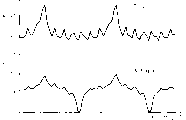
附图6为常规发电机和本发明发电机的转子场绕组电流波形图;Accompanying
附图7为本发明第二种实施方案的场绕组接线图;Accompanying
附图8为本发明第三种实施方案的场绕组接线图;Accompanying drawing 8 is the field winding wiring diagram of the third embodiment of the present invention;
附图9为本发明第四种实施方案的场绕组接线图。Accompanying
现在参考附图,讲述本发明无电刷三相同步发电机的几个优选实施方案。Referring now to the accompanying drawings, several preferred embodiments of the brushless three-phase synchronous generator of the present invention are described.
附图3、4、5和6展示了本发明无电刷三相同步发电机70的第一种实施方案。附图3为本发明发电机70的电路图。如附图3所示,本发明发电机70与附图1所示的常规发电机40其不同之处只在于转子侧60。附图4画出了总数为三套的转子场绕组其中的一套电路图。附图5为另外一种电路详图,它展示了三套转子绕组Wf51-Wf59的接线形式。附图6则画出了本发明发电机及常规发电机场绕组内的电流波形图。3, 4, 5 and 6 show the first embodiment of the brushless three-phase
本发明发电机70的定子侧41与常规发电机是一样的。具体地讲,定子41包括三相四极的一次发电绕组42,极数为12的定子激励绕组43,还有一个DC电源,定子激励绕组的极数为一次发电绕组42极数的奇数倍,DC电源带有若干个三相桥形连接二极管49和一个可变电阻48。另一方面,在转子侧60有若干个转子场绕组50,它们按正常节距集中地绕在一起,其绕组极数与一次发电绕组42的极数相同。在此实施例中,极数为4。在附图1所示的常规发电机40中,转子场绕组46分别由相应的二极管47(D1-D7)进行短接,而本发明发电机70的转子场绕组50其连接方式却如附图4所示。假设转子铁芯的槽数为36,且绕在上面的场绕组为4极,下面就来阐述转子的各个实施方案。在转子铁芯上,每极分配9个槽。在跨过四个极时,每一套场绕组均绕在12个槽上。一共有三套这样的场绕组绕在转子铁芯上。The
参考附图5,在圆柱形转子铁芯上绕有9个场绕组Wf51-Wf59(附图3中用数字50通用表示),它们按正常节距集中地绕在一起,由此而形成跨过半导体元件D11-D19的四个极。场绕组Wf51与Wf57作并联连接,而且它们在三次空间谐波磁场中感应的相电压是相同的,然后它们再并联在中心场绕组Wf54上,中心场绕组Wf54的作用为有效地产生一次场磁通。在整过详述中,词“中心场绕组”是指那些比其它场绕组产生更多一次场磁通的场绕组。类似地,场绕组Wf52与Wf58并联后再并联在中心场绕组Wf55上,而场绕组Wf53也是在与Wf59并联后再并联到中心场绕组Wf56上的。通常,半导体元件D11-D19为一些类似于二极管的整流器。Referring to accompanying drawing 5, there are 9 field windings Wf51 - Wf59 (commonly indicated by numeral 50 in accompanying drawing 3) wound on the cylindrical rotor core, and they are concentratedly wound together according to the normal pitch, thereby forming across the four poles of the semiconductor elements D11-D19. The field winding W f51 and W f57 are connected in parallel, and the phase voltage induced by them in the third space harmonic magnetic field is the same, and then they are connected in parallel on the center field winding W f54 , and the function of the center field winding W f54 is effectively Generate a field flux. Throughout the detailed description, the term "central field winding" refers to those field windings which generate more primary field flux than the other field windings. Similarly, the field winding Wf52 is connected in parallel with Wf58 and then connected in parallel with the center field winding Wf55 , and the field winding Wf53 is also connected in parallel with Wf59 and then connected in parallel with the center field winding Wf56 . Typically, the semiconductor elements D11-D19 are some diode-like rectifiers.
进一步讲,通过画出静磁场的空间基波、三次空间谐波成份以及五次空间谐波成份,或者说是电枢反应磁场的空间谐波成份,附图5展示了绕在转子槽S1-S36内场绕组Wf51-Wf59的位置关系。在三次空间谐波磁场中,场绕组Wf51与Wf57的感应电压相位是一样的,而在若干按正常节距集中排列的场绕组之间,Wf51与Wf57相互并联在一起,然后再与中心场绕组Wf54并联起来,且场绕组Wf54内的感应电压与上述电压是反相的。Furthermore, by drawing the space fundamental wave, the third space harmonic component and the fifth space harmonic component of the static magnetic field, or the space harmonic component of the armature reaction magnetic field, accompanying drawing 5 shows the The positional relationship of the field winding W f51 -W f59 in S36. In the third space harmonic magnetic field, the induced voltage phases of field windings W f51 and W f57 are the same, and between several field windings arranged in a normal pitch, W f51 and W f57 are connected in parallel with each other, and then It is connected in parallel with the central field winding W f54 , and the induced voltage in the field winding W f54 is in opposite phase to the above-mentioned voltage.
现在,阐述一下上述结构无电刷三相同步发电机70的工作过程。在转子60开始转动后,由于转子铁芯的剩磁作用,一次发电绕组42内将感应出一个电动势。该电动势产生交变电流(AC)流入一次发电绕组42,并流经DC电源44和定子激励绕组43。在这个AC电流基础上,一次发电绕组42的周围将产生电枢反应磁场。流入定子激励绕组43的DC电流在DC电源44的作用下产生一个静磁场,该磁场位于定子激励绕组43的周围。电枢反应磁场与静磁场形成重迭的磁场,于是在转子60的各个场绕组50内感应出电动势来,对于电枢反应磁场和静磁场,上述场绕组都会与它们的所有奇序空间高次谐波成份进行磁耦合。由此而在场绕组50内感应出的电动势将分别通过相应的二极管D11-D19进行半波整流,其获得的DC成份用来提高转子的场磁通。由于一次场磁通增加了,因此在定子一次发电绕组42内感应的电动势也会增加。通过这种方式,可以自建一个无载状态电压。至此,上述的工作过程同常规发电机是一样的。Now, the working process of the brushless three-
如附图4所示,在本发明发电机中,场绕组Wf51与Wf57通过各自相应的二极管D11与D17(DC转换电路)并联在一起,而且它们感应的电压相位是相同的。并联后的场绕组Wf51和Wf57再并接在中心场绕组Wf54上,而中心场绕组Wf54的作用为有效地产生一次场磁通。诸如二极管之类的环流器D14同中心场绕组Wf54相并联。As shown in Fig. 4, in the generator of the present invention, the field windings W f51 and W f57 are connected in parallel through respective corresponding diodes D11 and D17 (DC conversion circuit), and the voltage phases induced by them are the same. The parallel field windings W f51 and W f57 are then connected in parallel to the center field winding W f54 , and the function of the center field winding W f54 is to effectively generate a field flux. A circulator D14, such as a diode, is connected in parallel with the center field winding Wf54 .
流入场绕组Wf51与Wf57的电流分别由其相应的二极管D11、D17进行整流,由此得到的DC成份流入中心场绕组Wf54,从而有效地产生一次场磁通。由于上述DC成份及环流二极管D14的作用,就会有一个较大的DC成份流入中心场绕组Wf54,因此,一次场磁通将由于磁势的增加而相应增加。所以,如附图6所示,同常规发电机相比,流入中心场绕组Wf54内的电流大大增加了,而且场绕组内的电流波形也平滑了许多,其原因是由于DC成份增加了。因此,既然磁势增加了,发电机的效率也就可以有效地得到提高。The current flowing into the field windings Wf51 and Wf57 is rectified by their corresponding diodes D11, D17 respectively, and the resulting DC component flows into the center field winding Wf54 , effectively generating a primary field flux. Due to the above-mentioned DC component and the effect of the circulating diode D14, a large DC component will flow into the center field winding Wf54 , so the primary field flux will increase correspondingly due to the increase of the magnetic potential. Therefore, as shown in Fig. 6, compared with the conventional generator, the current flowing into the central field winding Wf54 is greatly increased, and the current waveform in the field winding is also much smoother due to the increased DC component. Therefore, since the magnetic potential is increased, the efficiency of the generator can be effectively increased.
继而,附图7展示了本发明场绕组的第二种实施方案。在本方案中,场绕组Wf51与Wf57内感应的相电压是一样的,首先,它们直接并联起来,以形成一个AC分量回路80,然后通过二极管D20与中心场绕组Wf54相并联。应该注意,在本实施方案中,相同相位的场绕组是在直接并联后再通过最后的共同二极管D20与中心场绕组并接起来。由于本发明带有这种AC分量回路,所以在发电机连接单相负载时,AC分量回路的场绕组之间就会流经一个环形电流,其原因在于,基于反向旋转磁场的上述场绕组其电流相位差为120度。因此,既然经过二极管D20流进中心场绕组Wf54的整流电流减小了,那么,由该绕组Wf54产生的场磁通也便相应有所降低,于是便防止了输出电压升至过高。另外,也防止了AC分量对场绕组的电流波形进行干扰,还可以防止自激现象所带来的过电压,而对于这种自激现象,它妨碍了场绕组起到阻尼线圈作用。Next, FIG. 7 shows a second embodiment of the field winding of the present invention. In this scheme, the phase voltages induced in the field windings Wf51 and Wf57 are the same. First, they are directly connected in parallel to form an AC component loop 80, and then connected in parallel with the central field winding Wf54 through the diode D20. It should be noted that in this embodiment, the field windings of the same phase are directly connected in parallel and then connected in parallel with the central field winding through the last common diode D20. Since the present invention has such an AC component circuit, when the generator is connected to a single-phase load, a circular current will flow between the field windings of the AC component circuit. The current phase difference is 120 degrees. Therefore, since the rectified current flowing into the center field winding Wf54 through the diode D20 is reduced, the field flux generated by this winding Wf54 is correspondingly reduced, thereby preventing the output voltage from rising too high. In addition, it also prevents the AC component from interfering with the current waveform of the field winding, and also prevents the overvoltage caused by the self-excitation phenomenon, which prevents the field winding from acting as a damping coil.
附图8展示了本发明场绕组电路的第三种实施方案。在本方案中,若干场绕组Wf51-Wf59按正常节距集中地绕在一起,其中,场绕组Wf52与Wf59内感应的电压相位是相同的,该相位与中心场绕组Wf54在奇序空间高次谐波磁场内感应的电压相位有一个预定的度差,场绕组Wf52与Wf59通过其相应的二极管D12、D19并联起来。然后,并联的场绕组Wf52与Wf59再并接到中心场绕组Wf54上,而场绕组Wf54又并联有一个环流二极管D14。Figure 8 shows a third embodiment of the field winding circuit of the present invention. In this scheme, a number of field windings W f51 -W f59 are wound together at a normal pitch, wherein the phases of the induced voltages in the field windings W f52 and W f59 are the same, and this phase is the same as that of the central field winding W f54 in The voltage phase induced in the odd-sequence space high-order harmonic magnetic field has a predetermined degree difference, and the field winding W f52 and W f59 are connected in parallel through their corresponding diodes D12 and D19. Then, the parallel field windings Wf52 and Wf59 are connected in parallel to the central field winding Wf54 , and the field winding Wf54 is connected in parallel with a circulating diode D14.
根据上述电路结构,流入中心场绕组Wf54的电流增加了,且其波形也平滑了许多,这同上述第一种实施方案是一样的。这里另外还有一些情况,就是发电机在实际中连接了负载时,要在中心场绕组Wf54电流与场绕组Wf52、Wf59的电流之间制造出一种相位差,在此,场绕组Wf52、Wf59均是同上述中心场绕组Wf54相并联的。尽管发电机在无载状态时存在相位差,但在实际中加上负载后,第三种实施方案就可利用上述考虑过的相位差将原来存在的相位差变至零。According to the above circuit structure, the current flowing into the center field winding Wf54 is increased and its waveform is much smoothed, as in the above-mentioned first embodiment. There are also some cases here, that is, when the generator is actually connected to a load, a phase difference must be created between the current of the central field winding W f54 and the currents of the field windings W f52 and W f59 , where the field winding Both Wf52 and Wf59 are connected in parallel with the center field winding Wf54 . Although there is a phase difference in the no-load state of the generator, after the load is applied in practice, the third embodiment can use the above considered phase difference to change the original phase difference to zero.
同第二种实施方案一样,第三种实施方案的无电刷三相同步发电机也可带有一个AC分量回路,它由场绕组Wf52与Wf59组成。发电机接上单相负载后,场绕组将由于与反相旋转磁场相交连而产生双倍频率的AC分量,该AC分量可由上述结构的回路进行吸收,这样就可防止AC分量对电流进行干扰作用,而且,由于转子场绕组起到了阻尼线圈作用,所以又防止了转子场绕组自激现象所带来的过电压。Like the second embodiment, the brushless three-phase synchronous generator of the third embodiment can also have an AC component circuit, which is composed of field windings Wf52 and Wf59 . After the generator is connected to a single-phase load, the field winding will generate an AC component of double frequency due to the cross-connection with the anti-phase rotating magnetic field. This AC component can be absorbed by the circuit of the above structure, thus preventing the AC component from interfering with the current. Moreover, since the rotor field winding acts as a damping coil, the overvoltage caused by the self-excitation phenomenon of the rotor field winding is prevented.
附图9展示了本发明的另一种实施方案,其中心场绕组Wf54分成两个次级中心场绕组Wf54a和Wf54b,一个接在场绕组Wf51上,而另一个则接在场绕组Wf57上。如果希望在槽S1(其中带有场绕组Wf51)与槽S7(其中带有场绕组Wf57)之间产生干涉的话,本实施方案将非常有利。Accompanying drawing 9 has shown another embodiment of the present invention, and its central field winding Wf54 is divided into two secondary central field windings Wf54a and Wf54b , one is connected on the field winding Wf51 , and the other is then connected to the field winding W on f57 . This embodiment is very advantageous if it is desired to create interference between slot S1 (with field winding Wf51 in it) and slot S7 (with field winding Wf57 in it).
如上文所述,对于本发明的同步发电机,流入场绕组的电流原本是不能有效地产生场磁通的,但是,在它们经过二极管半波整流后,由此获得的DC成份可集中流到中心场绕组中去,于是就可有效地产生一次场磁通了,这样,流入中心场绕组的DC成份增加了,且电流波形也平滑了许多。由于电流平滑了许多,所以场磁势变得很大,且激励效率也得到了增加,由此大大提高了发电机的效率。As mentioned above, for the synchronous generator of the present invention, the current flowing into the field winding cannot effectively generate the field flux originally, but after they are rectified by the diode half-wave, the DC components thus obtained can flow concentratedly to the In this way, the DC component flowing into the center field winding is increased, and the current waveform is much smoother. Since the current is much smoother, the field potential becomes larger and the excitation efficiency is increased, thereby greatly improving the efficiency of the generator.
当发电机在实际中接上负载时,在中心场绕组电流相位和其它场绕组电流相位之间可能产生一个相位差,从理论上讲,其它场绕组内流经的电流相位是一样的。尽管在无载状态下存在一个相位差,但由于考虑了上述相位差,所以在负载状态时可以使相位达到相同。When the generator is actually connected to the load, there may be a phase difference between the central field winding current phase and the other field winding current phases. In theory, the current phases flowing in the other field windings are the same. Although there is a phase difference in the no-load state, the phase can be made the same in the load state by taking the above-mentioned phase difference into consideration.
通过提供一种由最后两个场绕组直接并联的电流回路,在发电机连接单相负载时,用它来吸收反向旋转磁场交联所产生的双倍频率AC分量,这样就可有效地防止AC分量带来的电流波形干扰,而且,由于转子场绕组起到了阻尼线圈作用,所以也防止了自激现象产生过电压。By providing a current loop directly paralleled by the last two field windings, when the generator is connected to a single-phase load, it is used to absorb the double frequency AC component generated by the cross-linking of the reverse rotating magnetic field, which can effectively prevent The current waveform interference brought by the AC component, and because the rotor field winding acts as a damping coil, it also prevents the self-excitation phenomenon from generating overvoltage.
应当理解,在讲述本发明优选实施方案时,只是采用了描述性的词语,而不是限制性词语,而且,在从属权利要求范围内可以作一些变化,但不会脱离本发明在权利要求中定义的真正范围。It is to be understood that, while describing the preferred embodiment of the invention, words of description rather than limitation have been used, and that changes may be made within the scope of the appended claims without departing from the invention as defined in the claims. true range.
Claims (4)
Applications Claiming Priority (6)
| Application Number | Priority Date | Filing Date | Title |
|---|---|---|---|
| JP34422697 | 1997-11-28 | ||
| JP344226/97 | 1997-11-28 | ||
| JP344226/1997 | 1997-11-28 | ||
| JP12797798A JP3788494B2 (en) | 1997-11-28 | 1998-05-11 | Brushless three-phase synchronous generator |
| JP127977/1998 | 1998-05-11 | ||
| JP127977/98 | 1998-05-11 |
Publications (2)
| Publication Number | Publication Date |
|---|---|
| CN1222781A CN1222781A (en) | 1999-07-14 |
| CN1118921C true CN1118921C (en) | 2003-08-20 |
Family
ID=26463783
Family Applications (1)
| Application Number | Title | Priority Date | Filing Date |
|---|---|---|---|
| CN98122944A Expired - Fee Related CN1118921C (en) | 1997-11-28 | 1998-11-27 | Brushless three-phase synchronous generator having enhanced rotor field system |
Country Status (5)
| Country | Link |
|---|---|
| US (1) | US6130492A (en) |
| EP (1) | EP0920112B1 (en) |
| JP (1) | JP3788494B2 (en) |
| CN (1) | CN1118921C (en) |
| DE (1) | DE69803353T2 (en) |
Families Citing this family (12)
| Publication number | Priority date | Publication date | Assignee | Title |
|---|---|---|---|---|
| CN100454726C (en) * | 2001-11-27 | 2009-01-21 | 泰豪科技股份有限公司 | Great-capacity single-phase brush-less synchronous generator |
| JP2006174692A (en) * | 2004-11-19 | 2006-06-29 | Nippon Densan Corp | Brushless motor |
| JP5302527B2 (en) | 2007-10-29 | 2013-10-02 | 株式会社豊田中央研究所 | Rotating electric machine and drive control device thereof |
| JP2009112169A (en) * | 2007-10-31 | 2009-05-21 | Honda Motor Co Ltd | Generator output control device |
| FR2949176B1 (en) * | 2009-08-14 | 2011-09-16 | Leroy Somer Moteurs | ROTATING ELECTRIC MACHINE COMPRISING AN EXCITATOR |
| US8008827B1 (en) * | 2010-02-18 | 2011-08-30 | Tesla Motors, Inc. | Triple layer winding pattern and methods of manufacturing same |
| DE102010041068A1 (en) * | 2010-09-20 | 2012-03-22 | Robert Bosch Gmbh | System for charging an energy storage and method for operating the charging system |
| DE102010041034A1 (en) | 2010-09-20 | 2012-03-22 | Robert Bosch Gmbh | Method for transferring energy between at least two energy storage cells in a controllable energy store |
| US10075051B2 (en) * | 2015-03-16 | 2018-09-11 | Foster-Miller, Inc. | Series-wound heteropolar inductor motor |
| CN105207555B (en) * | 2015-09-18 | 2018-03-09 | 重庆铭贝科技有限公司 | A kind of Digital-typed Generator automatic regulating system and its method |
| CN110401387A (en) * | 2019-08-13 | 2019-11-01 | 福建凯威斯发电机有限公司 | A kind of bifrequency switching generator |
| JP7673049B2 (en) | 2020-03-24 | 2025-05-08 | ソニーセミコンダクタソリューションズ株式会社 | Light receiving device and distance measuring device |
Family Cites Families (5)
| Publication number | Priority date | Publication date | Assignee | Title |
|---|---|---|---|---|
| JPS583554A (en) * | 1981-06-26 | 1983-01-10 | Fukuo Shibata | Brushless synchronous machine structure |
| DE3669816D1 (en) * | 1985-07-04 | 1990-04-26 | Bbc Brown Boveri & Cie | AC MOTOR FOR SYNCHRONOUS MACHINES. |
| US4851758A (en) * | 1987-03-09 | 1989-07-25 | Sawafuji Electric Co., Ltd. | Brushless generator |
| JPH0787717A (en) * | 1993-09-18 | 1995-03-31 | Satake Eng Co Ltd | Brushless synchronous generator |
| JP3489105B2 (en) * | 1994-08-11 | 2004-01-19 | 株式会社サタケ | Brushless self-excited three-phase synchronous generator |
-
1998
- 1998-05-11 JP JP12797798A patent/JP3788494B2/en not_active Expired - Fee Related
- 1998-08-10 DE DE69803353T patent/DE69803353T2/en not_active Expired - Fee Related
- 1998-08-10 EP EP98306373A patent/EP0920112B1/en not_active Expired - Lifetime
- 1998-09-16 US US09/154,091 patent/US6130492A/en not_active Expired - Fee Related
- 1998-11-27 CN CN98122944A patent/CN1118921C/en not_active Expired - Fee Related
Also Published As
| Publication number | Publication date |
|---|---|
| DE69803353T2 (en) | 2002-09-19 |
| DE69803353D1 (en) | 2002-02-28 |
| CN1222781A (en) | 1999-07-14 |
| EP0920112A1 (en) | 1999-06-02 |
| JP3788494B2 (en) | 2006-06-21 |
| EP0920112B1 (en) | 2002-01-02 |
| US6130492A (en) | 2000-10-10 |
| JPH11220857A (en) | 1999-08-10 |
Similar Documents
| Publication | Publication Date | Title |
|---|---|---|
| CA1164933A (en) | Variable speed electric machine having controlled magnetic flux density | |
| US5694027A (en) | Three-phase brushless self-excited synchronous generator with no rotor excitation windings | |
| US6570289B1 (en) | Low noise automotive alternator | |
| US11515771B2 (en) | Alternating-current driven, salient-teeth reluctance motor with concentrated windings | |
| US20240006967A1 (en) | Field winding type rotating electric machine | |
| CN1118921C (en) | Brushless three-phase synchronous generator having enhanced rotor field system | |
| CN111987832B (en) | Exciting coil type rotary electric machine | |
| US5598091A (en) | Three-phase brushless self-excited synchronous generator with no rotor exciting windings | |
| JP7095532B2 (en) | Field winding type rotary electric machine | |
| CN112753156B (en) | Field winding type rotating electrical machine | |
| CN111712999A (en) | Field winding type rotating electrical machine | |
| US4786853A (en) | Brushless capacitor excited generator | |
| JPH11220857A5 (en) | ||
| JP2939914B2 (en) | Brushless self-excited synchronous generator | |
| US20030080643A1 (en) | Brushless rotating electric machine | |
| CN1042631A (en) | Have the potential source excitation system that voltage and current is regulated | |
| JPH03245755A (en) | Brushless self-excitation synchronous electric motor | |
| JP3539148B2 (en) | Cylindrical synchronous generator | |
| JPH077999A (en) | AC generator | |
| JP3489108B2 (en) | Brushless self-excited single-phase synchronous generator | |
| SU1234925A1 (en) | Contactless generator | |
| Chakraborty et al. | Performance of a Doubly Excited Cylindrical Rotor Brushless Synchronous Generator | |
| JPH06269151A (en) | Brushless synchronous generator | |
| SU1117794A1 (en) | Static frequency converter | |
| JPH0724930Y2 (en) | Brushless single phase alternator |
Legal Events
| Date | Code | Title | Description |
|---|---|---|---|
| C06 | Publication | ||
| PB01 | Publication | ||
| C10 | Entry into substantive examination | ||
| SE01 | Entry into force of request for substantive examination | ||
| C14 | Grant of patent or utility model | ||
| GR01 | Patent grant | ||
| C19 | Lapse of patent right due to non-payment of the annual fee | ||
| CF01 | Termination of patent right due to non-payment of annual fee |